EP1345818B1 - Vent comprising air permeable liner - Google Patents
Vent comprising air permeable liner Download PDFInfo
- Publication number
- EP1345818B1 EP1345818B1 EP01988090A EP01988090A EP1345818B1 EP 1345818 B1 EP1345818 B1 EP 1345818B1 EP 01988090 A EP01988090 A EP 01988090A EP 01988090 A EP01988090 A EP 01988090A EP 1345818 B1 EP1345818 B1 EP 1345818B1
- Authority
- EP
- European Patent Office
- Prior art keywords
- vent
- wall
- container
- liner
- face
- Prior art date
- Legal status (The legal status is an assumption and is not a legal conclusion. Google has not performed a legal analysis and makes no representation as to the accuracy of the status listed.)
- Expired - Lifetime
Links
Images


Classifications
-
- B—PERFORMING OPERATIONS; TRANSPORTING
- B65—CONVEYING; PACKING; STORING; HANDLING THIN OR FILAMENTARY MATERIAL
- B65D—CONTAINERS FOR STORAGE OR TRANSPORT OF ARTICLES OR MATERIALS, e.g. BAGS, BARRELS, BOTTLES, BOXES, CANS, CARTONS, CRATES, DRUMS, JARS, TANKS, HOPPERS, FORWARDING CONTAINERS; ACCESSORIES, CLOSURES, OR FITTINGS THEREFOR; PACKAGING ELEMENTS; PACKAGES
- B65D51/00—Closures not otherwise provided for
- B65D51/16—Closures not otherwise provided for with means for venting air or gas
- B65D51/1605—Closures not otherwise provided for with means for venting air or gas whereby the interior of the container is maintained in permanent gaseous communication with the exterior
- B65D51/1616—Closures not otherwise provided for with means for venting air or gas whereby the interior of the container is maintained in permanent gaseous communication with the exterior by means of a filter
Definitions
- the package of Gerhart et al., WO 0 104 006 A (Serial No. 09/350,476) was available to various members of the public without confidentiality restrictions. That package was a 300 oz. Container which includes one or more top walls having a vent opening and closure, a handle, a spigot for releasing product, and a measuring cap which serves as a closure for the spigot.
- venting of the container requires partial unscrewing of the vent cap, and in the event that the bottle is transported or otherwise moved while the vent cap is not securely fastened, the possibility of product inadvertently escaping from the package exists.
- U.S. Patent No. 3,951,293 discloses a gas permeable liquid closure for containers of liquids or solids which emit or absorb gas.
- the closure includes a gas permeable film of unsintered tetrafluoroethylene.
- the film is supported across an opening of the container by a perforated cap or perforated sealing diaphragm.
- the vent stopper of the '293 patent is said to be suitable for containers of all kinds.
- the gas permeable material is an unsintered tetrafluoroethylene polymer with a fibrillated structure and a density of less than about 1.4.
- Fig. 3 the disk of unsintered tetrafluoroethylene polymer with a fibrillated structure and a density of less than about 1.4 is held only by ring-shaped ridges and practically the entire surface of the disk is available for the passage of gas without coming in contact in the center with the cover bottom or the lockable core.
- Baginski et al. U.S. Patent No. 5,882,454 discloses a venting cap with a hole and a semi-permeable membrane.
- the membrane is fitted in a housing of particular dimensions which is in turn fitted in a protrusion corresponding to the hole in the caps.
- the membrane is understood to be sufficiently permeable to gases which may be generated inside the container in order to allow the gases to escape to the ambient and sufficiently impermeable to the substance contained in the container in order to prevent significant leakage, preferably all of leakage.
- Suitable materials are said to include polyethylene, high and low density, polypropylene, nylon and PTFE.
- Preferred materials are polyethylene film sold under the trademark Tyvek and an acrylic copolymer cast on a non-woven support with a fluoro monomer post treatment sold under the trademark Versapor.
- the housing and the protrusion may be simply glued together, spin welded or interference fitted together.
- the cap may have a top wall and a depending skirt.
- U.S. Patent No. 4,863,051 discloses a lid for a container for gas releasing liquids which includes a sealing cap having an opening closed by means of a foil of gas permeable, but liquid non-permeable material.
- U.S. Patent No. 5,988,414 discloses a lid having a pressure compensation device comprising a gas permeable, liquid impermeable membrane.
- the membrane is integrated in an upper cover portion of the lid by injection molding.
- U.S. Patent No. 5,730,306 is directed to a dual cap lining or bi-directional venting which includes a disk shaped gas permeable material bottom layer and a polyethylene material top layer which is provided with apertures which communicate with the bottom layer.
- Costa et al., U.S. Patent No. 5,579,936 is directed to a dual cap lining for bi-directional venting comprising a gas permeable material bottom layer having an extruded polyethylene material top layer which is provided with channels.
- the material of the bottom layer is gas permeable such that the dual lining allows bi-directional gas flow therethrough for gases which have built up in the interior of the container, and reverse venting to equilibrate for relatively increased external pressure.
- Baginski et al. US Patent No. 5,882,454 mentions in column 1 that it is customary to design membranes which are force fitted into a cap having a venting hole.
- US Patent No. 4,765,499 which is described as proposing an arrangement wherein a small membrane is fit into a liner, the size of which corresponds to the inside diameter of the cap.
- AU 9341259 said to be directed to a venting cap wherein a small membrane is secured to the inner surface of the cap's top wall by ultrasonic welding.
- the application is also directed to a venting closure according to claim 8.
- venting closure is used in conjunction with a large volume heavy duty liquid detergent container according to claim 12.
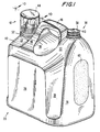
- Container or bottle 20 includes top wall 22, front wall 24, side walls 26, 28, 30, 32, 34 and 35, and rear wall 36.
- Bottom wall 38 supports the container.
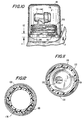
- Top wall 22 includes a recessed area 40 in which is disposed valve or spigot apparatus 42 and closure/measuring cup 44, which will be described in greater detail below.
- handle 46 Medially disposed with respect to valve or spigot assembly 42 is handle 46 which is integral with top wall 22.
- Handle 46 includes a base 48 having an interior aspect 50 and an exterior aspect 52.
- the interior of handle 46 is generally oval shaped as can be seen e.g., in Fig. 2.
- vent 56 and vent cap 58 Disposed laterally to handle 46 and on an opposite side from spigot assembly 42 is vent 56 and vent cap 58 with vent opening 300 in its top wall.
- the height of the highest point of wall 22 adjacent vent 56 is considerably higher than that in recessed area 40.
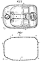
- Rear wall 36 includes oval etched area 60. The etching provides a non-uniform or rough surface for reasons which will be discussed below.
- the recessed area 40 in which the spigot assembly 42 is disposed is isolated from the interior aspect 50 of handle 46 by handle base 48. It is anticipated that isolation of the spigot area from the interior of the handle will prevent itinerant liquid product from migrating from the spigot area to the interior of the handle.
- the top surfaces of measuring cup 44, handle 46, and vent cap 58 are generally parallel. Moreover, the heights of the top surfaces of the measuring cup 44 and the vent cap 58 are independently within one inch of the top surface of handle 46, especially within 3 ⁇ 4 of an inch of the top surface of handle 46, and most preferably within 1 ⁇ 2 inch of the top surface of the handle 46. Keeping the top surfaces parallel and at approximately the same height facilitates the even distribution of top load of containers in that the effective top surface of the container seen by a container stacked on top of it will be more or less even whereby to prevent uneven stacking of the containers.
- the handle and top wall of the container body include several features which it is believed contribute to an improved compressive strength.
- the forward and rear walls 210, 212 of the handle are generally curved rather than having rectilinear sides which meet at relatively sharp angles with each other or with the top wall 22.
- the width of the base at the handle's front end is at least twice the width of the handle, preferably at least three times, still more preferably at least four or five times the width of the handle (also measured along a horizontal axis).
- the rear end of the handle merges curvedly with the elevated top wall 22 adjacent to the vent cap so that, again, any force transmitted from the handle is dissipated over a large area rather than concentrated at a few points.
- the preferred package includes eight vertically extending side panels, including the front and rear walls.
- Use of six or more, especially use of eight or more side walls or panels is believed to enhance the compression strength of the container and to permit the use of less resource, e.g. thermoplastic polymers, in its manufacture.
- Use of less resource in manufacture in turn leads to less waste material after the useful life of the container is complete.
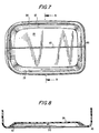
- bottom wall 38 includes outer rim 80 which comprises the primary support for the container. Heel 80 extends downwardly further than other aspects of the bottom wall 38.
- Wall 38 may include the base push-up construction shown in the Fig. 7 wherein an angled portion 82 is disposed inwardly of first ring 80 and medial aspect 84 of wall 38 is disposed further inwardly.
- Parting line 86 (Fig. 7) is an artifact of container manufacture when the container is blow molded. Parting line 86 reflects the joining of two halves of the mold used to make the container. It may be desirable, as illustrated in Figs. 7 and 8, to have a rib 90 of enhanced thickness and length at the parting line to provide support when the weight of the liquid product pushes downwardly on the medial aspect 84 of bottom wall 38. In such circumstances, rib 90 will assist in supporting the weight of the product.
- the structural support rib along the middle of the push-up is known per se and is also called the "pinch-off." As the push-up inverts due to the weight of the liquid contents, the rib may contact the flat surface and prevent further inversion of the push-up.
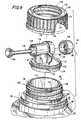
- top wall 22 has disposed therein annular dispensing opening 90.
- Dispensing opening 90 is supported by base 92 and by finish 94.
- Base 92 is generally circular and may include a plurality of levels as is illustrated in Fig. 9. In at least one level, elongated tabs 96 which are equally spaced from each other along the circumference of the base, serve to mate with a bead on the measuring cup, as will be described below. Below tab 96 a step 98 is provided in base 92 to support the measuring cup 44 when it is in place over the spigot assembly.
- finish 94 At the bottom of finish 94 are disposed two oppositely positioned sets of ratchets 100. Finish 94 is also provided with external threads 102 for mating with internal threads 104 on valve securement collar 106. Top thread 108 includes mirror image wedges 110, 112 which serve to facilitate alignment of valve base 114 when the spigot is in place by providing lug confining walls.
- Valve base 114 includes spigot or valve 116, valve support column 118, spigot support platform 120, outer ring 122 and inner depending ring 124.
- Spigot support 114 is placed within dispensing aperture 90 by snap fitting inner ring 124 within the mouth of aperture 90.
- Outer ring 122 includes one or more oppositely disposed depending lugs 130, which are accommodated in a space between each of the mirror image wedges 110, 112. This facilitates the proper alignment of spigot supporting structure 114 and ultimately of spigot 116.
- Spigot 116 includes a valve mechanism of a type available from the David S. Smith Worldwide Dispensers of Merton, London of Great Britain.
- the spigot comprises spigot housing 134 resilient actuating button 136, valve stem 138, valve stem gripper 148 and valve 140. Operation of this simple valve is best seen with reference to Figs. 14 and 16.
- the consumer rests the container on front wall 24 by pivoting the container forward along the front section of ring 80 of bottom wall 38.
- the consumer dispenses product by pressing the resilient actuator button 136, which receives valve stem 138 in circular retaining structure, gripper 148.
- gripper 148 is also resilient and slightly narrower than the diameter of the valve stem 148.
- the force applied by the consumer's finger is transmitted through valve stem 138 and forces valve 140 away from valve seat 150. This permits product to flow through the spigot and into the wash, or more preferably, into measuring cup 44.
- Gripping wings 160, 162 are disposed on either side of valve housing 134 to permit the consumer to grasp the valve housing with two fingers while applying pressure with the thumb.
- the spigot assembly 116 is secured to bottle finish 94 by spigot or valve collar 106.
- Internal threads 104 mate with external threads 102 on the bottle finish. Opening 170 on the spigot collar permits the spigot to extend outside of the collar.
- the top of the spigot collar includes flange 172 which rests upon outer ring 122 of the spigot base when the collar is secured in place on the spigot finish.
- lugs 178 which mate with ratchet 100 at the bottom of the spigot finish to secure more or less permanently the collar to the container.
- spigot collar 106 may be provided with vertically extending ribs 180 to assist in rotating the collar when it is applied to the container.
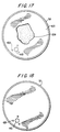
- vent 56 comprises vent finish 166 (Fig. 15) which may be threaded with external thread 168 to mate with internal thread 170 on vent cap 58.
- vent cap could be spin welded, sonically welded or adhered with hot melt or other adhesives, in which cases the threads may be omitted.
- vent hole 410 permits air to flow inwardly, through Gore-Tex fabric layer 420 as illustrated by the arrows in Fig. 15, and thereby to replace with air the volume of product lost when product is dispensed through spigot 116.
- Gore-Tex (trademark), is available from W.L. Gore & Co.
- Liner 420 permits passage of air and other gases but not liquids such as the heavy duty liquid detergent contained within the package. Other materials may be used so long as they permit inward flow of air and prevent flow of liquids into or out of the container.
- the vent opening finish is externally threaded and its external threads mate with internal threads on the vent closure.
- the vent closure may be a push/pull closure, disc-top or snap-top closure.
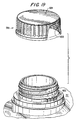
- Liner 420 may be made of polytetrafluoroethylene or any other suitable lining material which permits passage of air but does not permit passage of liquids through the vent hole. As best seen in Figs. 15 and 17, liner 420 is adhered to the surface of the bottom face 424 of top vent closure wall 426. Protuberances 428 extend downwardly from the inner or lower face of wall 426 in the vicinity of vent opening 410, thereby spacing liner 420 from wall 426 in the area of vent hole 410. Spacing of liner 420 from vent hole 410 has been found to be of importance in facilitating the intake of air during venting of the container. As an alternative, liner 420 can be friction fit within the confines of depending circular wall 434 of vent cap 58.
- ratchets may be employed to prevent removal of cap 58 by consumers once it has been secured to vent finish 166, so as to avoid the possibility of leakage in the event that the cap is opened.
- Fig. 19 shows a vent cap 58a having vent 604 and lugs 600 and vent finish with ratchets 602 which mate with the lugs.
- the vent cap is preferably secured to the container sealingly and permanently so that it can not be loosened by consumers to permit escape of liquid product.
- Examples of other materials which are suitable for layer 420 are nylon, polypropylene, polyester and high and low density polyethylene.
- spacers may be utilized in appropriate circumstances, such as a spacing ring.
- the spacer is present at least at three spaced points along the periphery of the vent opening so as to keep liner 420 spaced from the entire vent hole, if possible.
- Vent hole 410 and the protuberances and adhesive are seen in phantom in Fig 17 underneath liner 420.
- liner 420 has been removed to illustrate the vent hole and protuberances more clearly.
- the container when the container is in its dispensing position resting on front wall 24, it may be desirable to rest momentarily measuring cup 44.
- the container may be made of a material, such as certain thermoplastics, which is relatively smooth, in accordance with the invention, a non uniform section may be provided within one of the walls to assist in maintaining the cup in its position while it is disposed on the container.
- An example is illustrated in Fig. 14 wherein surface 60 which has a racetrack-like periphery, has been etched into rear wall 36. This is expected to minimize any tendency of measuring cup 44 to slip or slide on the surface of the container.
- Front panel 24 includes a large flat area to provide a stable base and to resist rocking during the dispensing operation. The side of the bottle adjacent the top vent closure becomes the top of the bottle in the dispensing position.
- This panel 36 is flat and level and has the textured surface wherein the measuring cup can be placed between uses in the upright position.
- Measuring cup 44 serves the dual function of measuring cup and closure for the spigot assembly.
- Measuring cup 44 is releasably secured to the container in its inverted position by being snap fit over equi-spaced ribs or lugs 96, which mate with bead 190 at the mouth of the cup.
- the measuring cup can be secured to the bottle base finish by use of a continuous thread to screw on the bottle base finish or by other means.
- cup's annular bead and the bottle's three or more lugs are designed to stay engaged during the impact of case packing as well to as withstand the rigors of shipping and warehousing without becoming dislodged.
- the container may be mono-layer or multi-layer and may be made of HDPE, PP, PVC, PET, POLYCARBONATE or acrylic or nitrite base resins, and preferably contains a minimum of 25% PCR.
- the measuring cup has textured fill line bands etched into the interior of the cup to aid the consumer visually in filling to the proper dose.
- the measuring cup may have a v-groove channel on the exterior of the mouth, similar to a laboratory beaker, to aid in pretreating strains with precise pouring. This channel could have an anti-drip lip. Alternatively, there may be "V" or "U” notches in the top side wall for a controlled pour.
- the measuring cup can include a handle.
- the measuring cup could have an exterior, annular anti-drip lip.
- the container or bottle of the inventions may be pigmented opaque or may be made clear by fabricating it from clarified grades of the aforementioned resins.
- the bottle, valve, valve collar and vent closure may be made of anti-static grades of the aforementioned resins.
- the tap collar and vent closure are preferably made of a polyolefin resin, most preferably PP.
- the pigmented tap body is the same color as the pigmented tap collar and vent closure. Alternatively, these components may be clear and the measuring cup could be opaque.
- the front and back panels of the bottle include in-mold labels (IML labels), preferably plastic IML's.
- IML labels may be opaque or clear.
- Polypropylene (PP) IMLs may be used to reduce blistering given that the containers of the invention may have a relatively large label area.
- IML in-mold labels
- PP Polypropylene
- the bottles front/back panels may be waffled.
- vent closure and the second bottle neck finish are in the same horizontal place as said first neck finish.
- the measuring cup may be attached to lugs at the base of the second neck finish and positioned over the vent closure.
- the base of the bottle could be larger in length and thickness than the label panel's greatest length and thickness, so that labels would not contact the walls of the corrugated shipping container or the label of another bottle.
Landscapes
- Engineering & Computer Science (AREA)
- Mechanical Engineering (AREA)
- Closures For Containers (AREA)
Description
Disposed laterally to handle 46 and on an opposite side from
Claims (17)
- A vent comprising:(a) a wall (426),(b) a venting opening (410) in said wall,(c) said wall having a first face and a second face,(d) one or more spacers (428) on said first wall face,(e) said first face (424) having a surface,(f) a liner (420) spaced from said venting opening (410) by said spacers,(g) said liner (420) being of a material which permits air to pass through the vent hole, characterised in that the liner (420) is adhered to a portion of the surface of said first face of the wall.
- A vent according to claim 1 wherein said liner (420) is of a material which does not permit liquids to pass through said vent hole.
- A vent according to claim 1 or claim 2 wherein said liner (420) is of a material which does not permit liquid detergents to pass through said vent hole (420).
- A vent according to any preceding claim wherein said liner (420) is comprised of tetrafluoroethylene polymer.
- A vent according to any preceding claim wherein said liner (420) is comprised of unsintered, fibrillated tetrafluoroethylene polymer.
- A vent according to any preceding claim wherein vent is a vent cap (58) and said wall (426) further comprises a depending cylindrical side wall (434) adjacent said first face (424) and having fasteners for fastening to a container.
- A vent according to any preceding claim wherein said one or more spacers are comprised of protuberances (428).
- A vent according to claim 1, in the form of a venting closure (58)(a) wherein said wall is a top wall,(b) a venting opening comprised in said top wall,(c) said top wall (426) has an outer face and an inner face (424) having a surface,(d) at least two said spacers (428) being present on said wall inner face, and further comprising,(e) a depending cylindrical side wall (434) adjacent said first face,(f) said liner being adjacent said inner face (424) and spaced from said venting opening by said spacers (428), said liner (420) being adhered to a portion of said inner face surface.
- A closure (58) according to claim 8 wherein said spacers are comprised of protuberances (428).
- A according to claim 8 or claim 9 wherein said liner (420) is of a material which does not permit liquids to pass through said vent hole.
- The closure according to any of claims 8-10 wherein said liner (420) is comprised of polytetrafluoroethylene.
- A container (20) comprising a top wall, a side wall, a bottom wall (38), a container venting opening in at least one of said top and side walls, a vent according to claim 1, said vent being a venting closure adapted to close said venting opening, said vent (58) wall an comprising a top closure wall, said venting opening being in said top closure. wall, said top closure wall having an outer face and an inner face (424) comprising said first face, said one or more spacers (428 being) on said wall inner face, and a depending cylindrical side wall adjacent said inner face, said liner (420) adjacent said inner face and spaced from said venting opening by said spacers, said liner (420) being partly adhered to said inner face surface.
- A container (20) according to claim 12 wherein said spacers are comprised of a plurality of protuberances (420).
- A container (20) according to claim 12 or claim 13 wherein said liner (420) is of a material which does not permit liquids to pass through said vent hole.
- A container (20) according to any of claims 12-14 further comprising a further opening (90) suitable for dispensing product from the container.
- A container (20) according to any of claims 12-15 wherein said container further comprises a spigot (116) for releasing product from said product dispensing opening and said container.
- A container (20) according to claim 16 wherein said container includes one or more upper walls and said one or more upper walls comprise said spigot (116), said product dispensing opening, and a handle (46).
Applications Claiming Priority (3)
| Application Number | Priority Date | Filing Date | Title |
|---|---|---|---|
| US749957 | 2000-12-28 | ||
| US09/749,957 US6523724B2 (en) | 2000-12-28 | 2000-12-28 | Container |
| PCT/EP2001/015404 WO2002053470A2 (en) | 2000-12-28 | 2001-12-18 | Vent comprising air permeable liner |
Publications (2)
| Publication Number | Publication Date |
|---|---|
| EP1345818A2 EP1345818A2 (en) | 2003-09-24 |
| EP1345818B1 true EP1345818B1 (en) | 2005-03-16 |
Family
ID=25015925
Family Applications (1)
| Application Number | Title | Priority Date | Filing Date |
|---|---|---|---|
| EP01988090A Expired - Lifetime EP1345818B1 (en) | 2000-12-28 | 2001-12-18 | Vent comprising air permeable liner |
Country Status (10)
| Country | Link |
|---|---|
| US (1) | US6523724B2 (en) |
| EP (1) | EP1345818B1 (en) |
| AR (1) | AR034285A1 (en) |
| AT (1) | ATE290985T1 (en) |
| AU (1) | AU2002240888A1 (en) |
| BR (1) | BR0116588A (en) |
| CA (1) | CA2430805C (en) |
| DE (1) | DE60109488T2 (en) |
| ES (1) | ES2236339T3 (en) |
| WO (1) | WO2002053470A2 (en) |
Families Citing this family (19)
| Publication number | Priority date | Publication date | Assignee | Title |
|---|---|---|---|---|
| US20040173556A1 (en) * | 1997-09-19 | 2004-09-09 | Smolko Daniel D. | Vented closures for containers |
| US7357266B2 (en) * | 2003-12-30 | 2008-04-15 | Unilever Home & Personal Care Usa, Division Of Conopco, Inc. | Venting closure |
| US7357709B2 (en) * | 2004-04-12 | 2008-04-15 | Gore Enterprise Holdings | Metal vent |
| US7950908B2 (en) | 2005-01-26 | 2011-05-31 | Seiko Epson Corporation | Fluid transporting device of a peristalic type with tube and push pin arrangement |
| US20070006925A1 (en) * | 2005-07-06 | 2007-01-11 | Toscano Jennifer E | Washer fluid reservoir having a fluid-impermeable air vent patch |
| WO2007009076A2 (en) * | 2005-07-12 | 2007-01-18 | Nottingham Spirk Design Associates, Inc. | Polymeric cereal container as well as system and method utilizing same |
| WO2007103580A2 (en) * | 2006-03-09 | 2007-09-13 | Conair Corporation | Steam cleaner with liquid dispenser |
| US7644734B2 (en) * | 2007-03-15 | 2010-01-12 | Safety Pumping Systems, Llc | Safety cap for couplings and fittings |
| US20090263892A1 (en) * | 2008-04-18 | 2009-10-22 | Henry Joseph Cattadoris | Float valve for cell culture vessel |
| US8177082B2 (en) * | 2008-04-18 | 2012-05-15 | Corning Incorporated | Flexible membrane valve for cell culture vessel |
| GB0821083D0 (en) * | 2008-11-19 | 2008-12-24 | Reckitt Benckiser Nv | Product |
| US20100175850A1 (en) * | 2009-01-09 | 2010-07-15 | Kaucic Edward M | Relief Vent for a Hot Fill Fluid Container |
| NL2003676C2 (en) * | 2009-10-20 | 2011-04-21 | Sara Lee De Nv | Fluid packaging container. |
| US20130105520A1 (en) * | 2011-11-02 | 2013-05-02 | Thomas Barber | Batter dispenser and method for using same |
| US9919850B2 (en) * | 2013-02-12 | 2018-03-20 | Ecolab Usa Inc. | Vented fitment for flexible pouch |
| USD842113S1 (en) * | 2017-09-21 | 2019-03-05 | Henkel IP & Holding GmbH | Tapped detergent bottle |
| USD851491S1 (en) * | 2017-11-13 | 2019-06-18 | Henkel Ag & Co. Kgaa | Dual handle container |
| USD850270S1 (en) * | 2017-11-30 | 2019-06-04 | The Procter & Gamble Company | Bottle |
| JP7198983B2 (en) * | 2020-04-21 | 2023-01-05 | パナソニックIpマネジメント株式会社 | Bottle |
Family Cites Families (20)
| Publication number | Priority date | Publication date | Assignee | Title |
|---|---|---|---|---|
| FR1357064A (en) | 1963-02-20 | 1964-04-03 | Gas permeable cap | |
| US3521784A (en) | 1968-11-29 | 1970-07-28 | Du Pont | Closure-cap having venting gasket |
| DE2403244C3 (en) | 1974-01-24 | 1980-12-04 | Riedel-De Haen Ag, 3016 Seelze | For gases permeable, liquid-tight shut-off device |
| US4811870A (en) * | 1984-03-29 | 1989-03-14 | The Dyson-Kissner-Moran Corporation | Liquid container with rotatable spout |
| DE3627990A1 (en) | 1986-08-18 | 1988-02-25 | Schering Ag | LOCK FOR LIQUID CONTAINERS |
| US4765499A (en) | 1987-12-29 | 1988-08-23 | Von Reis Charles | Filter cap |
| US5117999A (en) | 1989-01-12 | 1992-06-02 | Canzano Pasquale S | Low pressure relief valve for fixed and movable systems |
| DE9217614U1 (en) | 1992-01-11 | 1993-02-25 | Henkel KGaA, 4000 Düsseldorf | Closure for a packaging container |
| CA2069585C (en) | 1992-05-26 | 1997-03-04 | Michel Painchaud | Bottle assembly with improved seal |
| US5407087A (en) | 1992-12-30 | 1995-04-18 | Lever Brothers Company, Division Of Conopco, Inc. | Venting closure |
| ATE191420T1 (en) | 1993-05-18 | 2000-04-15 | Procter & Gamble | LIQUID CONTAINER |
| US5692634A (en) | 1993-11-22 | 1997-12-02 | Weirton Steel Corporation | Rigid packaging using gas-permeable membrane |
| US5730306A (en) * | 1994-03-31 | 1998-03-24 | The Clorox Company | Bi-directional venting liner |
| US5579936A (en) | 1994-10-31 | 1996-12-03 | The Clorox Company | Reverse channel bi-directional venting liner |
| US5882454A (en) * | 1994-10-13 | 1999-03-16 | The Procter & Gamble Company | Process for manufacturing a venting cap |
| US5988414A (en) | 1995-07-19 | 1999-11-23 | Schwarz; Robert | Lid for containers, housings, bottles or similar structures |
| US5901867A (en) | 1995-10-25 | 1999-05-11 | Roberts Polypro, Inc. | Ventable cap |
| US5988426A (en) | 1996-11-08 | 1999-11-23 | Stern; Brett | Leakproof vented beverage lid |
| US5853096A (en) * | 1996-11-25 | 1998-12-29 | Bartur; Maya H. | Pressure equalizing and foam eliminating cap |
| US5988448A (en) * | 1997-09-18 | 1999-11-23 | Foth; Gary S. | Vacuum release container cap |
-
2000
- 2000-12-28 US US09/749,957 patent/US6523724B2/en not_active Expired - Lifetime
-
2001
- 2001-12-18 BR BR0116588-7A patent/BR0116588A/en active Search and Examination
- 2001-12-18 CA CA002430805A patent/CA2430805C/en not_active Expired - Fee Related
- 2001-12-18 ES ES01988090T patent/ES2236339T3/en not_active Expired - Lifetime
- 2001-12-18 AU AU2002240888A patent/AU2002240888A1/en not_active Abandoned
- 2001-12-18 AT AT01988090T patent/ATE290985T1/en not_active IP Right Cessation
- 2001-12-18 WO PCT/EP2001/015404 patent/WO2002053470A2/en not_active Application Discontinuation
- 2001-12-18 DE DE60109488T patent/DE60109488T2/en not_active Expired - Lifetime
- 2001-12-18 EP EP01988090A patent/EP1345818B1/en not_active Expired - Lifetime
- 2001-12-27 AR ARP010106050A patent/AR034285A1/en active IP Right Grant
Also Published As
| Publication number | Publication date |
|---|---|
| EP1345818A2 (en) | 2003-09-24 |
| AU2002240888A1 (en) | 2002-07-16 |
| DE60109488D1 (en) | 2005-04-21 |
| WO2002053470A3 (en) | 2003-01-03 |
| US20020084294A1 (en) | 2002-07-04 |
| ATE290985T1 (en) | 2005-04-15 |
| CA2430805A1 (en) | 2002-07-11 |
| DE60109488T2 (en) | 2005-09-08 |
| CA2430805C (en) | 2009-11-03 |
| WO2002053470A2 (en) | 2002-07-11 |
| US6523724B2 (en) | 2003-02-25 |
| ES2236339T3 (en) | 2005-07-16 |
| BR0116588A (en) | 2003-12-23 |
| AR034285A1 (en) | 2004-02-18 |
Similar Documents
| Publication | Publication Date | Title |
|---|---|---|
| EP1345818B1 (en) | Vent comprising air permeable liner | |
| CA2377220C (en) | Container | |
| CA2550183C (en) | Closure with selectable dispensing orifices | |
| CA2832962C (en) | Drinking container | |
| CA2069058C (en) | Closure for a container | |
| US5692651A (en) | Self-sealing dispensing closure | |
| US7100790B2 (en) | Spill-resistant metered flow cap for a cup | |
| AU2008220506B2 (en) | Dispensing closure for a liquid container | |
| US20050230404A1 (en) | Spill-resistant container | |
| JP2003504282A (en) | Valved distribution system for multiple distribution flows | |
| CN101432206A (en) | Vacuum storage container | |
| WO2006009577A1 (en) | Plastic container | |
| US7357266B2 (en) | Venting closure | |
| JP2016503745A (en) | container | |
| KR20220079568A (en) | Containers, Closures, and Methods of Making | |
| US6435382B1 (en) | Spigot assembly for container | |
| CA2590565A1 (en) | Condiment dispenser with collapsible spout | |
| WO2004039688A9 (en) | Disposable leak proof child drinking cup | |
| JPH11180461A (en) | Container lid having internal plug | |
| JP2000226046A (en) | Easily openable inner plug and composite container cover with the same | |
| KR20100006288U (en) | A pet bottle with the stacked paper cups |
Legal Events
| Date | Code | Title | Description |
|---|---|---|---|
| PUAI | Public reference made under article 153(3) epc to a published international application that has entered the european phase |
Free format text: ORIGINAL CODE: 0009012 |
|
| AK | Designated contracting states |
Kind code of ref document: A2 Designated state(s): AT BE CH CY DE DK ES FI FR GB GR IE IT LI LU MC NL PT SE TR |
|
| AX | Request for extension of the european patent |
Extension state: AL LT LV MK RO SI |
|
| 17P | Request for examination filed |
Effective date: 20030526 |
|
| 17Q | First examination report despatched |
Effective date: 20040116 |
|
| GRAP | Despatch of communication of intention to grant a patent |
Free format text: ORIGINAL CODE: EPIDOSNIGR1 |
|
| GRAS | Grant fee paid |
Free format text: ORIGINAL CODE: EPIDOSNIGR3 |
|
| GRAA | (expected) grant |
Free format text: ORIGINAL CODE: 0009210 |
|
| AK | Designated contracting states |
Kind code of ref document: B1 Designated state(s): AT BE CH CY DE DK ES FI FR GB GR IE IT LI LU MC NL PT SE TR |
|
| PG25 | Lapsed in a contracting state [announced via postgrant information from national office to epo] |
Ref country code: FI Free format text: LAPSE BECAUSE OF FAILURE TO SUBMIT A TRANSLATION OF THE DESCRIPTION OR TO PAY THE FEE WITHIN THE PRESCRIBED TIME-LIMIT Effective date: 20050316 Ref country code: CH Free format text: LAPSE BECAUSE OF FAILURE TO SUBMIT A TRANSLATION OF THE DESCRIPTION OR TO PAY THE FEE WITHIN THE PRESCRIBED TIME-LIMIT Effective date: 20050316 Ref country code: AT Free format text: LAPSE BECAUSE OF FAILURE TO SUBMIT A TRANSLATION OF THE DESCRIPTION OR TO PAY THE FEE WITHIN THE PRESCRIBED TIME-LIMIT Effective date: 20050316 Ref country code: TR Free format text: LAPSE BECAUSE OF FAILURE TO SUBMIT A TRANSLATION OF THE DESCRIPTION OR TO PAY THE FEE WITHIN THE PRESCRIBED TIME-LIMIT Effective date: 20050316 Ref country code: BE Free format text: LAPSE BECAUSE OF FAILURE TO SUBMIT A TRANSLATION OF THE DESCRIPTION OR TO PAY THE FEE WITHIN THE PRESCRIBED TIME-LIMIT Effective date: 20050316 Ref country code: LI Free format text: LAPSE BECAUSE OF FAILURE TO SUBMIT A TRANSLATION OF THE DESCRIPTION OR TO PAY THE FEE WITHIN THE PRESCRIBED TIME-LIMIT Effective date: 20050316 |
|
| REG | Reference to a national code |
Ref country code: GB Ref legal event code: FG4D |
|
| REG | Reference to a national code |
Ref country code: CH Ref legal event code: EP |
|
| REG | Reference to a national code |
Ref country code: IE Ref legal event code: FG4D |
|
| REF | Corresponds to: |
Ref document number: 60109488 Country of ref document: DE Date of ref document: 20050421 Kind code of ref document: P |
|
| PG25 | Lapsed in a contracting state [announced via postgrant information from national office to epo] |
Ref country code: DK Free format text: LAPSE BECAUSE OF FAILURE TO SUBMIT A TRANSLATION OF THE DESCRIPTION OR TO PAY THE FEE WITHIN THE PRESCRIBED TIME-LIMIT Effective date: 20050616 Ref country code: GR Free format text: LAPSE BECAUSE OF FAILURE TO SUBMIT A TRANSLATION OF THE DESCRIPTION OR TO PAY THE FEE WITHIN THE PRESCRIBED TIME-LIMIT Effective date: 20050616 |
|
| REG | Reference to a national code |
Ref country code: ES Ref legal event code: FG2A Ref document number: 2236339 Country of ref document: ES Kind code of ref document: T3 |
|
| PG25 | Lapsed in a contracting state [announced via postgrant information from national office to epo] |
Ref country code: PT Free format text: LAPSE BECAUSE OF FAILURE TO SUBMIT A TRANSLATION OF THE DESCRIPTION OR TO PAY THE FEE WITHIN THE PRESCRIBED TIME-LIMIT Effective date: 20050907 |
|
| REG | Reference to a national code |
Ref country code: CH Ref legal event code: PL |
|
| PG25 | Lapsed in a contracting state [announced via postgrant information from national office to epo] |
Ref country code: CY Free format text: LAPSE BECAUSE OF FAILURE TO SUBMIT A TRANSLATION OF THE DESCRIPTION OR TO PAY THE FEE WITHIN THE PRESCRIBED TIME-LIMIT Effective date: 20051218 |
|
| PG25 | Lapsed in a contracting state [announced via postgrant information from national office to epo] |
Ref country code: IE Free format text: LAPSE BECAUSE OF NON-PAYMENT OF DUE FEES Effective date: 20051219 |
|
| PG25 | Lapsed in a contracting state [announced via postgrant information from national office to epo] |
Ref country code: LU Free format text: LAPSE BECAUSE OF NON-PAYMENT OF DUE FEES Effective date: 20051231 Ref country code: MC Free format text: LAPSE BECAUSE OF NON-PAYMENT OF DUE FEES Effective date: 20051231 |
|
| PLBE | No opposition filed within time limit |
Free format text: ORIGINAL CODE: 0009261 |
|
| STAA | Information on the status of an ep patent application or granted ep patent |
Free format text: STATUS: NO OPPOSITION FILED WITHIN TIME LIMIT |
|
| ET | Fr: translation filed | ||
| 26N | No opposition filed |
Effective date: 20051219 |
|
| REG | Reference to a national code |
Ref country code: IE Ref legal event code: MM4A |
|
| PG25 | Lapsed in a contracting state [announced via postgrant information from national office to epo] |
Ref country code: SE Free format text: LAPSE BECAUSE OF FAILURE TO SUBMIT A TRANSLATION OF THE DESCRIPTION OR TO PAY THE FEE WITHIN THE PRESCRIBED TIME-LIMIT Effective date: 20050616 |
|
| PGFP | Annual fee paid to national office [announced via postgrant information from national office to epo] |
Ref country code: FR Payment date: 20110107 Year of fee payment: 10 |
|
| PGFP | Annual fee paid to national office [announced via postgrant information from national office to epo] |
Ref country code: GB Payment date: 20101229 Year of fee payment: 10 Ref country code: IT Payment date: 20101223 Year of fee payment: 10 Ref country code: NL Payment date: 20101224 Year of fee payment: 10 |
|
| PGFP | Annual fee paid to national office [announced via postgrant information from national office to epo] |
Ref country code: DE Payment date: 20101229 Year of fee payment: 10 |
|
| PGFP | Annual fee paid to national office [announced via postgrant information from national office to epo] |
Ref country code: ES Payment date: 20101227 Year of fee payment: 10 |
|
| REG | Reference to a national code |
Ref country code: NL Ref legal event code: V1 Effective date: 20120701 |
|
| GBPC | Gb: european patent ceased through non-payment of renewal fee |
Effective date: 20111218 |
|
| REG | Reference to a national code |
Ref country code: FR Ref legal event code: ST Effective date: 20120831 |
|
| REG | Reference to a national code |
Ref country code: DE Ref legal event code: R119 Ref document number: 60109488 Country of ref document: DE Effective date: 20120703 |
|
| PG25 | Lapsed in a contracting state [announced via postgrant information from national office to epo] |
Ref country code: GB Free format text: LAPSE BECAUSE OF NON-PAYMENT OF DUE FEES Effective date: 20111218 Ref country code: DE Free format text: LAPSE BECAUSE OF NON-PAYMENT OF DUE FEES Effective date: 20120703 |
|
| PG25 | Lapsed in a contracting state [announced via postgrant information from national office to epo] |
Ref country code: IT Free format text: LAPSE BECAUSE OF NON-PAYMENT OF DUE FEES Effective date: 20111218 |
|
| PG25 | Lapsed in a contracting state [announced via postgrant information from national office to epo] |
Ref country code: NL Free format text: LAPSE BECAUSE OF NON-PAYMENT OF DUE FEES Effective date: 20120701 |
|
| PG25 | Lapsed in a contracting state [announced via postgrant information from national office to epo] |
Ref country code: FR Free format text: LAPSE BECAUSE OF NON-PAYMENT OF DUE FEES Effective date: 20120102 |
|
| REG | Reference to a national code |
Ref country code: ES Ref legal event code: FD2A Effective date: 20130703 |
|
| PG25 | Lapsed in a contracting state [announced via postgrant information from national office to epo] |
Ref country code: ES Free format text: LAPSE BECAUSE OF NON-PAYMENT OF DUE FEES Effective date: 20111219 |