EP1345467A2 - Transmission method and system for a telecommunications exchange - Google Patents
Transmission method and system for a telecommunications exchange Download PDFInfo
- Publication number
- EP1345467A2 EP1345467A2 EP20020015189 EP02015189A EP1345467A2 EP 1345467 A2 EP1345467 A2 EP 1345467A2 EP 20020015189 EP20020015189 EP 20020015189 EP 02015189 A EP02015189 A EP 02015189A EP 1345467 A2 EP1345467 A2 EP 1345467A2
- Authority
- EP
- European Patent Office
- Prior art keywords
- transmission
- data
- processing
- blocks
- predetermined
- Prior art date
- Legal status (The legal status is an assumption and is not a legal conclusion. Google has not performed a legal analysis and makes no representation as to the accuracy of the status listed.)
- Withdrawn
Links
Images


Classifications
-
- H—ELECTRICITY
- H04—ELECTRIC COMMUNICATION TECHNIQUE
- H04M—TELEPHONIC COMMUNICATION
- H04M7/00—Arrangements for interconnection between switching centres
- H04M7/006—Networks other than PSTN/ISDN providing telephone service, e.g. Voice over Internet Protocol (VoIP), including next generation networks with a packet-switched transport layer
Definitions
- the present invention relates to a method as well a system for data transmission, and in particular a method and a system for the transmission of data in a telecommunication system.
- PCM-encoded pulse code modulation
- a highway essentially comprises three types of lines.
- a line is used to provide a data clock (English: data clock), for example 2, 4, 8 or 16 x 1024 kHz.
- Another line is used for provision a frame clock, for example 8 kHz.
- the third type of line is used to transmit the actual data. It is at least one Transmission line provided. Usually for Sending direction and the receiving direction in one Telecommunications system each have a transmission line used. In a time window of 125 ⁇ s (accordingly a frame rate of 8 kHz) and with a transmission of For example, 512 bits ( ⁇ 64 bytes) results in one Transmission rate of 4096 kbps (kilobits per second) (Data clock rate of 4 x 1024 kHz).
- required transmission capacity is, for example corresponding number of data lines used enlarged to the required multiple of To achieve transmission rate.
- the number required Data lines become relatively large. So in one Bus to that from the Enterprise Computer Telephony Forum (ECTF) defined standards H.100 / H.110 for example 32 data lines used.
- ECTF Enterprise Computer Telephony Forum
- Another way to increase bandwidth i.e. is the data transfer rate of the system Increase data clock.
- This is for example through the Appropriate bus technologies can be used, such as BTL (Bus Transceiver Logic) or GTL (Gunning Transceiver Logic).
- BTL Bus Transceiver Logic
- GTL Gunning Transceiver Logic
- data clocks are far above the above mentioned, in conventional telecommunications systems data clocks used (up to 16 x 1024 kHz) possible.
- this requires the other building blocks and components of the telecommunications system (e.g. driver, cable length and the like) to adapt to the high data clock rate, i.e. there are Components required that the high data clock can process.
- An object of the present invention is an improved method and / or system for Data transmission, especially in a Telecommunications system to provide.
- a Process for transferring data in a Telecommunications system the data in the Telecommunication system between peripheral devices via a coupling device by means of a Transmission link to be transmitted and a Data clock as well as a frame clock for the temporal Control the transmission of data are provided with the steps of processing data strings Transmission blocks serial transmission of the Transmission blocks on the transmission link, Receive the serial frames and Process the received frames parallel data strings, rearranging the parallel Data strands and processing of the rearranged Data strings to new transmission blocks and serial Sending the new frames on the Transmission link.
- the task is solved, for example, by a System for the transmission of data in one Telecommunications system, with a variety of Peripherals for sending and receiving Data, a coupling device for forwarding and Processing the data, a clock generator to generate a data clock and a frame clock for timing the transmission of data and a transmission link, the Peripherals are set up to one sending data string in a transmission block process and the transmission block on the Transmission connection to the coupling device send, and the coupling device is set up, a Variety of frames and receive them to process parallel data strings that rearrange parallel data strings and new ones Transmission blocks from the rearranged data strings too form as well as the new transmission blocks serially on the on the transmission link to the To send peripheral devices.
- the Peripheral device side at least one data string by an appropriate processing device read in, compress it and create a generated Frame over at a predetermined time to send the transmission line.
- the transmission block has a first predetermined period of time.
- the Time control can be done by means of a control device and the system-internal data or frame clocks.
- Send several different peripheral devices at different times in a second predetermined period of time is on the Transmission link a frame set formed, the several serially arranged Transmission blocks.
- This frame justification is in the coupling device during a second predetermined period of time over a Processing device read.
- the Blocks are decompressed and the Data strands of the individual peripheral devices restored in parallel.
- the distinction of Data strands (or the transmission blocks) can be created using one with the system-internal data or frame clocks coupled control device.
- the data strands are in the coupling device cached and rearranged accordingly so that switching one from a peripheral device originating data string to another Peripheral device takes place. That is, the temporal Arrangement of the data strands is arranged so that they each a reception time of the reception peripheral device assigned.
- the data strands are compressed to new frames to generate according to the reordering of the data strands.
- the new transmission blocks in turn have the first predetermined period of time. Then the new ones Frames to a new frame set arranged a second predetermined period of time and on the transmission line.
- the compression of the Records and the formation of the transmission justification takes place, for example, by means of a Processing device and a control device.
- a transmission block certain start information inserted to start of a transmission block set. This can an identification and thus the processing of a Block set in the serial data stream be improved.
- the system-internal frame rate can thus transfer be synchronized.
- the peripheral device can be designed, for example be that only one transmission block at a time Frame block is received. But it is the same possible that more than one frame in one Frame rate can be received.
- the Transmission blocks can be consecutive or be interrupted by blocks of data from other peripheral devices can be received.
- a transmission block can be transferred from one to a time Peripheral device can be received, or simultaneously of several peripheral devices.
- This can be a Multidrop system (one transmitter, several receivers) will be realized.
- An LVDS method for example, can be used as the transmission method (Low Voltage Digital Signaling) used become.
- the data clock in the telecommunications system is compared to conventional telecommunications systems are not increased and thus there are no special components for higher ones Data clock rates required.
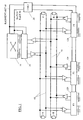
- Fig. 1 is a block diagram of a Telecommunications system according to an embodiment of the present invention.
- LVDS Low Voltage Digital signaling
- the LVDS is a fast serial method Data transmission with low input power for example over copper lines.
- the advantages of For example, LVDS procedures are low Noise and low crosstalk between neighboring lines due to lower Working voltages.
- An insert is both simple Point-to-point connections as well as so-called Multidrop connections, i.e. Connections between one Transmitter and multiple receivers possible. In the latter In this case, however, certain requirements must be met (e.g. appropriate drivers, low Input capacity).
- In the LVDS procedure for one direction (sending or receiving) two each Wires (wires or the like) are used that over Terminating resistors (R) to a line loop are connected.
- reference numeral 10 denotes one Coupling device or a switching matrix one Telecommunications system.
- the coupling device 10 serves in addition, signals or data in the telecommunications system to convey transparently and to different assemblies connect through the telecommunications system.
- Reference numeral 20 designates one with the Coupling device 10 connected transmission unit.
- the Transmission unit 20 transmitted and processed in suitably signals that go to and from the Coupling device 10 are sent.
- the coupling device 10 and the transmission unit 20 are connected to a clock generator 30.
- the clock generating device 30 provides a frame clock 40 and a data clock 50 ready.
- the frame rate 40 gives a time window for the transmission of data packets before, during the data clock the transfer rate within of the time window. Examples of numerical values are for the frame clock 8 kHz (corresponds to a time window of 125 ⁇ s) and for the data clock 4096 kHz, whereby it can be seen that other clock values are also set could be.
- the transmission unit 20 is via driver stages (Amplifier) with a pair of lines 60 and one Line pair 70 connected.
- Line pairs 60 and 70 each include 2 lines that are suitable over dimensioned terminating resistors R conductor loops form. Place the line pairs 60 and 70 Transmission lines, the transmission line 60 for the transmission of signals from the coupling device 10 and the transmission unit 20 and serves Transmission line 70 for the transmission of signals the coupling device 10 and the transmission unit 20 serves.
- the transmission lines uses the LVDS method described above.
- Peripheral devices P1, P2, P3 via driver stages (Amplifier) connected. Furthermore, the Peripherals P1, P2, P3 to the Clock generator 30 connected to the Frame clock 40 and the data clock 50 provides.
- the Peripheral devices P1, P2, P3 include modules for connecting End devices and connecting lines to public and private networks and the like.
- the Peripheral devices P1, P2, P3 transmission units 120 which is used to connect the peripheral devices to the Transmission lines 60 and 70 of Serve telecommunications system.
- the transmission units 20 and 120 shown, eight instructions and guidelines each comprehensive connections provide the to be transmitted Highways of the telecommunications system.
- FIG Telecommunications system in addition to those shown other, commonly known devices and assemblies includes, such as a power supply, Control devices and the like. These are for Simplify the presentation of the Telecommunications system and the invention omitted.
- FIG. 2 is a more detailed representation of the Transmission unit 20 shown in FIG. 1.
- the transmission unit 20 of the coupling device 10 includes processing devices 210 and 220 and one Control device 230.
- the control device 230 is with the processing devices 220, 230 and the driver stages for sending and receiving to / from the Transmission unit 20 of the coupling device 10 connected. Furthermore, the control device 230 the frame clock 40 and the data clock 50 supplied.
- the processing device 210 is set up for Transmission from the coupling device 10 to the Transmission line 60 suitably certain data to process. That is, it changes from the Coupling device coming parallel (P) data strings or highways (in Fig. 2 eight supply lines) in Frames around (allocating a data string to a transmission block, compressing the data, Add auxiliary information) and assigns it a serial transmission block set (S). The Block transfer is then made to the driver via a driver Transmission line 60 sent.
- P parallel
- S serial transmission block set
- the processing device 220 set up a serial burst of the transmission line 70 (i.e. from the Peripheral devices P1, P2, P3) via a driver received and processed. That is, it processes existing in the serial frame set Transmission blocks in parallel data strings or Highways (splitting the transmission blocks and assigning them to data strands, removal of auxiliary information Decompress) to the coupling device 10 are forwarded (eight lines in Fig. 2).
- the control device 230 controls the in the Processing devices 210, 220 made Processing and switching the on and off involved drivers.
- the supplied Frame clock 40 and / or the supplied data clock 50 be used.
- the controller 230 is for example, set up the processing of received data strings and the received Transmission blocks by means of the frame clock synchronize (for example in a 125 ⁇ s Time window). That is, the controller 230 recognizes or generates (depending on whether received or is sent) a frame start and can thus the Beginning of a frame block with a specific one Determine the number of transmission blocks.
- additional Auxiliary information in the transmission blocks such as for example, certain switch bits enable a easy detection of the start of a transmission block (and thus of a highway).
- the structure and function of the transmission units 120 of the peripheral devices is essentially that similarly described above. Of course this is too note that received from the transmission line 60 and is sent to the transmission line 70. Of Another difference is that the corresponding Control devices and processing devices of the transmission units 120 only assigned to them Receive or send data strings (highways). Different expressed the control devices and Processing facilities of the transmission units 120 process only during one of the assigned Data strings corresponding part of the by the Frame clock 40 predetermined amount of time data, whereas Control device and processing devices of the Transmission unit 20 throughout the through which Process frame clock 40 predetermined time period data. For example, the transmission units 120 (or the peripheral devices P1, P2, P3) connected Drivers only turned on at these times.
- the control devices of the transmission units 20 and 120 can be designed as individual units, or in a single control device be brought together.
- the single control device can for example be part of a general Control device of the telecommunications system.
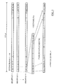
- 3 and 4 are in the system according to FIG transmitted data in a temporal representation demonstrated.
- FIG. 3 and 4 is based on a frame rate of 8 kHz (corresponds to one predetermined period of 125 ⁇ s) and a data clock assumed from 4096 kHz.
- Eight highways i.e. eight data strings
- On Data string comprises, for example, 64 bytes, which makes up a transmission rate per highway of 4,096 Mbps (megabits per sec.)
- FIG. 3 there are eight Data strands (highways 1 to 8) available in the system.
- the eight highways are connected to the eight feed lines of the Processing device 210 supplied.
- the processing device 210 now contains one Time (or a time slot) eight bytes (1/1 ... 8/1) in front.
- the successively arriving data in one (not shown) buffered. Is a predetermined period of 125 ⁇ s (i.e. one frame of the Frame clock) ended, lie in the Processing device 210 consequently pre-8 * 64 bytes.
- a predetermined period of 125 ⁇ s i.e. one frame of the Frame clock
- 64 bytes lie in the Processing device 210 consequently pre-8 * 64 bytes.
- Around in a corresponding time window transmitted (time division multiplex) is a compression of the Data required what is in the processing facility 210 is executed.
- the parallel received data of the individual data strands so composed that a complete data strand one Transmission block forms (1/1 ... 1/64; ...; 8/1 ... 8/64).
- the Data strands (or highways) compressed to the extent that in addition to the transmission blocks thus formed Auxiliary information in the predetermined period of 125 ⁇ s can be accommodated.
- compressed transmission block an equal predetermined Time period (for example 1/10 of the predetermined Duration of 125 ⁇ s).
- start information start bit, sync word
- the total length of a transmission block set results thus from the length of the (eight) compressed Transmission blocks and from the length of the added Start information and switch bits or fill bits.
- the processing device 210 set up a corresponding runtime compensation on End of a burst to add the to reach a predetermined value.
- the Peripherals can by means of their Transmission units 120 the transmission block set receive.
- the corresponding drivers preferably controlled so that only at times when those assigned highways or corresponding ones Frames in the predetermined period of 125 ⁇ s are present, the transmission unit 120 of the respective Peripheral device P1, P2, P3 receives.
- each peripheral device can be time-uncritical ready to receive (shown as corresponding reception phase of a peripheral device).
- the time control is done via the frame clock as well preferably that existing in the frame set Start information synchronized.
- the reception process in one of the transmission facilities 120 is the reverse of the broadcasting process Transmission unit 20. That is, a corresponding one Processing device of the transmission unit 120 removes auxiliary information (start information, fill bits) from the received data at an assigned Transmission block, decompresses the transmission block and thus receives the original data string (highway). This is then connected to a connected one, for example Terminal or the like forwarded.
- auxiliary information start information, fill bits
- the transmission sequence in the reverse direction (i.e. from the Peripherals P1, P2, P3 to the Coupling device 10) is carried out in a similar manner.
- the main difference is that the serial frame set sent from one Transmission unit 120 is generated, but in Interaction of all transmission units 120 generated becomes. That is, each transmission unit 120 also generates a corresponding processing device from a for example, data string received from a terminal a transmission block of a predetermined length. Switch bits or fill bits are added. additionally is one of the transmission units capable of Start information at the beginning of your transmission block add (e.g. peripheral device P1).
- each has the equivalent of the reception phases Peripheral device associated with a highway Send phase to, to which you send the transmission block can. There is preferably only one at a time Peripheral device active as a sending device to To avoid interference in the transmission.
- a serial becomes on the transmission line 70 Justification by the successive Transmission blocks by the Peripheral devices P1, P2, P3 are formed.
- This Block of transmission is performed by the transmission unit 20 the coupling device 10 completely received and evaluated. That is, the frame justification by the processing device 220 with the aid the switch bits divided into the transmission blocks, the auxiliary information is removed and the Transmission blocks become the data strands decompressed. The data strands (highways) are forwarded in parallel to the coupling device 10, in the corresponding processing (mediation, Resorting). Then be the resorted records from the coupling device forwarded to the processing device 210.
- the coupling device sends and receives on all highways (eight highways 1), while the peripheral modules each only send on the assigned highways or receive.
- Allocating the highways to Peripheral devices can according to FIG. 1 by means of a Software setting by a (not shown) Control device take place. That is, the assignment can be fixed (a certain highway is always one assigned to certain peripheral device) or be flexible (a highway is sequential assigned to different peripheral devices). It is also possible that only a single Highway is assigned to a peripheral device, or that multiple highways of a peripheral device assigned. This is for example with the Dashed line in the peripheral device P3 displayed. Furthermore, a highway on the receiving side or several highways simultaneously from several Peripheral devices are received (multidrop system).
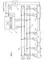
- FIG. 5 is a modification of that shown in FIG. 1 Systems shown. Identify the same reference numerals same elements, and for a more detailed description is omitted here.
- Peripheral devices P1 *, P2 *, P3 * each comprise a transmission unit 121.
- the structure of the transmission unit 121 is in the Substantially equivalent to that in connection with FIG. 2 described structure.
- the difference is the Allocation of the highways in the peripheral devices not by a control device using software, but the assignment is fixed by means of Hardware setting coded (e.g. Highway 2 is always read from slot 2). That is, the Transmission unit 121 only has an outgoing line and a signpost for a highway. This simplifies the system structure and enables one cost-effective implementation of the system.
- a further increase in bandwidth i.e. a Transmission of more data strands or highways or of Highways with a higher data rate (data clock), as well possible as a reduction in the number of required data lines.
- This can be done by repeated Doubling the transmission rate and transmission of the Send and receive data (from the point of view of Coupling device) take place in time-division multiplexing.
- the attainable upper limit is determined by the conditions in System or in the telecommunication system (i.e. for example by performance limits and number of used plug system and the cable routing and the like) and by the drivers used and Recipient (i.e. for example by the Driver performance, through the capacitive Load, due to the cable length and the like) certainly.
- the evaluation after detection the start time (start bits, switch bits, Time measurement) at an ideal sampling time also at enable very short bit lengths.
- LVDS is called Transmission method used. However, it is the same possible to use a different transmission method that enables fast serial data transmission.
- the data in the Telecommunication system between peripheral devices 120, P1, P2, P3 via a coupling device 10, 20 transmitted by means of a transmission connection 60, 70 be and a data clock 50 and a frame clock 40 for the timing of the transmission of the data are provided with the steps of processing Data strings to blocks, serial transmission the transmission blocks on the transmission link, Receive the serial frames and Process the received frames parallel data strings, rearranging the parallel Data strands and processing of the rearranged Data strings to new transmission blocks and serial Sending the new frames on the Transmission link.
- a corresponding system proposed.
Landscapes
- Engineering & Computer Science (AREA)
- Computer Networks & Wireless Communication (AREA)
- Signal Processing (AREA)
- Data Exchanges In Wide-Area Networks (AREA)
Abstract
Description
Die vorliegende Erfindung betrifft ein Verfahren sowie ein System zur Übertragung von Daten, und insbesondere ein Verfahren sowie ein System zur Übertragung von Daten in einer Telekommunikationsanlage.The present invention relates to a method as well a system for data transmission, and in particular a method and a system for the transmission of data in a telecommunication system.
Zur schnellen Übertragung von Sprachdaten in Telekommunikationsanlagen, in PC-basierten Sprachverarbeitungsbaugruppen und dergleichen werden beispielsweise sogenannte Highways als Übertragungsmedium verwendet. Die Sprachdaten werden dabei beispielsweise als PCM-codierte (PCM: Pulscodemodulation) digitale Daten übertragen.For fast transmission of voice data in Telecommunication systems, in PC-based Speech processing assemblies and the like for example so-called highways as a transmission medium used. The voice data are, for example as PCM-encoded (PCM: pulse code modulation) digital data transfer.
Ein Highway umfasst im Wesentlichen drei Leitungsarten. Eine Leitung dient zur Bereitstellung eines Datentaktes (engl.: data clock), beispielsweise 2, 4, 8 oder 16 x 1024 kHz. Eine weitere Leitung dient zur Bereitstellung eines Rahmentakts (engl.: frame clock), beispielsweise 8 kHz. Die dritte Leitungsart dient zur Übertragung der eigentlichen Daten. Es ist zumindest eine Übertragungsleitung vorgesehen. Meistens werden für die Senderichtung und die Empfangsrichtung in einem Telekommunikationssystem jeweils eine Übertragungsleitung verwendet. In einem Zeitfenster von 125 µs (entsprechend einem Rahmentakt von 8 kHz) und bei einer Übertragung von 512 Bit (→ 64 Byte) ergibt sich beispielsweise eine Übertragungsrate von 4096 kbps (Kilobit pro Sekunde) (Datentakt von 4 x 1024 kHz). A highway essentially comprises three types of lines. A line is used to provide a data clock (English: data clock), for example 2, 4, 8 or 16 x 1024 kHz. Another line is used for provision a frame clock, for example 8 kHz. The third type of line is used to transmit the actual data. It is at least one Transmission line provided. Mostly for Sending direction and the receiving direction in one Telecommunications system each have a transmission line used. In a time window of 125 µs (accordingly a frame rate of 8 kHz) and with a transmission of For example, 512 bits (→ 64 bytes) results in one Transmission rate of 4096 kbps (kilobits per second) (Data clock rate of 4 x 1024 kHz).
Zur Abdeckung der in der Telekommunikationsanlage geforderten Übertragungskapazität wird beispielsweise die entsprechende Anzahl von verwendeten Datenleitungen vergrößert, um das erforderliche Vielfach der Übertragungsrate zu erreichen. Je nach Größe des System (Anzahl der Teilnehmer) oder Menge und Art der zu übertragenden Daten (Sprachdaten, andere Daten (Video oder dergleichen)) kann die Anzahl von erforderlichen Datenleitungen relativ groß werden. So werden in einem Bus nach dem von dem Enterprise Computer Telephony Forum (ECTF) definierten Standards H.100/H.110 beispielsweise 32 Datenleitungen verwendet.To cover the in the telecommunications system required transmission capacity is, for example corresponding number of data lines used enlarged to the required multiple of To achieve transmission rate. Depending on the size of the system (Number of participants) or amount and type of to transmitting data (voice data, other data (video or the like)) may be the number required Data lines become relatively large. So in one Bus to that from the Enterprise Computer Telephony Forum (ECTF) defined standards H.100 / H.110 for example 32 data lines used.
Eine weitere Möglichkeit zur Steigerung der Bandbreite, d.h. der Datenübertragungsrate des Systems ist, den Datentakt zu steigern. Dies ist beispielsweise durch den Einsatz entsprechender Bustechnologien möglich, wie BTL (Bus Transceiver Logic) oder GTL (Gunning Transceiver Logic). Hiermit sind Datentakte weit über den vorstehend genannten, in herkömmlichen Telekommunikationsanlagen verwendeten Datentakten (bis zu 16 x 1024 kHz) möglich. Dazu ist es jedoch erforderlich, die anderen Bausteine und Komponenten der Telekommunikationsanlage (beispielsweise Treiber, Leitungslänge und dergleichen) an die hohe Datentaktrate anzupassen, d.h. es sind Komponenten erforderlich, die den hohen Datentakt verarbeiten können.Another way to increase bandwidth, i.e. is the data transfer rate of the system Increase data clock. This is for example through the Appropriate bus technologies can be used, such as BTL (Bus Transceiver Logic) or GTL (Gunning Transceiver Logic). Hereby data clocks are far above the above mentioned, in conventional telecommunications systems data clocks used (up to 16 x 1024 kHz) possible. However, this requires the other building blocks and components of the telecommunications system (e.g. driver, cable length and the like) to adapt to the high data clock rate, i.e. there are Components required that the high data clock can process.
Eine Aufgabe der vorliegenden Erfindung besteht darin, ein verbessertes Verfahren und/oder System zur Datenübertragung, insbesondere in einer Telekommunikationsanlage, bereitzustellen. An object of the present invention is an improved method and / or system for Data transmission, especially in a Telecommunications system to provide.
Diese Aufgabe wird beispielsweise gelöst durch ein Verfahren zum Übertragen von Daten in einer Telekommunikationsanlage, wobei die Daten in der Telekommunikationsanlage zwischen Peripherievorrichtungen über eine Koppelvorrichtung mittels einer Übertragungsverbindung übertragen werden und ein Datentakt sowie ein Rahmentakt für die zeitliche Steuerung der Übertragung der Daten bereitgestellt sind, mit den Schritten Verarbeiten von Datensträngen zu Übertragungsblöcken serielles Senden der Übertragungsblöcke auf der Übertragungsverbindung, Empfangen der seriellen Übertragungsblöcke und Verarbeiten der empfangenen Übertragungsblöcke zu parallelen Datensträngen, Umordnen der parallelen Datenstränge und Verarbeiten der umgeordneten Datenstränge zu neuen Übertragungsblöcken und serielles Senden der neuen Übertragungsblöcke auf der Übertragungsverbindung.This problem is solved, for example, by a Process for transferring data in a Telecommunications system, the data in the Telecommunication system between peripheral devices via a coupling device by means of a Transmission link to be transmitted and a Data clock as well as a frame clock for the temporal Control the transmission of data are provided with the steps of processing data strings Transmission blocks serial transmission of the Transmission blocks on the transmission link, Receive the serial frames and Process the received frames parallel data strings, rearranging the parallel Data strands and processing of the rearranged Data strings to new transmission blocks and serial Sending the new frames on the Transmission link.
Ferner wird die Aufgabe beispielsweise gelöst durch ein System zur Übertragung von Daten in einer Telekommunikationsanlage, mit einer Vielzahl von Peripherievorrichtungen zum Senden und Empfangen von Daten, einer Koppelvorrichtung zum Weiterleiten und Verarbeiten der Daten, einer Takterzeugungsvorrichtung zur Erzeugung eines Datentakts sowie eines Rahmentakts für die zeitliche Steuerung der Übertragung der Daten und einer Übertragungsverbindung, wobei die Peripherievorrichtungen eingerichtet sind, einen zu sendenden Datenstrang in einen Übertragungsblock zu verarbeiten und den Übertragungsblock auf der Übertragungsverbindung zu der Koppelvorrichtung zu senden, und die Koppelvorrichtung eingerichtet ist, eine Vielzahl von Übertragungsblöcken zu empfangen und diese zu parallelen Datensträngen zu verarbeiten, die parallelen Datenstränge umzuordnen und neue Übertragungsblöcke aus den umgeordneten Datensträngen zu bilden sowie die neuen Übertragungsblöcke seriell auf der auf der Übertragungsverbindung zu den Peripherievorrichtungen zu senden.Furthermore, the task is solved, for example, by a System for the transmission of data in one Telecommunications system, with a variety of Peripherals for sending and receiving Data, a coupling device for forwarding and Processing the data, a clock generator to generate a data clock and a frame clock for timing the transmission of data and a transmission link, the Peripherals are set up to one sending data string in a transmission block process and the transmission block on the Transmission connection to the coupling device send, and the coupling device is set up, a Variety of frames and receive them to process parallel data strings that rearrange parallel data strings and new ones Transmission blocks from the rearranged data strings too form as well as the new transmission blocks serially on the on the transmission link to the To send peripheral devices.
Weitere vorteilhafte Ausgestaltungen der Erfindung sind in den jeweiligen abhängigen Patentansprüchen angeführt.Further advantageous embodiments of the invention are cited in the respective dependent claims.
Mittels des erfindungsgemäßen Verfahrens bzw. des erfindungsgemäßen Systems ist es möglich, auf der Peripherievorrichtungsseite zumindest einen Datenstrang durch eine entsprechende Verarbeitungseinrichtung einzulesen, diesen zu komprimieren und einen so erzeugten Übertragungsblock bei einem vorbestimmten Zeitpunkt über die Übertragungsleitung zu senden. Der Übertragungsblock weist dabei eine erste vorbestimmte Zeitdauer auf. Die Zeitsteuerung kann mittels einer Steuerungseinrichtung und den systeminternen Daten- bzw. Rahmentakten erfolgen.By means of the method according to the invention or system according to the invention it is possible on the Peripheral device side at least one data string by an appropriate processing device read in, compress it and create a generated Frame over at a predetermined time to send the transmission line. The transmission block has a first predetermined period of time. The Time control can be done by means of a control device and the system-internal data or frame clocks.
Senden mehrere unterschiedliche Peripherievorrichtungen zu jeweils unterschiedlichen Zeitpunkten in einer zweiten vorbestimmten Zeitdauer, wird auf der Übertragungsverbindung ein Übertragungsblocksatz gebildet, der mehrere seriell angeordnete Übertragungsblöcke umfasst. Dieser Übertragungsblocksatz wird in der Koppelvorrichtung während einer zweiten vorbestimmten Zeitdauer über eine Verarbeitungseinrichtung eingelesen. Die Übertragungsblöcke werden dekomprimiert und die Datenstränge der einzelnen Peripherievorrichtungen werden parallel wiederhergestellt. Die Unterscheidung der Datenstränge (bzw. der Übertragungsblöcke) kann mittels einer mit den systeminternen Daten- bzw. Rahmentakten gekoppelten Steuerungseinrichtung erfolgen. Send several different peripheral devices at different times in a second predetermined period of time, is on the Transmission link a frame set formed, the several serially arranged Transmission blocks. This frame justification is in the coupling device during a second predetermined period of time over a Processing device read. The Blocks are decompressed and the Data strands of the individual peripheral devices restored in parallel. The distinction of Data strands (or the transmission blocks) can be created using one with the system-internal data or frame clocks coupled control device.
In der Koppelvorrichtung werden die Datenstränge zwischengespeichert und entsprechend umsortiert, so dass eine Vermittlung eines von einer Peripherievorrichtung stammenden Datenstrangs zu einer anderen Peripherievorrichtung erfolgt. Das heißt, die zeitliche Anordnung der Datenstränge wird so geordnet, dass ihnen jeweils eine Empfangszeit der Empfangs-Peripherievorrichtung zugeordnet ist. Die Datenstränge werden komprimiert, um neue Übertragungsblöcke entsprechend der Umordnung der Datenstränge zu erzeugen. Die neuen Übertragungsblöcke weisen wiederum die erste vorbestimmte Zeitdauer auf. Dann werden die neuen Übertragungsblöcke zu einem neuen Übertragungsblocksatz einer zweiten vorbestimmten Zeitdauer angeordnet und auf der Übertragungsleitung gesendet. Die Komprimierung der Datensätze und die Bildung des Übertragungsblocksatzes erfolgt beispielsweise mittels einer Verarbeitungseinrichtung und einer Steuerungseinrichtung.The data strands are in the coupling device cached and rearranged accordingly so that switching one from a peripheral device originating data string to another Peripheral device takes place. That is, the temporal Arrangement of the data strands is arranged so that they each a reception time of the reception peripheral device assigned. The data strands are compressed to new frames to generate according to the reordering of the data strands. The new transmission blocks in turn have the first predetermined period of time. Then the new ones Frames to a new frame set arranged a second predetermined period of time and on the transmission line. The compression of the Records and the formation of the transmission justification takes place, for example, by means of a Processing device and a control device.
Bei einem Übertragungsblock werden beispielsweise bestimmte Startinformationen eingefügt, um den Beginn eines Übertragungsblocksatzes anzuzeigen. Hierdurch kann eine Identifikation und somit die Verarbeitung eines Übertragungsblockssatzes in dem seriellen Datenstrom verbessert werden. In Verbindung mit beispielsweise dem systeminternen Rahmentakt kann so die Übertragung synchronisiert werden.For example, in a transmission block certain start information inserted to start of a transmission block set. This can an identification and thus the processing of a Block set in the serial data stream be improved. In connection with, for example, the system-internal frame rate can thus transfer be synchronized.
Ferner können zwischen jeweiligen Übertragungsblöcken Zusatzinformationen für ein Umschalten zwischen den Übertragungsblöcken eingefügt werden. Hierdurch kann gewährleistet werden, dass ein zeitunkritisches Umschalten zwischen Übertragungsblöcken möglich ist, was durch Hinzufügen von Umschaltbits bzw. bedeutungsloser Füllbits einfach erreicht wird.Furthermore, between respective transmission blocks Additional information for switching between the Transfer blocks are inserted. This can ensure that a time-uncritical Switching between frames is possible by adding toggle bits or meaningless Fill bits is easily achieved.
Des Weiteren können zwischen Übertragungsblocksätzen Zusatzinformationen eingefügt werden, um die Zeitdauer eines Übertragungsblocksatzes auf einen zweiten vorbestimmten Wert zu vergrößern. Hierdurch kann gewährleistet werden, dass die Übertragungsblocksätze immer die zweite vorbestimmte Zeitdauer umfassen, was durch Hinzufügen bedeutungsloser Füllbits einfach erreicht wird.Furthermore, you can choose between transmission block sets Additional information can be added to the duration a transmission block set to a second increase predetermined value. This can ensure that the transmission block sets always include the second predetermined period of time simply by adding meaningless fill bits is achieved.
Vorteilhafterweise sendet immer nur eine Peripherievorrichtung zu einem Zeitpunkt in der vorbestimmten zweiten Zeitdauer einen Übertragungsblock. Hierdurch kann ein störungsfreies Übertragen in dem System erreicht werden.Advantageously only ever sends one Peripheral device at a time in the predetermined second time a transmission block. This allows interference-free transmission in the System can be achieved.
Die Peripherievorrichtung kann beispielsweise ausgelegt sein, dass immer nur ein Übertragungsblock in einem Übertragungsblocksatz empfangen wird. Es ist aber ebenso möglich, dass mehr als ein Übertragungsblock in einem Übertragungsblocksatz empfangen werden kann. Die Übertragungsblöcke können dabei aufeinanderfolgend sein oder durch Übertragungsblöcke unterbrochen sein, die von anderen Peripherievorrichtungen empfangen werden.The peripheral device can be designed, for example be that only one transmission block at a time Frame block is received. But it is the same possible that more than one frame in one Frame rate can be received. The Transmission blocks can be consecutive or be interrupted by blocks of data from other peripheral devices can be received.
Ein Übertragungsblock kann zu einem Zeitpunkt von einer Peripherievorrichtung empfangen werden, oder gleichzeitig von mehreren Peripherievorrichtungen. Hierdurch kann ein Multidrop-System (ein Sender, mehrere Empfänger) realisiert werden. A transmission block can be transferred from one to a time Peripheral device can be received, or simultaneously of several peripheral devices. This can be a Multidrop system (one transmitter, several receivers) will be realized.
Als Übertragungsverfahren kann beispielsweise ein LVDS-Verfahren (Low Voltage Digital Signaling) verwendet werden.An LVDS method, for example, can be used as the transmission method (Low Voltage Digital Signaling) used become.
Vorteilhafterweise kann durch Verwendung des erfindungsgemäßen Verfahrens und/oder des erfindungsgemäßen Systems die in einer Telekommunikationsanlage verfügbare Bandbreite (bzw. Übertragungsrate) gesteigert werden, ohne dass hierfür zusätzliche Leitungen erforderlich sind. Dies wird erreicht, indem ein schnelles serielles Übertragungsverfahren in der Telekommunikationsanlage zur Übertragung von parallel vorliegenden Datensträngen (Highways) eingesetzt wird (beispielsweise Zeitmultiplex-Verfahren).Advantageously, by using the inventive method and / or system according to the invention in a Telecommunication system available bandwidth (or Transmission rate) can be increased without this additional lines are required. this will achieved by a fast serial Transmission process in the telecommunications system for Transmission of parallel data strings (Highways) is used (for example time division multiplexing).
Ferner ist es möglich, die Kompatibilität mit herkömmliche Baugruppen bzw. Komponenten in der Telekommunikationsanlage beizubehalten. Der Datentakt in der Telekommunikationsanlage wird im Vergleich zu herkömmlichen Telekommunikationsanlagen nicht erhöht und somit sind keine besonderen Komponenten für höhere Datentaktraten erforderlich.It is also possible to be compatible with conventional assemblies or components in the Maintain telecommunications system. The data clock in the telecommunications system is compared to conventional telecommunications systems are not increased and thus there are no special components for higher ones Data clock rates required.
Bei bereits bestehenden Telekommunikationsanlagen ist ein "Aufsplitten" der vorhandenen Leitungen und Anschlüsse einer Backplane der Telekommunikationsanlage möglich. Das heißt, die Bandbreite kann auf einfache Weise erhöht werden, indem die vorhandenen Leitungen aufgeteilt werden und das erfindungsgemäße Verfahren/System mit den jeweiligen Leitungsteilen als Übertragungsleitungen angewendet wird. So ist eine Vervielfachung der Bandbreite möglich, ohne dass neue Leitungen hinzugefügt werden müssen. In the case of existing telecommunications systems, a "Splitting" of the existing lines and connections a backplane of the telecommunications system possible. The that is, the bandwidth can be easily increased by dividing the existing lines and the inventive method / system with the respective line parts as transmission lines is applied. So is a multiplication of the Bandwidth possible without adding new lines Need to become.
Ebenso ist es möglich, bei Beibehaltung der Bandbreite die Anzahl der Datenleitungen entsprechend zu vermindern. Zusätzlich kann ein Stecksystem zur physikalischen Verbindung der Leitungen und/oder Komponenten verwendet werden, das eine geringere Anzahl von Polen aufweist als in einer herkömmlichen Telekommunikationsanlage gleicher Bandbreite.It is also possible to keep the bandwidth reduce the number of data lines accordingly. In addition, a plug-in system for physical Connection of lines and / or components used which has a smaller number of poles than the same in a conventional telecommunications system Bandwidth.
Die Erfindung wird nachstehend anhand von
Ausführungsbeispielen unter Bezugnahme auf die Zeichnung
näher beschrieben. Es zeigen:
In Fig. 1 ist ein Blockschaltbild einer Telekommunikationsanlage gemäß einem Ausführungsbeispiel der vorliegenden Erfindung gezeigt. In Fig. 1 is a block diagram of a Telecommunications system according to an embodiment of the present invention.
In der Telekommunikationsanlage gemäß Fig. 1 wird als Beispiel ein sogenanntes LVDS-Verfahren (Low Voltage Digital Signaling) zur Datenübertragung verwendet. Das LVDS-Verfahren ist ein Verfahren zur schnellen seriellen Datenübertragung bei geringer Eingangsleistung beispielsweise über Kupferleitungen. Die Vorteile des LVDS-Verfahrens liegen beispielsweise in einem niedrigem Rauschen und einem geringen Übersprechen zwischen benachbarten Leitungen aufgrund niedriger Arbeitsspannungen. Ein Einsatz ist sowohl bei einfachen Punkt-zu-Punkt-Verbindungen als auch bei sogenannten Multidrop-Verbindungen, d.h. Verbindungen zwischen einem Sender und mehreren Empfängern möglich. Im letztgenannten Fall sind jedoch bestimmte Voraussetzungen zu erfüllen (beispielsweise entsprechende Treiber, geringe Eingangskapazitäten). Bei dem LVDS-Verfahren werden für eine Richtung (Senden bzw. Empfangen) jeweils zwei Leitungen (Drähte oder dergleichen) verwendet, die über Abschlusswiderstände (R) zu einer Leitungsschleife verbunden sind.1 is used as Example of a so-called LVDS process (Low Voltage Digital signaling) used for data transmission. The LVDS is a fast serial method Data transmission with low input power for example over copper lines. The advantages of For example, LVDS procedures are low Noise and low crosstalk between neighboring lines due to lower Working voltages. An insert is both simple Point-to-point connections as well as so-called Multidrop connections, i.e. Connections between one Transmitter and multiple receivers possible. In the latter In this case, however, certain requirements must be met (e.g. appropriate drivers, low Input capacity). In the LVDS procedure, for one direction (sending or receiving) two each Wires (wires or the like) are used that over Terminating resistors (R) to a line loop are connected.
In Fig. 1 bezeichnet Bezugszeichen 10 eine
Koppelvorrichtung bzw. ein Koppelfeld einer
Telekommunikationsanlage. Die Koppelvorrichtung 10 dient
dazu, Signale bzw. Daten in der Telekommunikationsanlage
transparent zu vermitteln und zu verschiedenen Baugruppen
der Telekommunikationsanlage durchzuschalten.In Fig. 1,
Bezugszeichen 20 bezeichnet eine mit der
Koppelvorrichtung 10 verbundene Übertragungseinheit. Die
Übertragungseinheit 20 übertragt und verarbeitet in
geeigneter Weise Signale, die zu und von der
Koppelvorrichtung 10 gesendet werden.
Die Koppelvorrichtung 10 und die Übertragungseinheit 20
sind mit einer Takterzeugungseinrichtung 30 verbunden.
Die Takterzeugungseinrichtung 30 stellt einen Rahmentakt
40 sowie einen Datentakt 50 bereit. Der Rahmentakt 40
gibt ein Zeitfenster für die Übertragung von Datenpaketen
vor, während der Datentakt die Übertragungsrate innerhalb
des Zeitfensters bestimmt. Beispiele für Zahlenwerte sind
für den Rahmentakt 8 kHz (entspricht einem Zeitfenster
von 125 µs) und für den Datentakt 4096 kHz, wobei
ersichtlich ist, dass auch andere Taktwerte eingestellt
sein können.The
Die Übertragungseinheit 20 ist über Treiberstufen
(Verstärker) mit einem Leitungspaar 60 und einem
Leitungspaar 70 verbunden. Die Leitungspaare 60 und 70
umfassen jeweils 2 Leitungen, die über geeignet
dimensionierte Abschlusswiderstände R Leiterschleifen
bilden. Die Leitungspaare 60 und 70 stellen
Übertragungsleitungen dar, wobei die Übertragungsleitung
60 zur Übertragung von Signalen von der Koppelvorrichtung
10 und der Übertragungseinheit 20 dient und die
Übertragungsleitung 70 zur Übertragung von Signalen zu
der Koppelvorrichtung 10 und der Übertragungseinheit 20
dient. Für die Übertragungsleitungen wird beispielsweise
das vorstehend beschriebene LVDS-Verfahren verwendet.The
An die Übertragungsleitungen 60 und 70 sind
Peripherievorrichtungen P1, P2, P3 über Treiberstufen
(Verstärker) angeschlossen. Ferner sind die
Peripherievorrichtungen P1, P2, P3 an die
Takterzeugungseinrichtung 30 angeschlossen, die den
Rahmentakt 40 und den Datentakt 50 bereitstellt. Die
Peripherievorrichtungen P1, P2, P3
umfassen beispielsweise Baugruppen zum Anschluss von
Endgeräten und Verbindungsleitungen zu öffentlichen und
privaten Netzen und dergleichen. Ferner umfassen die
Peripherievorrichtungen P1, P2, P3 Übertragungseinheiten
120, die zur Anbindung der Peripherievorrichtungen an die
Übertragungsleitungen 60 und 70 der
Telekommunikationsanlage dienen. Dabei dient die
Übertragungsleitung 60 zur Übertragung von Signalen zu
den jeweiligen Peripherievorrichtungen P1, P2, P3 und die
Übertragungsleitung 70 zur Übertragung von den jeweiligen
Peripherievorrichtungen P1, P2, P3. Es ist zu beachten,
dass zur Vereinfachung lediglich drei
Peripherievorrichtungen dargestellt sind. Es ist jedoch
möglich, weitere Peripherievorrichtungen in das System
hinzuzufügen.To the
Die bei den Übertragungseinheiten 20 und 120
dargestellten, jeweils acht Hinleitungen und Wegleitungen
umfassenden Verbindungen stellen die zu übertragenden
Highways der Telekommunikationsanlage dar.The
Es ist ersichtlich, dass die in Fig. 1 gezeigte Telekommunikationsanlage neben den gezeigten auch noch andere, allgemein bekannte Vorrichtungen und Baugruppen umfasst, wie beispielsweise eine Energieversorgung, Steuerungsvorrichtungen und dergleichen. Diese sind zur Vereinfachung der Darstellung der Telekommunikationsanlage sowie der Erfindung weggelassen.It can be seen that the one shown in FIG Telecommunications system in addition to those shown other, commonly known devices and assemblies includes, such as a power supply, Control devices and the like. These are for Simplify the presentation of the Telecommunications system and the invention omitted.
In Fig. 2 ist eine ausführlichere Darstellung der
Übertragungseinheit 20 gemäß Fig. 1 gezeigt.2 is a more detailed representation of the
Die Übertragungseinheit 20 der Koppelvorrichtung 10
umfasst Verarbeitungseinrichtungen 210 und 220 sowie eine
Steuerungseinrichtung 230. Die Steuerungseinrichtung 230
ist mit den Verarbeitungseinrichtungen 220, 230 sowie mit
den Treiberstufen zum Senden und Empfangen zu/von der
Übertragungseinheit 20 der Koppelvorrichtung 10
verbunden. Des Weiteren werden der Steuerungseinrichtung
230 der Rahmentakt 40 sowie der Datentakt 50 zugeführt.The
Die Verarbeitungseinrichtung 210 ist eingerichtet, zur
Übertragung von der Koppelvorrichtung 10 zu der
Übertragungsleitung 60 bestimmte Daten geeignet zu
verarbeiten. Das heißt, sie wandelt von der
Koppelvorrichtung kommende parallele (P) Datenstränge
bzw. Highways (in Fig. 2 acht Zufuhrleitungen) in
Übertragungsblöcke um (Zuordnen eines Datenstrangs zu
einem Übertragungsblock, Komprimieren der Daten,
Hinzufügen von Hilfsinformationen) und ordnet diese zu
einem seriellen Übertragungsblocksatz (S) an. Der
Übertragungsblocksatz wird dann über einen Treiber zu der
Übertragungsleitung 60 gesendet.The
Demgegenüber ist die Verarbeitungseinrichtung 220
eingerichtet, einen seriellen Übertragungsblocksatz von
der Übertragungsleitung 70 (d.h. von den
Peripherievorrichtungen P1, P2, P3) über einen Treiber zu
empfangen und zu verarbeiten. Das heißt, sie verarbeitet
in dem seriellen Übertragungsblocksatz vorhandene
Übertragungsblöcke in parallele Datenstränge bzw.
Highways (Aufteilen der Übertragungsblöcke und Zuordnen
zu Datensträngen, Entfernen von Hilfsinformationen
Dekomprimieren), die zu der Koppelvorrichtung 10
weitergeleitet werden (in Fig. 2 acht Leitungen).In contrast, the
Die Steuerungseinrichtung 230 steuert die in den
Verarbeitungseinrichtungen 210, 220 vorgenommenen
Verarbeitungen sowie das Ein- und Ausschalten der
beteiligten Treiber. Hierzu können der zugeführte
Rahmentakt 40 und/oder der zugeführte Datentakt 50
verwendet werden. Die Steuerungseinrichtung 230 ist
beispielsweise eingerichtet, die Verarbeitung der
empfangenen Datenstränge und der empfangenen
Übertragungsblöcke mittels des Rahmentakts zu
synchronisieren (beispielsweise in einem 125 µs
Zeitfenster). Das heißt, die Steuerungseinrichtung 230
erkennt bzw. erzeugt (in Abhängigkeit davon, ob empfangen
oder gesendet wird) einen Rahmenbeginn und kann somit den
Beginn eines Übertragungsblocksatzes mit einer bestimmten
Anzahl von Übertragungsblöcken bestimmen. Zusätzliche
Hilfsinformationen bei den Übertragungsblöcken, wie
beispielsweise bestimmte Umschaltbits, ermöglichen ein
einfaches Erkennen des Beginns eines Übertragungsblocks
(und damit eines Highways).The
Der Aufbau und die Funktion der Übertragungseinheiten 120
der Peripherievorrichtungen ist im Wesentlichen dem
vorstehend beschriebenen ähnlich. Dabei ist natürlich zu
beachten, dass von der Übertragungsleitung 60 empfangen
wird und zu der Übertragungsleitung 70 gesendet wird. Des
Weiteren ist ein Unterschied, dass die entsprechenden
Steuerungseinrichtungen und Verarbeitungseinrichtungen
der Übertragungseinheiten 120 lediglich ihnen zugeordnete
Datenstränge (Highways) empfangen bzw. senden. Anders
ausgedrückt, die Steuerungseinrichtungen und
Verarbeitungseinrichtungen der Übertragungseinheiten 120
verarbeiten nur während eines den zugeordneten
Datensträngen entsprechenden Teils der durch den
Rahmentakt 40 vorgegebenen Zeitdauer Daten, wohingegen
Steuerungseinrichtung und Verarbeitungseinrichtungen der
Übertragungseinheit 20 während der gesamten, durch den
Rahmentakt 40 vorgegebenen Zeitdauer Daten verarbeiten.
Beispielsweise werden mit den Übertragungseinheiten 120
(bzw. den Peripherievorrichtungen P1, P2, P3) verbundenen
Treiber lediglich zu diesen Zeiten eingeschaltet. The structure and function of the
Die Steuerungseinrichtungen der Übertragungseinheiten 20
und 120 können als einzelne Einheiten ausgeführt sein,
oder aber in einer einzelnen Steuerungsvorrichtung
zusammengeführt sein. Die einzelne Steuerungsvorrichtung
kann beispielsweise Teil einer allgemeinen
Steuerungsvorrichtung der Telekommunikationsanlage sein.The control devices of the
Die Arbeitsweise des vorstehend unter Bezugnahme auf die Figuren 1 und 2 beschriebenen erfindungsgemäßen Systems und des erfindungsgemäßen Verfahrens ist nachstehend unter Bezugnahme auf die Figuren 3 und 4 näher beschrieben.The operation of the above with reference to the Figures 1 and 2 described system according to the invention and the method of the invention is as follows with reference to Figures 3 and 4 in more detail described.
In den Figuren 3 und 4 sind in dem System gemäß Fig. 1 zu übertragende Daten in einer zeitlichen Darstellung aufgezeigt.3 and 4 are in the system according to FIG transmitted data in a temporal representation demonstrated.
Bei dem in den Figuren 3 und 4 dargestellten Beispiel wird von einem Rahmentakt von 8 kHz (entspricht einer vorbestimmten Zeitdauer von 125 µs) und einem Datentakt von 4096 kHz ausgegangen. Es werden acht Highways (d.h. acht Datenstränge) in dem System übertragen. Ein Datenstrang umfasst beispielsweise 64 Byte, woraus sich eine Übertragungsrate pro Highway von 4,096 Mbps (Megabit pro sek.) ergibt.In the example shown in Figures 3 and 4 is based on a frame rate of 8 kHz (corresponds to one predetermined period of 125 µs) and a data clock assumed from 4096 kHz. Eight highways (i.e. eight data strings) are transmitted in the system. On Data string comprises, for example, 64 bytes, which makes up a transmission rate per highway of 4,096 Mbps (megabits per sec.)
Als "Startpunkt" für die weitere Beschreibung wird von
der Schnittstelle zwischen dem Koppelfeld 10 und der
Verarbeitungseinrichtung 210 der Übertragungseinheit 20
gemäß Fig. 2 ausgegangenAs a "starting point" for the further description is from
the interface between the switching
Wie es in Fig. 3 veranschaulicht ist, sind acht
Datenstränge (Highways 1 bis 8) in dem System vorhanden.
Die vorbestimmte Zeitdauer von 125 µs ist in 64
Zeitschlitze aufgeteilt, in denen jeweils ein Byte
(=8 Bit) untergebracht wird (1/1...1/64;...;8/1...8/64).
Die acht Highways werden über die acht Zuleitungen der
Verarbeitungseinrichtung 210 zugeführt.As illustrated in Figure 3, there are eight
Data strands (
In der Verarbeitungseinrichtung 210 liegen nun zu einem
Zeitpunkt (bzw. einem Zeitschlitz) acht Byte (1/1...8/1)
vor. Für die weitere Verarbeitung werden die
aufeinanderfolgend ankommenden Daten in einem (nicht
gezeigten) Speicher zwischengespeichert. Ist eine
vorbestimmte Zeitdauer von 125 µs (d.h. ein Rahmen des
Rahmentakts) beendet, liegen in der
Verarbeitungseinrichtung 210 folglich 8 * 64 Byte vor. Um
diese in einem entsprechenden Zeitfenster seriell zu
übertragen (Zeitpultiplex), ist eine Komprimierung der
Daten erforderlich, was in der Verarbeitungseinrichtung
210 ausgeführt wird. Dabei werden die parallel
empfangenen Daten der einzelnen Datenstränge so
zusammengesetzt, dass ein kompletter Datenstrang einen
Übertragungsblock bildet (1/1...1/64;...;8/1...8/64).The
In Fig. 4 ist der weitere Ablauf der erfindungsgemäßen Übertragung beschrieben. (Zur Verdeutlichung der Zusammenhänge ist die letzte Zeile aus Fig. 3 in der ersten Zeile der Fig. 4 wiederholt dargestellt.)4 is the further sequence of the invention Transmission described. (To illustrate the Connections is the last line from Fig. 3 in the 4 shown repeatedly.)
In dem hier veranschaulichten Beispiel werden die
Datenstränge (bzw. Highways) soweit komprimiert, dass
neben den hierdurch gebildeten Übertragungsblöcken noch
Hilfsinformationen in der vorbestimmten Zeitdauer von 125
µs untergebracht werden können. Dabei weist jeder
komprimierte Übertragungsblock eine gleiche vorbestimmte
Zeitdauer auf (beispielsweise 1/10 der vorbestimmten
Zeitdauer von 125 µs). Zu Beginn eines
Übertragungsblocksatzes (der in dem Beispiel 8
Übertragungsblöcke umfasst) wird durch die
Verarbeitungseinrichtung 210 vorzugsweise eine
Startinformation (Startbit, Synchronwort) eingefügt,
durch die in Verbindung mit dem Rahmentakt das System
synchronisiert werden kann. Zwischen einzelnen
Übertragungsblöcken werden durch die
Verarbeitungseinrichtung 210 Umschaltbits bzw.
bedeutungslose Füllbits hinzugefügt, durch die ein
genaues Zuordnen der Übertragungsblocks sowie ein
zeitunkritisches Umschalten der beteiligten Treiber
ermöglicht wird.In the example illustrated here, the
Data strands (or highways) compressed to the extent that
in addition to the transmission blocks thus formed
Auxiliary information in the predetermined period of 125
µs can be accommodated. Everyone knows
compressed transmission block an equal predetermined
Time period (for example 1/10 of the predetermined
Duration of 125 µs). At the beginning of a
Frame set (which in Example 8
Transmission blocks) is covered by the
Die Gesamtlänge eines Übertragungsblocksatzes ergibt sich
somit aus der Länge der (acht) komprimierten
Übertragungsblöcke und aus der Länge der hinzugefügten
Startinformation und Umschaltbits bzw. Füllbits. Damit
ein Übertragungsblocksatz der vorbestimmten Zeitdauer von
125 µs entspricht, ist die Verarbeitungseinrichtung 210
eingerichtet, einen entsprechenden Laufzeitausgleich am
Ende eines Übertragungsblocksatzes hinzuzufügen, um den
vorbestimmten Wert zu erreichen.The total length of a transmission block set results
thus from the length of the (eight) compressed
Transmission blocks and from the length of the added
Start information and switch bits or fill bits. In order to
a frame set of the predetermined period of
Corresponds to 125 µs, the
Durch die vorstehende Verarbeitung der parallelen Datenstränge kann eine Nutzdatenübertragungsrate von 8 * 64 Byte/125 µs = 32,788 Mbps erreicht werden.By processing the parallel above Data strands can have a user data transmission rate of 8 * 64 bytes / 125 µs = 32.788 Mbps can be achieved.
Die derart verarbeiteten Datenstränge (Highways) werden
nun über die Übertragungsleitung 60 als
Übertragungsblocksatz gesendet. Die
Peripherievorrichtungen können mittels ihrer
Übertragungseinheiten 120 den Übertragungsblocksatz
empfangen. Dabei sind die entsprechenden Treiber
vorzugsweise so gesteuert, dass nur zu Zeitpunkten, bei
denen zugeordnete Highways bzw. entsprechende
Übertragungsblöcke in der vorbestimmten Zeitdauer von 125
µs vorliegen, die Übertragungseinheit 120 der jeweiligen
Peripherievorrichtung P1, P2, P3 empfängt. Durch die
zwischen den Übertragungsblöcken eingefügten Umschaltbits
kann jede Peripherievorrichtung zeitunkritisch
empfangsbereit geschaltet werden (dargestellt als
entsprechende Empfangsphase einer Peripherievorrichtung).
Die Zeitsteuerung wird dabei über den Rahmentakt sowie
vorzugsweise die in dem Übertragungsblocksatz vorhandene
Startinformation synchronisiert.The data strings processed in this way (highways)
now over the
Der Empfangsablauf in einer der Übertragungseinrichtungen
120 ist umgekehrt zu dem Sendeablauf der
Übertragungseinheit 20. Das heißt, eine entsprechende
Verarbeitungseinrichtung der Übertragungseinheit 120
entfernt Hilfsinformationen (Startinformation, Füllbits)
aus den empfangenen Daten bei einem zugeordneten
Übertragungsblock, dekomprimiert den Übertragungsblock
und erhält so den ursprünglichen Datenstrang (Highway).
Dieser wird dann beispielsweise an ein angeschlossenes
Endgerät oder dergleichen weitergeleitet.The reception process in one of the
Der Sendeablauf in umgekehrter Richtung (d.h. von den
Peripherievorrichtungen P1, P2, P3 zu der
Koppelvorrichtung 10) erfolgt auf ähnliche Weise. Der
Unterschied ist dabei im Wesentlichen, dass der seriell
gesendete Übertragungsblocksatz nicht von einer
Übertragungseinheit 120 erzeugt wird, sondern im
Zusammenspiel aller Übertragungseinheiten 120 erzeugt
wird. Das heißt, jede Übertragungseinheit 120 erzeugt mit
einer entsprechenden Verarbeitungseinrichtung aus einem
beispielsweise von einem Endgerät empfangenen Datenstrang
einen Übertragungsblock einer vorbestimmten Länge.
Umschaltbits bzw. Füllbits werden hinzugefügt. Zusätzlich
ist eine der Übertragungseinheiten in der Lage, die
Startinformation am Anfang ihres Übertragungsblocks
hinzuzufügen (beispielsweise Peripherievorrichtung P1). The transmission sequence in the reverse direction (i.e. from the
Peripherals P1, P2, P3 to the
Coupling device 10) is carried out in a similar manner. The
The main difference is that the serial
frame set sent from one
Unter der Steuerung entsprechender
Steuerungseinrichtungen senden die jeweiligen
Übertragungseinheiten 120 ihren Teil des
Übertragungsblocksatzes zu einem bestimmten Zeitpunkt,
wobei die Steuerungseinrichtungen mittels des
Rahmentaktes synchronisiert werden. Anders ausgedrückt,
äquivalent zu den Empfangsphasen weist jede
Peripherievorrichtung eine einem Highway zugeordnete
Sendephase auf, zu der sie den Übertragungsblock senden
kann. Vorzugsweise ist zu einem Zeitpunkt immer nur eine
Peripherievorrichtung als Sendevorrichtung aktiv, um
Störungen in der Übertragung zu vermeiden.Under the control of appropriate
Control devices send the
Auf der Übertragungsleitung 70 wird so ein serieller
Übertragungsblocksatz durch das aufeinanderfolgende
Senden der Übertragungsblöcke durch die
Peripherievorrichtungen P1, P2, P3 gebildet. Dieser
Übertragungsblocksatz wird von der Übertragungseinheit 20
der Koppelvorrichtung 10 vollständig empfangen und
ausgewertet. Das heißt, der Übertragungsblocksatz wird
durch die Verarbeitungseinrichtung 220 unter Zuhilfenahme
der Umschaltbits in die Übertragungsblöcke aufgeteilt,
die Hilfsinformationen werden entfernt und die
Übertragungsblöcke werden zu den Datensträngen
dekomprimiert. Die Datenstränge (Highways) werden
parallel zu der Koppelvorrichtung 10 weitergeleitet, in
der entsprechende Verarbeitungen (Vermittlung,
Umsortierung) durchgeführt werden. Anschließend werden
die umsortierten Datensätze von der Koppelvorrichtung zu
der Verarbeitungseinrichtung 210 weitergeleitet.A serial becomes on the
Die Koppelvorrichtung (und damit die Übertragungseinheit 20) sendet und empfängt auf allen Highways (acht Highways gemäß Fig. 1), während die Peripheriebaugruppen jeweils nur auf den ihnen zugeordneten Highways senden bzw. empfangen. Die Zuordnung der Highways zu Peripherievorrichtungen kann gemäß Fig. 1 mittels einer Softwareeinstellung durch eine (nicht gezeigte) Steuerungsvorrichtung erfolgen. Das heißt, die Zuordnung kann fest (ein bestimmter Highway ist immer einer bestimmten Peripherievorrichtung zugeordnet) oder flexibel sein (ein Highway ist aufeinanderfolgend unterschiedlichen Peripherievorrichtungen zugeordnet). Ferner ist es möglich, dass lediglich ein einzelner Highway einer Peripherievorrichtung zugeordnet ist, oder dass mehrere Highways einer Peripherievorrichtung zugeordnet sind. Dies ist beispielsweise mit der gestrichelten Linie bei der Peripherievorrichtung P3 angezeigt. Des Weiteren können empfangsseitig ein Highway oder mehrere Highways gleichzeitig von mehreren Peripherievorrichtungen empfangen werden (Multidrop-System).The coupling device (and thus the transmission unit 20) sends and receives on all highways (eight highways 1), while the peripheral modules each only send on the assigned highways or receive. Allocating the highways to Peripheral devices can according to FIG. 1 by means of a Software setting by a (not shown) Control device take place. That is, the assignment can be fixed (a certain highway is always one assigned to certain peripheral device) or be flexible (a highway is sequential assigned to different peripheral devices). It is also possible that only a single Highway is assigned to a peripheral device, or that multiple highways of a peripheral device assigned. This is for example with the Dashed line in the peripheral device P3 displayed. Furthermore, a highway on the receiving side or several highways simultaneously from several Peripheral devices are received (multidrop system).
In Fig. 5 ist eine Modifikation des in Fig. 1 gezeigten Systems dargestellt. Gleiche Bezugszeichen bezeichnen dabei gleiche Elemente, und auf eine nähere Beschreibung wird hier verzichtet.5 is a modification of that shown in FIG. 1 Systems shown. Identify the same reference numerals same elements, and for a more detailed description is omitted here.
Der Unterschied zwischen dem in Fig. 1 dargestellten
System und dem in Fig. 5 dargestellten System liegt in
einem unterschiedlichen Aufbau von
Peripherievorrichtungen. Peripherievorrichtungen P1*,
P2*, P3* umfassen jeweils eine Übertragungseinheit 121.
Der Aufbau der Übertragungseinheit 121 ist dabei im
Wesentlichen äquivalent zu dem in Verbindung mit Fig. 2
beschriebenen Aufbau. Im Unterscheid hierzu erfolgt die
Zuordnung der Highways bei den Peripherievorrichtungen
nicht durch eine Steuerungsvorrichtung mittels Software,
sondern die Zuordnung ist fest mittels
Hardwareeinstellung kodiert (beispielsweise Highway 2
wird immer von Steckplatz 2 ausgelesen). Das heißt, die
Übertragungseinheit 121 weist lediglich eine Hinleitung
und eine Wegleitung für einen Highway auf. Dies
vereinfacht den Systemaufbau und ermöglicht eine
kostengünstige Implementierung des Systems.The difference between that shown in Fig. 1
System and the system shown in Fig. 5 is in
a different structure of
Peripheral devices. Peripheral devices P1 *,
P2 *, P3 * each comprise a transmission unit 121.
The structure of the transmission unit 121 is in the
Substantially equivalent to that in connection with FIG. 2
described structure. The difference is the
Allocation of the highways in the peripheral devices
not by a control device using software,
but the assignment is fixed by means of
Hardware setting coded (
Es ist ersichtlich, dass auch in dem Fall gemäß Fig. 5 mehr als ein Highway einer Peripherievorrichtung zugeordnet sein kann. Beispielsweise können der Peripherievorrichtung P3* zwei Highways fest zugeordnet sein, weshalb jeweils zwei Hinleitungen und zwei Wegleitungen vorhanden sind. Die Empfangsphase der Peripherievorrichtung P3* ist dann wie die in Fig. 4 gezeigte Empfangsphase der Peripherievorrichtung P3.It can be seen that even in the case according to FIG. 5 more than a highway of a peripheral device can be assigned. For example, the Peripheral device P3 * permanently assigned to two highways be, which is why two instructions and two Instructions are available. The reception phase of the Peripheral device P3 * is then like that in FIG. 4 Shown reception phase of the peripheral device P3.
Neben der vorstehend beschriebenen Anzahl von acht Highways und vier (bzw. zwei) Übertragungsleitungen ist es ersichtlich, dass beliebige Vielfache hiervon in einem erfindungsgemäßen Übertragungssystem verwendet werden können.In addition to the number of eight described above Highways and four (or two) transmission lines it can be seen that any multiple thereof in one transmission system according to the invention can be used can.
Mit dem erfindungsgemäßen Verfahren und/oder System ist eine weitere Steigerung der Bandbreite, d.h. eine Übertragung von mehr Datensträngen bzw. Highways oder von Highways mit höherer Datenrate (Datentakt), ebenso möglich wie eine Reduzierung der Anzahl der erforderlichen Datenleitungen. Dies kann durch nochmalige Verdopplung der Übertragungsrate und Übertragung der Sende- und Empfangsdaten (aus Sicht der Koppelvorrichtung) im Zeitmultiplexverfahren erfolgen. Die erreichbare Obergrenze wird durch die Verhältnisse im System bzw. in der Telekommunikationsanlage (d.h. beispielsweise durch Leistungsgrenzen und Anzahl des verwendeten Stecksystems und der Leitungsführung und dergleichen) sowie durch die verwendeten Treiber und Empfänger (d.h. beispielsweise durch die Treiberleistungsfähigkeit, durch die kapazitive Belastung, durch die Leitungslänge und dergleichen) bestimmt.With the method and / or system according to the invention a further increase in bandwidth, i.e. a Transmission of more data strands or highways or of Highways with a higher data rate (data clock), as well possible as a reduction in the number of required data lines. This can be done by repeated Doubling the transmission rate and transmission of the Send and receive data (from the point of view of Coupling device) take place in time-division multiplexing. The attainable upper limit is determined by the conditions in System or in the telecommunication system (i.e. for example by performance limits and number of used plug system and the cable routing and the like) and by the drivers used and Recipient (i.e. for example by the Driver performance, through the capacitive Load, due to the cable length and the like) certainly.
Zur Auswertung des seriellen Datenstroms werden vorzugsweise hochfrequente PLL-Schaltungen (PLL: phase locked loop) eingesetzt, die die Auswertung nach Erkennen des Startzeitpunkts (Startbits, Umschaltbits, Zeitmessung) zu einem idealen Abtastzeitpunkt auch bei sehr kurzen Bitlängen ermöglichen.To evaluate the serial data stream preferably high-frequency PLL circuits (PLL: phase locked loop) used, the evaluation after detection the start time (start bits, switch bits, Time measurement) at an ideal sampling time also at enable very short bit lengths.
Des Weiteren ist es, wenn von einer Peripherievorrichtung keine Nutzdaten gesendet werden sollen, beispielsweise möglich, in dem zugeordneten Zeitfenster stattdessen bedeutungslose Füllbits mit entsprechenden Startbits zu senden. Hierdurch wird ein undefinierter Signalzustand in dem System vermieden und die Synchronisation in dem System vereinfacht.It is also when from a peripheral device no user data should be sent, for example possible in the assigned time window instead meaningless filler bits with corresponding start bits send. This results in an undefined signal state in avoided the system and the synchronization in the System simplified.
Ferner ist es ersichtlich, dass neben den vorstehend
genannten Taktraten für den Rahmentakt 40 und den
Datentakt 50 auch andere Taktraten eingesetzt werden
können, d.h. unterschiedliche Zeitfenster vorgesehen sein
können.Furthermore, it can be seen that in addition to the above
mentioned clock rates for the
Wie es vorstehend beschrieben ist, wird LVDS als Übertragungsverfahren eingesetzt. Es ist jedoch ebenso möglich, ein anderes Übertragungsverfahren einzusetzen, das eine schnelle serielle Datenübertragung ermöglicht.As described above, LVDS is called Transmission method used. However, it is the same possible to use a different transmission method that enables fast serial data transmission.
Wie es vorstehend beschrieben ist, wird ein Verfahren zum
Übertragen von Daten in einer Telekommunikationsanlage
vorgeschlagen, wobei die Daten in der
Telekommunikationsanlage zwischen Peripherievorrichtungen
120, P1, P2, P3 über eine Koppelvorrichtung 10, 20
mittels einer Übertragungsverbindung 60, 70 übertragen
werden und ein Datentakt 50 sowie ein Rahmentakt 40 für
die zeitliche Steuerung der Übertragung der Daten
bereitgestellt sind, mit den Schritten Verarbeiten von
Datensträngen zu Übertragungsblöcken, serielles Senden
der Übertragungsblöcke auf der Übertragungsverbindung,
Empfangen der seriellen Übertragungsblöcke und
Verarbeiten der empfangenen Übertragungsblöcke zu
parallelen Datensträngen, Umordnen der parallelen
Datenstränge und Verarbeiten der umgeordneten
Datenstränge zu neuen Übertragungsblöcken und serielles
Senden der neuen Übertragungsblöcke auf der
Übertragungsverbindung. Des Weiteren wird ein
entsprechendes System vorgeschlagen.As described above, a method for
Transmission of data in a telecommunication system
proposed, the data in the
Telecommunication system between
Claims (24)
wobei der Schritt zum Umordnen der parallelen Datenstränge und Verarbeiten der umgeordneten Datenstränge zu neuen Übertragungsblöcken die Unterschritte umfasst:
the step of rearranging the parallel data strings and processing the rearranged data strands into new transmission blocks comprises the substeps:
wobei bei einem Übertragungsblock bestimmte Startinformationen eingefügt werden, um den Beginn eines Übertragungsblocksatzes anzuzeigen.Method according to one of the preceding claims,
wherein certain start information is inserted in a transmission block to indicate the start of a transmission block set.
wobei zwischen Übertragungsblöcken Zusatzinformationen für ein Umschalten zwischen den Übertragungsblöcken eingefügt werden.Method according to one of the preceding claims,
wherein additional information for switching between the transmission blocks is inserted between transmission blocks.
wobei ein Übertragungsblock von zumindest einer Peripherievorrichtung empfangen wird.Method according to one of the preceding claims,
wherein a burst is received by at least one peripheral device.
wobei ein LVDS-Verfahren zur Übertragung verwendet wird.Method according to one of the preceding claims,
using an LVDS method for transmission.
wobei
in which
wobei die Verarbeitungseinrichtung eingerichtet ist, zumindest einen Datenstrang einzulesen und diesen zu zumindest einem Übertragungsblock einer ersten vorbestimmten Zeitdauer zu komprimieren, und die Steuerungseinrichtung eingerichtet ist, ein Steuerungssignal in Abhängigkeit des Datentakts und des Rahmentakts auszugeben, das die Verarbeitungseinrichtung veranlasst, den Übertragungsblock zu einem vorbestimmten Zeitpunkt in einer vorbestimmten zweiten Zeitdauer zu senden.
wherein the processing device is set up to read in at least one data string and compress it into at least one transmission block of a first predetermined time period, and the control device is set up to output a control signal as a function of the data clock and the frame clock, which causes the processing device to move the transmission block to a predetermined one To send time in a predetermined second period.
wobei die Verarbeitungseinrichtung eingerichtet ist, einen Übertragungsblocksatz mit einer Vielzahl von seriell übertragenen Übertragungsblöcken während einer zweiten vorbestimmten Zeitdauer zu empfangen sowie die Vielzahl von Übertragungsblöcken zu dekomprimieren und in eine Vielzahl parallelen Datensträngen zu verarbeiten, und die Steuerungseinrichtung eingerichtet ist, Steuerungssignale in Abhängigkeit des Datentakts und des Rahmentakts auszugeben, um die Verarbeitung der Vielzahl von Übertragungsblöcken zu steuern.
wherein the processing device is configured to receive a transmission block set with a plurality of serially transmitted transmission blocks for a second predetermined period of time and to decompress and process the plurality of transmission blocks into a plurality of parallel data strings, and the control device is configured to control signals depending on the data clock and of the frame clock to control the processing of the plurality of frames.
Applications Claiming Priority (2)
| Application Number | Priority Date | Filing Date | Title |
|---|---|---|---|
| DE2001133233 DE10133233A1 (en) | 2001-07-09 | 2001-07-09 | Method for data transmission in telecommunications installation |
| DE10133233 | 2001-07-09 |
Publications (1)
| Publication Number | Publication Date |
|---|---|
| EP1345467A2 true EP1345467A2 (en) | 2003-09-17 |
Family
ID=7691125
Family Applications (1)
| Application Number | Title | Priority Date | Filing Date |
|---|---|---|---|
| EP20020015189 Withdrawn EP1345467A2 (en) | 2001-07-09 | 2002-07-08 | Transmission method and system for a telecommunications exchange |
Country Status (2)
| Country | Link |
|---|---|
| EP (1) | EP1345467A2 (en) |
| DE (1) | DE10133233A1 (en) |
Family Cites Families (5)
| Publication number | Priority date | Publication date | Assignee | Title |
|---|---|---|---|---|
| IT1237302B (en) * | 1989-11-30 | 1993-05-27 | Vinicio Vercellone | BASIC ELEMENT FOR THE CONNECTION NETWORK OF A FAST CELL SWITCHING NODE. |
| CA2052500C (en) * | 1991-09-30 | 1995-09-19 | Jozef Z. Babiarz | Pabx common channel relay system |
| US5594727A (en) * | 1994-09-19 | 1997-01-14 | Summa Four, Inc. | Telephone switch providing dynamic allocation of time division multiplex resources |
| US6600741B1 (en) * | 1999-03-25 | 2003-07-29 | Lucent Technologies Inc. | Large combined broadband and narrowband switch |
| DE10046240A1 (en) * | 2000-09-19 | 2002-03-28 | Deutsche Telekom Ag | Method for measuring the unidirectional transmission properties such as packet transmission time and transmission time fluctuations in a telecommunication network |
-
2001
- 2001-07-09 DE DE2001133233 patent/DE10133233A1/en not_active Ceased
-
2002
- 2002-07-08 EP EP20020015189 patent/EP1345467A2/en not_active Withdrawn
Also Published As
| Publication number | Publication date |
|---|---|
| DE10133233A1 (en) | 2003-01-30 |
Similar Documents
| Publication | Publication Date | Title |
|---|---|---|
| DE2848255C2 (en) | ||
| DE3130170A1 (en) | TIME MULTIPLEX SETUP | |
| DE3990712C2 (en) | Interface unit | |
| DE2838757A1 (en) | INTERFACE CIRCUIT FOR TIME MULTIPLEX CABLES OF MESSAGE SWITCHING SYSTEMS | |
| DE2825954C2 (en) | Digital time division multiplex system | |
| DE2915488A1 (en) | CIRCUIT ARRANGEMENT FOR CONTROLLING THE TRANSMISSION OF DIGITAL SIGNALS, ESPECIALLY PCM SIGNALS, BETWEEN CONNECTING POINTS OF A TIME MULTIPLEX TELEPHONE NETWORK, IN PARTICULAR PCM TIME MULTIPLEX TELEPHONE NETWORK | |
| EP0110464A1 (en) | Private branch exchange | |
| DE69433770T2 (en) | Method and device for correcting the frame phase in a system with subscriber line with carrier | |
| DE2217178C3 (en) | Circuit arrangement for interpolating the output codes of PCM transmission systems | |
| EP0284106B1 (en) | Circuitry for inserting a service channel for an information transmission system | |
| DE4008729C2 (en) | ||
| DE69433573T2 (en) | Synchronization of multiple transmitters and receivers | |
| DE19607725C1 (en) | Data transmission system for integrated services digital network | |
| DE4431334C2 (en) | Burst transmission device and burst transmission system | |
| DE3227780C2 (en) | ||
| EP1345467A2 (en) | Transmission method and system for a telecommunications exchange | |
| DE2262933A1 (en) | PROCEDURE FOR THE SIMULTANEOUS TRANSMISSION OF MESSAGES OF DIFFERENT BANDWIDTHS IN A TIME MULTIPLEX TRANSMISSION SYSTEM | |
| DE3545322A1 (en) | SYSTEM FOR TRANSMITTING TELEVISION INFORMATION AND ARRANGEMENTS FOR TRANSMITTING AND RECEIVING IN THIS SYSTEM | |
| EP0143268A2 (en) | Process and device for inserting a digital binary narrow-band signal in, or for extracting this norrow-band signal from a time division multiplex signal | |
| AT390857B (en) | CIRCUIT ARRANGEMENT FOR MEDIATING DATA SIGNALS DIFFERENT DATA SIGNAL RATES IN A DATA SWITCHING SYSTEM | |
| EP0231809B1 (en) | Method for integration of one or more supplementary-function modules in telephone exchanges and also access circuit for realisation of the method | |
| DE4139265C2 (en) | Telecommunications data access device | |
| DE4105468C2 (en) | Method and circuit arrangement for transmitting asynchronous data signals over a 2-wire transmission line | |
| DE3343473A1 (en) | SERVICE-INTEGRATED, DIGITAL MESSAGE TRANSMISSION SYSTEM | |
| DE3343474A1 (en) | SERVICE-INTEGRATED, DIGITAL MESSAGE TRANSMISSION SYSTEM |
Legal Events
| Date | Code | Title | Description |
|---|---|---|---|
| PUAI | Public reference made under article 153(3) epc to a published international application that has entered the european phase |
Free format text: ORIGINAL CODE: 0009012 |
|
| STAA | Information on the status of an ep patent application or granted ep patent |
Free format text: STATUS: THE APPLICATION HAS BEEN WITHDRAWN |
|
| AK | Designated contracting states |
Kind code of ref document: A2 Designated state(s): AT BE BG CH CY CZ DE DK EE ES FI FR GB GR IE IT LI LU MC NL PT SE SK TR |
|
| AX | Request for extension of the european patent |
Extension state: AL LT LV MK RO SI |
|
| 18W | Application withdrawn |
Effective date: 20030827 |