EP1345383A2 - System and method for protecting header information using dedicated CRC - Google Patents
System and method for protecting header information using dedicated CRC Download PDFInfo
- Publication number
- EP1345383A2 EP1345383A2 EP03005162A EP03005162A EP1345383A2 EP 1345383 A2 EP1345383 A2 EP 1345383A2 EP 03005162 A EP03005162 A EP 03005162A EP 03005162 A EP03005162 A EP 03005162A EP 1345383 A2 EP1345383 A2 EP 1345383A2
- Authority
- EP
- European Patent Office
- Prior art keywords
- data
- information
- crc
- header
- nic
- Prior art date
- Legal status (The legal status is an assumption and is not a legal conclusion. Google has not performed a legal analysis and makes no representation as to the accuracy of the status listed.)
- Ceased
Links
- 238000000034 method Methods 0.000 title claims abstract description 70
- 230000008569 process Effects 0.000 claims abstract description 45
- 125000004122 cyclic group Chemical group 0.000 claims abstract description 5
- 238000012545 processing Methods 0.000 claims description 6
- 230000005540 biological transmission Effects 0.000 claims description 2
- 230000006870 function Effects 0.000 claims 1
- 238000012546 transfer Methods 0.000 description 5
- 230000008901 benefit Effects 0.000 description 3
- 230000008878 coupling Effects 0.000 description 2
- 238000010168 coupling process Methods 0.000 description 2
- 238000005859 coupling reaction Methods 0.000 description 2
- 238000013459 approach Methods 0.000 description 1
- 238000007796 conventional method Methods 0.000 description 1
- 238000010348 incorporation Methods 0.000 description 1
- 230000010354 integration Effects 0.000 description 1
- 239000000463 material Substances 0.000 description 1
- 230000007246 mechanism Effects 0.000 description 1
- 238000012986 modification Methods 0.000 description 1
- 230000004048 modification Effects 0.000 description 1
- 238000012552 review Methods 0.000 description 1
Images


Classifications
-
- H—ELECTRICITY
- H04—ELECTRIC COMMUNICATION TECHNIQUE
- H04L—TRANSMISSION OF DIGITAL INFORMATION, e.g. TELEGRAPHIC COMMUNICATION
- H04L63/00—Network architectures or network communication protocols for network security
- H04L63/12—Applying verification of the received information
-
- H—ELECTRICITY
- H03—ELECTRONIC CIRCUITRY
- H03M—CODING; DECODING; CODE CONVERSION IN GENERAL
- H03M13/00—Coding, decoding or code conversion, for error detection or error correction; Coding theory basic assumptions; Coding bounds; Error probability evaluation methods; Channel models; Simulation or testing of codes
- H03M13/03—Error detection or forward error correction by redundancy in data representation, i.e. code words containing more digits than the source words
- H03M13/05—Error detection or forward error correction by redundancy in data representation, i.e. code words containing more digits than the source words using block codes, i.e. a predetermined number of check bits joined to a predetermined number of information bits
- H03M13/09—Error detection only, e.g. using cyclic redundancy check [CRC] codes or single parity bit
-
- H—ELECTRICITY
- H04—ELECTRIC COMMUNICATION TECHNIQUE
- H04L—TRANSMISSION OF DIGITAL INFORMATION, e.g. TELEGRAPHIC COMMUNICATION
- H04L1/00—Arrangements for detecting or preventing errors in the information received
- H04L1/004—Arrangements for detecting or preventing errors in the information received by using forward error control
- H04L1/0056—Systems characterized by the type of code used
- H04L1/0061—Error detection codes
-
- H—ELECTRICITY
- H04—ELECTRIC COMMUNICATION TECHNIQUE
- H04L—TRANSMISSION OF DIGITAL INFORMATION, e.g. TELEGRAPHIC COMMUNICATION
- H04L1/00—Arrangements for detecting or preventing errors in the information received
- H04L1/004—Arrangements for detecting or preventing errors in the information received by using forward error control
- H04L1/0072—Error control for data other than payload data, e.g. control data
-
- H—ELECTRICITY
- H04—ELECTRIC COMMUNICATION TECHNIQUE
- H04L—TRANSMISSION OF DIGITAL INFORMATION, e.g. TELEGRAPHIC COMMUNICATION
- H04L1/00—Arrangements for detecting or preventing errors in the information received
- H04L1/0078—Avoidance of errors by organising the transmitted data in a format specifically designed to deal with errors, e.g. location
- H04L1/0083—Formatting with frames or packets; Protocol or part of protocol for error control
-
- H—ELECTRICITY
- H04—ELECTRIC COMMUNICATION TECHNIQUE
- H04L—TRANSMISSION OF DIGITAL INFORMATION, e.g. TELEGRAPHIC COMMUNICATION
- H04L69/00—Network arrangements, protocols or services independent of the application payload and not provided for in the other groups of this subclass
- H04L69/22—Parsing or analysis of headers
-
- H—ELECTRICITY
- H04—ELECTRIC COMMUNICATION TECHNIQUE
- H04L—TRANSMISSION OF DIGITAL INFORMATION, e.g. TELEGRAPHIC COMMUNICATION
- H04L1/00—Arrangements for detecting or preventing errors in the information received
- H04L1/12—Arrangements for detecting or preventing errors in the information received by using return channel
- H04L1/16—Arrangements for detecting or preventing errors in the information received by using return channel in which the return channel carries supervisory signals, e.g. repetition request signals
- H04L1/18—Automatic repetition systems, e.g. Van Duuren systems
Definitions
- CRC cyclic redundancy check
- the present invention may provide a method that transmits a data packet.
- the method may include, for example, one or more of the following: creating a header CRC by performing a cyclic redundancy check (CRC) process on header information, the header information indicating where to place data information; separately creating a data CRC by performing the CRC process on the data information; and forming a data packet including, for example, the header information, the header CRC, the data information and the data CRC.
- CRC cyclic redundancy check
- the present invention may provide a method that processes a data packet.
- the method may include, for example, one or more of the following: receiving a data packet, the data packet including, for example, header information and data information, the header information indicating where in a host memory to place the data information and being protected by a header CRC, the data information being protected by a data CRC; and separating the header information from the data information of the data packet.
- the present invention may provide a data packet.
- the data packet may include, for example, a data portion, a CRC data portion, a header portion and a CRC header portion.
- the CRC data portion may be related to a performance of a CRC process on the data portion.
- the header portion may include, for example, information relating to a memory location of a memory in which to place the data portion.
- the CRC header portion may be related to the performance of the CRC process on the header portion.
- the CRC data portion and the CRC header portion may be separate.
- the present invention may provide a system that protects header information.
- the system may include, for example, a command unit, a memory and a network interface card (NIC).
- the NIC may be coupled to the command unit and to the memory.
- the command unit may provide destination information to the NIC.
- the memory may provide data information to the NIC.
- the NIC may generate a header CRC by performing a CRC process on the destination information and a data CRC by performing the CRC process on the data information.
- the NIC may form a data packet based upon at least the data information, the data CRC, the destination information and the header CRC.
- the present invention may provide a system that handles data packets.
- the system may include, for example, a NIC and a memory coupled to the NIC.
- the NIC may receive a data packet and may separate the header information from data information of the data packet.
- the header information may indicate in which memory location of the memory to place the data information.
- the present invention may be found, for example, in systems and methods that employ a first cyclic redundancy check (CRC) to protect control information and a second CRC to protect data information.
- CRC cyclic redundancy check
- the first CRC and the second CRC may be employed, for example, on a per packet basis.
- the present invention may provide that data information carried by packets transported via a network may be placed directly into, for example, a temporary memory, upper layer protocol (ULP) memory or an application memory residing in a destination host memory.
- ULP upper layer protocol
- the direct placement of data information into the destination host memory may be facilitated, for example, via a flow-through network interface card (NIC).
- NIC flow-through network interface card
- the present invention may provide direct data placement (DDP) over a transport protocol such as, for example, transmission control protocol (TCP).
- DDP direct data placement
- TCP transmission control protocol
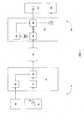
- FIG. 1 shows a block representation illustrating an embodiment of a first system coupled to a second system via a network according to the present invention.
- the first system 10 may include, for example, a command unit 20, a memory 30 having data 40 and a NIC 50.
- the NIC 50 may include, for example, a header processor 60, a data movement module 70 and a combiner 80.
- the first system 10 also may include other components and circuits which are not shown, but are well known to one skilled in the art.
- the command unit 20 is coupled to the header processor 60 which, in turn, is coupled to the combiner 80.
- the memory 30 is coupled to the data movement module 70 which, in turn, is coupled to the combiner 80.
- the combiner 80 is coupled to a network 90 (e.g., the Internet, an Ethernet, a local access network (LAN), a wide area network (WAN), a wireless network, etc.) Couplings between components may be achieved via a wired connection (e.g., wires, cables, etc.) or via a wireless connection.
- a network 90 e.g., the Internet, an Ethernet, a local access network (LAN), a wide area network (WAN), a wireless network, etc.
- Couplings between components may be achieved via a wired connection (e.g., wires, cables, etc.) or via a wireless connection.
- the second system 100 may include, for example, a NIC 110, a memory 120 and a system task monitor 130.
- the NIC 110 may include, for example, a header CRC unit 140, a header processor 150, a buffer 160, a data CRC unit 170, a data movement module 180 and a NIC task monitor 190.
- the network 90 is coupled to the NIC 110 via the buffer 160.
- the buffer 160 is coupled to the header CRC unit 140 which, in turn, is coupled to the header processor 150.
- the header processor 150 is coupled to the data movement module 180.
- the buffer 160 is also coupled to the data CRC unit 170 which, in turn, is coupled to the data movement module 180.
- the present invention may contemplate different degrees of integration between components.
- the CRC unit 140 and the CRC unit 170 can be integrated with the header processor 150 and the data movement module 180, respectively.
- the data movement module 180 is coupled to the NIC task monitor 190 which, in turn, is coupled to the system task monitor 130.
- the data movement module 180 is also coupled to the memory 120.
- the present invention may also contemplate other couplings other than or instead of those described herein.
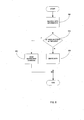
- FIGS. 3-5 show flowcharts illustrating embodiments of processes that may be used in transporting data from a first system to a second system according to the present invention.
- the command unit 20 in the first system 10 initiates a data transfer by providing the header processor 60 with a data transfer command and may provide an address (e.g., DDP information) to which the data can be transferred.
- the header processor 60 performs a CRC process and adds the CRC result to the header data stream.
- the data to be transferred is transported from the memory 30 to the data movement module 70 of the NIC 50.
- the data movement module 70 performs a CRC process and adds the CRC result to the data stream.
- the combiner 80 puts together the header information received from the header processor 60 (e.g., the address information, the header CRC, etc.) with the data information received from the data movement module 70 (e.g., the data, the data CRC, etc).
- the two data streams may be concatenated into a data packet 200 as illustrated in FIG. 2. In another embodiment, the two data streams may be concatenated in a different order than as illustrated in FIG. 2.
- each packet may be fully describing (e.g., self describing) such that the second system 100 (e.g., the NIC 110 of the second system 100) can process each packet independent of any other packet.
- the second system 100 e.g., the NIC 110 of the second system 100
- Some of the above-described steps may be performed in parallel.
- the CRC processes may be performed in parallel, thereby speeding up the process.
- the header processor 60 may work with the combiner 80 and the data movement module 70 in forming packets that may comply with, for example, any length restrictions imposed, for example, by the network 90.
- the header processor 60, the combiner 80 and the data movement module 70 may break up a requested data transfer into a plurality of data blocks so as to meet, for example, any network length restrictions.
- the header processor 60 may be adapted to provide a header and header CRC for each packet sent via the network 90.
- each header in each packet may independent and may fully describe its respective packet, which is part of a complete data transfer requested by the command unit 20.
- the data movement module 70 may break up data information into data blocks using a similar algorithm as the header processor 60. Accordingly, each data block may be associated (e.g., concatenated) with a respective independent header (e.g., a self-describing header).
- the data packet 200 is routed via the network 90 before being received by the second system 100 via, for example, the buffer 160 of the NIC 110.
- the buffer 160 may parse each received packet, thereby separating the control information (e.g., the header information) from the data information.
- header information is received by the header CRC unit 140.
- the header of the data packet 200 is checked for errors via a CRC algorithm in the header CRC unit 140. Subsequently, if there were no errors in the header, then, in step 280, the header processor 150 processes the header and determines a local memory address in memory 120 (e.g., host memory) which is forwarded to the data movement module 180.
- memory 120 e.g., host memory
- step 290 the data transfer process is terminated and a retransmit command is sent to the first system 10.
- the error may also be indicated to the system task monitor 130, which may facilitate a retransmission.
- Such an example of a transport process may have an advantage in that information is written in only the correct memory location of the memory 120 of the second system 100. Thus, critical systems may not be mistakenly overwritten if the local memory address is in error.
- the retransmit command is sent early in the process if the header has errors, the process may provide for less delay and faster transport rates.
- the dropping may be done before layer 4 (L4) transport process has been completed, the dropped data may be retransmitted using the mechanisms of L4 transport processing as opposed to using higher levels of protocol.
- L4 layer 4
- the processing of the data information may be conducted at least partially in parallel with the processing of the header information. Employing such a parallel architecture may provide, for example, efficiencies in time.
- step 300 data information is received by the data CRC unit 170.
- query 310 the data portion of the data packet 200 is checked for errors via a CRC algorithm in the data CRC unit 170. If the data CRC does not indicate an error, then, in step 320, the data movement module 180 takes the presumably correct local memory address information from the header processor 150 and the data from the data packet and writes the data at the prescribed local memory address of the memory 120.
- the NIC task monitor 190 may also notify the system task monitor 130 that the task is complete. If the data CRC indicates an error, then the NIC task monitor 190 may notify the system task monitor 130 that the task is not complete and may request that the data packet be retransmitted by the first system 10.
Landscapes
- Engineering & Computer Science (AREA)
- Computer Networks & Wireless Communication (AREA)
- Signal Processing (AREA)
- Computer Security & Cryptography (AREA)
- Theoretical Computer Science (AREA)
- Physics & Mathematics (AREA)
- Probability & Statistics with Applications (AREA)
- Computer Hardware Design (AREA)
- Computing Systems (AREA)
- General Engineering & Computer Science (AREA)
- Data Exchanges In Wide-Area Networks (AREA)
- Detection And Correction Of Errors (AREA)
- Detection And Prevention Of Errors In Transmission (AREA)
- Error Detection And Correction (AREA)
- Emergency Protection Circuit Devices (AREA)
Abstract
Description
Claims (27)
- A method for transmitting a data packet, comprising:creating a header CRC by performing a cyclic redundancy check (CRC) process on header information, the header information indicating where to place data information;separately creating a data CRC by performing the CRC process on the data information; andforming a data packet comprising the header information, the header CRC, the data information and the data CRC.
- The method according to claim 1, wherein the data packet is transmitted onto a network.
- The method according to claim 2, wherein the data packet complies with any length restrictions in the network.
- The method according to claim 1, wherein the header information, the header CRC, the data information and the data CRC are concatenated to form the data packet.
- The method according to claim 1, further comprising:receiving the transmitted data packet; andseparating control information from the data information of the data packet.
- The method according to claim 5, wherein the control information comprises header information.
- A method for processing a data packet, comprising:receiving a data packet, the data packet comprising header information and data information, the header information indicating where in a host memory to place the data information and being protected by a header CRC, the data information being protected by a data CRC; andseparating the header information from the data information of the data packet.
- The method according to claim 7, further comprising:processing the header information in parallel with the data information.
- The method according to claim 8, wherein the header information is processed separately from the data information.
- The method according to claim 7, further comprising:performing a CRC process on the header information; andif the CRC process on the header information indicates an error in the header information, then requesting a retransmission of the data packet.
- The method according to claim 7, further comprising:performing the CRC process on the data information; andif the CRC process on the data information indicates an error in the data information, then requesting a retransmission of the data packet.
- The method according to claim 11, wherein if the CRC process on the data information indicates the error in the data information, then the retransmission request is passed on to a control processor.
- The method according to claim 7, further comprising:performing a CRC process on the data information;performing the CRC process on the header information; andif both the CRC process on the data information and the CRC process on the header information indicate no error, then directly writing the data information at a memory location associated with a memory address based upon the header information.
- The method according to claim 7, further comprising:performing a CRC process on the header information to determine whether there is an error in the header information.
- A data packet, comprising:wherein the CRC data portion and the CRC header portion are separate.a data portion;a CRC data portion that is related to a performance of a CRC process on the data portion;a header portion comprising information relating to a memory location of a memory in which to place the data portion; anda CRC header portion that is related to the performance of the CRC process on the header portion,
- A system for protecting header information, comprising:wherein the command unit provides destination information to the NIC,a command unit;a memory; anda network interface card (NIC) coupled to the command unit and to the memory,
wherein the memory provides data information to the NIC,
wherein the NIC generates a header CRC by performing a CRC process on the destination information,
wherein the NIC generates a data CRC by performing the CRC process on the data information, and
wherein the NIC forms a data packet based upon at least the data information, the data CRC, the destination information and the header CRC. - The system according to claim 16, wherein the NIC comprises a header processor, a data movement module and a combiner, the combiner being coupled to the first header processor and to the first data movement module.
- The system according to claim 17, wherein the header processor performs the CRC process on the destination information.
- The system according to claim 17, wherein the data movement module performs the CRC process on the received data information.
- The system according to claim 17, wherein the combiner forms the data packet.
- The system according to claim 20, wherein the combiner concatenates the header information, the header CRC, the data information and the data CRC.
- A system that handles data packets, comprising:wherein the NIC receives a data packet,a NIC; anda memory coupled to the NIC,
wherein the NIC separates header information from data information of the data packet, and
wherein the header information indicates in which memory location of the memory to place the data information. - The system according to claim 22, wherein the NIC facilitates direct placement of data information into the memory.
- The system according to claim 22,
wherein NIC performs a CRC process on the header information to determine if the header information has a header error,
wherein the second network interface unit separately performs the CRC process on the data information to determine if the data information has a data error, and
wherein, if both the destination information and the data information are errorless, then NIC writes the data information directly to a memory location associated with a memory address, the memory address being a function of the header information. - The system according to claim 22, wherein the NIC comprises a buffer, a header processor and a data movement module.
- The system according to claim 22, wherein the NIC provides transmission control protocol (TCP) processing.
- The system according to claim 22, wherein the data packet is part of a byte stream.
Applications Claiming Priority (2)
| Application Number | Priority Date | Filing Date | Title |
|---|---|---|---|
| US36272902P | 2002-03-07 | 2002-03-07 | |
| US362729P | 2002-03-07 |
Publications (2)
| Publication Number | Publication Date |
|---|---|
| EP1345383A2 true EP1345383A2 (en) | 2003-09-17 |
| EP1345383A3 EP1345383A3 (en) | 2008-09-24 |
Family
ID=27766253
Family Applications (1)
| Application Number | Title | Priority Date | Filing Date |
|---|---|---|---|
| EP03005162A Ceased EP1345383A3 (en) | 2002-03-07 | 2003-03-07 | System and method for protecting header information using dedicated CRC |
Country Status (2)
| Country | Link |
|---|---|
| US (1) | US7055085B2 (en) |
| EP (1) | EP1345383A3 (en) |
Families Citing this family (23)
| Publication number | Priority date | Publication date | Assignee | Title |
|---|---|---|---|---|
| US7245613B1 (en) * | 2002-03-28 | 2007-07-17 | Advanced Micro Devices, Inc. | Arrangement in a channel adapter for validating headers concurrently during reception of a packet for minimal validation latency |
| US7747731B2 (en) * | 2003-03-27 | 2010-06-29 | Nokia Corporation | Minimizing message processing latency in a communication network |
| JP4196770B2 (en) * | 2003-07-23 | 2008-12-17 | ソニー株式会社 | Data processing method, data inspection method |
| US7219294B2 (en) * | 2003-11-14 | 2007-05-15 | Intel Corporation | Early CRC delivery for partial frame |
| US7143207B2 (en) * | 2003-11-14 | 2006-11-28 | Intel Corporation | Data accumulation between data path having redrive circuit and memory device |
| US7783769B2 (en) | 2004-03-31 | 2010-08-24 | Intel Corporation | Accelerated TCP (Transport Control Protocol) stack processing |
| US7055086B2 (en) * | 2004-04-06 | 2006-05-30 | Cisco Technology, Inc. | Method and apparatus for protecting parts of a packet in a wireless network |
| GB0408868D0 (en) * | 2004-04-21 | 2004-05-26 | Level 5 Networks Ltd | Checking data integrity |
| US20060168274A1 (en) * | 2004-11-08 | 2006-07-27 | Eliezer Aloni | Method and system for high availability when utilizing a multi-stream tunneled marker-based protocol data unit aligned protocol |
| GB0506403D0 (en) | 2005-03-30 | 2005-05-04 | Level 5 Networks Ltd | Routing tables |
| GB0505300D0 (en) | 2005-03-15 | 2005-04-20 | Level 5 Networks Ltd | Transmitting data |
| WO2006095184A2 (en) | 2005-03-10 | 2006-09-14 | Level 5 Networks Incorporated | Data processing system |
| GB0600417D0 (en) | 2006-01-10 | 2006-02-15 | Level 5 Networks Inc | Virtualisation support |
| US7710968B2 (en) * | 2006-05-11 | 2010-05-04 | Intel Corporation | Techniques to generate network protocol units |
| US8099521B2 (en) * | 2006-10-26 | 2012-01-17 | Interactic Holdings Inc. | Network interface card for use in parallel computing systems |
| US20090089475A1 (en) * | 2007-09-28 | 2009-04-02 | Nagabhushan Chitlur | Low latency interface between device driver and network interface card |
| JP4650516B2 (en) * | 2008-04-09 | 2011-03-16 | ソニー株式会社 | Imaging data management method and imaging apparatus |
| US9497095B2 (en) * | 2012-03-22 | 2016-11-15 | International Business Machines Corporation | Dynamic control over tracing of messages received by a message broker |
| US10146727B2 (en) | 2015-04-14 | 2018-12-04 | Qualcomm Incorporated | Enhanced virtual GPIO with multi-mode modulation |
| TWI698750B (en) * | 2018-03-20 | 2020-07-11 | 慧榮科技股份有限公司 | Method for accessing flash memory module and associated flash memory controller and electronic device |
| TWI658364B (en) | 2018-03-20 | 2019-05-01 | 慧榮科技股份有限公司 | Method for accessing flash memory module and associated flash memory controller and electronic device |
| FI129675B (en) * | 2020-02-11 | 2022-06-30 | Wirepas Oy | A solution for separating transmissions from different networks |
| CN114499750B (en) * | 2021-11-30 | 2025-05-02 | 华为技术有限公司 | A data packet processing method, communication device and communication system |
Family Cites Families (13)
| Publication number | Priority date | Publication date | Assignee | Title |
|---|---|---|---|---|
| US5579503A (en) * | 1993-11-16 | 1996-11-26 | Mitsubishi Electric Information Technology | Direct cache coupled network interface for low latency |
| US5933430A (en) * | 1995-08-12 | 1999-08-03 | Sony Corporation | Data communication method |
| EP0859324B1 (en) * | 1997-02-14 | 2007-01-03 | Canon Kabushiki Kaisha | Data transmission apparatus, system and method, and image processing apparatus |
| US6219697B1 (en) * | 1997-05-02 | 2001-04-17 | 3Com Corporation | Method and apparatus for operating the internet protocol over a high-speed serial bus |
| US6333929B1 (en) * | 1997-08-29 | 2001-12-25 | Intel Corporation | Packet format for a distributed system |
| US6009547A (en) * | 1997-12-03 | 1999-12-28 | International Business Machines Corporation | ECC in memory arrays having subsequent insertion of content |
| US6212633B1 (en) * | 1998-06-26 | 2001-04-03 | Vlsi Technology, Inc. | Secure data communication over a memory-mapped serial communications interface utilizing a distributed firewall |
| US6944763B1 (en) * | 1999-04-13 | 2005-09-13 | Sony Corporation | Data transmission system |
| JP3543698B2 (en) * | 1999-09-29 | 2004-07-14 | 日本電気株式会社 | Transmission method and network system |
| JP4192371B2 (en) * | 1999-12-09 | 2008-12-10 | ソニー株式会社 | Data receiving apparatus, data transmitting apparatus, and data transmitting / receiving system |
| JP4592935B2 (en) * | 2000-09-11 | 2010-12-08 | パナソニック株式会社 | Header restoration apparatus and header restoration method |
| US6845403B2 (en) * | 2001-10-31 | 2005-01-18 | Hewlett-Packard Development Company, L.P. | System and method for storage virtualization |
| US7155658B2 (en) * | 2002-12-20 | 2006-12-26 | Intel Corporation | CRC calculation for data with dynamic header |
-
2003
- 2003-03-04 US US10/378,803 patent/US7055085B2/en not_active Expired - Lifetime
- 2003-03-07 EP EP03005162A patent/EP1345383A3/en not_active Ceased
Non-Patent Citations (1)
| Title |
|---|
| SEONG L N ET AL: "Parallel realization of the ATM cell header CRC", 1 March 1996, COMPUTER COMMUNICATIONS, ELSEVIER SCIENCE PUBLISHERS BV, AMSTERDAM, NL, PAGE(S) 257 - 263, ISSN: 0140-3664, XP004032408 * |
Also Published As
| Publication number | Publication date |
|---|---|
| US20030169738A1 (en) | 2003-09-11 |
| US7055085B2 (en) | 2006-05-30 |
| EP1345383A3 (en) | 2008-09-24 |
Similar Documents
| Publication | Publication Date | Title |
|---|---|---|
| US7055085B2 (en) | System and method for protecting header information using dedicated CRC | |
| US11765079B2 (en) | Computational accelerator for storage operations | |
| US8958440B2 (en) | System and method for identifying upper layer protocol message boundaries | |
| US7904576B2 (en) | Reliable datagram via independent source destination resources | |
| US6683850B1 (en) | Method and apparatus for controlling the flow of data between servers | |
| US6343067B1 (en) | Method and apparatus for failure and recovery in a computer network | |
| US7734720B2 (en) | Apparatus and system for distributing block data on a private network without using TCP/IP | |
| US20050135395A1 (en) | Method and system for pre-pending layer 2 (L2) frame descriptors | |
| US6640325B1 (en) | Immediate negative acknowledgement for a communication network | |
| US6804804B2 (en) | Calculation and transmission of error check codes | |
| WO2000072159A1 (en) | Reliable datagram | |
| US8166127B2 (en) | Apparatus and methods for efficient insertion and removal of MPA markers and RDMA CRC digest | |
| US6996105B1 (en) | Method for processing data packet headers | |
| US20030076822A1 (en) | Data and context memory sharing | |
| EP1357721A2 (en) | System and method for identifying upper layer protocol message boundaries | |
| US7281052B2 (en) | Data tracing identifiers | |
| US8737431B2 (en) | Checking data integrity | |
| US7554917B1 (en) | TCP retransmission and exception processing in high speed, low memory hardware devices | |
| US20040174893A1 (en) | iSCSI apparatus and communication control method for the same | |
| US20050265352A1 (en) | Recovery from MSS change | |
| US7424544B2 (en) | Method for improving performance in computer networks based on lossy channel | |
| JP4400278B2 (en) | TCP processing circuit and semiconductor integrated circuit | |
| EP1734720B1 (en) | System and method for identifying upper layer protocol message boundaries |
Legal Events
| Date | Code | Title | Description |
|---|---|---|---|
| PUAI | Public reference made under article 153(3) epc to a published international application that has entered the european phase |
Free format text: ORIGINAL CODE: 0009012 |
|
| AK | Designated contracting states |
Kind code of ref document: A2 Designated state(s): AT BE BG CH CY CZ DE DK EE ES FI FR GB GR HU IE IT LI LU MC NL PT RO SE SI SK TR |
|
| AX | Request for extension of the european patent |
Extension state: AL LT LV MK |
|
| RAP1 | Party data changed (applicant data changed or rights of an application transferred) |
Owner name: BROADCOM CORPORATION |
|
| PUAL | Search report despatched |
Free format text: ORIGINAL CODE: 0009013 |
|
| AK | Designated contracting states |
Kind code of ref document: A3 Designated state(s): AT BE BG CH CY CZ DE DK EE ES FI FR GB GR HU IE IT LI LU MC NL PT RO SE SI SK TR |
|
| AX | Request for extension of the european patent |
Extension state: AL LT LV MK |
|
| 17P | Request for examination filed |
Effective date: 20090324 |
|
| AKX | Designation fees paid |
Designated state(s): DE FR GB |
|
| 17Q | First examination report despatched |
Effective date: 20090615 |
|
| APBK | Appeal reference recorded |
Free format text: ORIGINAL CODE: EPIDOSNREFNE |
|
| APBN | Date of receipt of notice of appeal recorded |
Free format text: ORIGINAL CODE: EPIDOSNNOA2E |
|
| APBR | Date of receipt of statement of grounds of appeal recorded |
Free format text: ORIGINAL CODE: EPIDOSNNOA3E |
|
| APAF | Appeal reference modified |
Free format text: ORIGINAL CODE: EPIDOSCREFNE |
|
| APAF | Appeal reference modified |
Free format text: ORIGINAL CODE: EPIDOSCREFNE |
|
| APBT | Appeal procedure closed |
Free format text: ORIGINAL CODE: EPIDOSNNOA9E |
|
| STAA | Information on the status of an ep patent application or granted ep patent |
Free format text: STATUS: THE APPLICATION HAS BEEN REFUSED |
|
| 18R | Application refused |
Effective date: 20160530 |