EP1345104B1 - Control system for an electric heater - Google Patents
Control system for an electric heater Download PDFInfo
- Publication number
- EP1345104B1 EP1345104B1 EP03075578A EP03075578A EP1345104B1 EP 1345104 B1 EP1345104 B1 EP 1345104B1 EP 03075578 A EP03075578 A EP 03075578A EP 03075578 A EP03075578 A EP 03075578A EP 1345104 B1 EP1345104 B1 EP 1345104B1
- Authority
- EP
- European Patent Office
- Prior art keywords
- heating element
- control
- current
- voltage
- heating
- Prior art date
- Legal status (The legal status is an assumption and is not a legal conclusion. Google has not performed a legal analysis and makes no representation as to the accuracy of the status listed.)
- Expired - Lifetime
Links
- 238000010438 heat treatment Methods 0.000 claims description 92
- 239000000446 fuel Substances 0.000 claims description 41
- 239000003054 catalyst Substances 0.000 claims description 9
- 230000001939 inductive effect Effects 0.000 claims description 9
- 238000012544 monitoring process Methods 0.000 claims description 8
- 239000007787 solid Substances 0.000 claims description 6
- 230000000063 preceeding effect Effects 0.000 claims 1
- 238000010586 diagram Methods 0.000 description 8
- 230000007704 transition Effects 0.000 description 8
- 239000007789 gas Substances 0.000 description 6
- 238000005259 measurement Methods 0.000 description 6
- 238000000034 method Methods 0.000 description 6
- 238000012546 transfer Methods 0.000 description 6
- 230000008569 process Effects 0.000 description 5
- 239000003990 capacitor Substances 0.000 description 4
- 230000003197 catalytic effect Effects 0.000 description 4
- 239000001257 hydrogen Substances 0.000 description 4
- 229910052739 hydrogen Inorganic materials 0.000 description 4
- 238000004364 calculation method Methods 0.000 description 3
- 238000002485 combustion reaction Methods 0.000 description 3
- 239000002737 fuel gas Substances 0.000 description 3
- 230000006870 function Effects 0.000 description 3
- 239000001301 oxygen Substances 0.000 description 3
- 229910052760 oxygen Inorganic materials 0.000 description 3
- IJGRMHOSHXDMSA-UHFFFAOYSA-N Atomic nitrogen Chemical compound N#N IJGRMHOSHXDMSA-UHFFFAOYSA-N 0.000 description 2
- 239000004215 Carbon black (E152) Substances 0.000 description 2
- UGFAIRIUMAVXCW-UHFFFAOYSA-N Carbon monoxide Chemical compound [O+]#[C-] UGFAIRIUMAVXCW-UHFFFAOYSA-N 0.000 description 2
- UFHFLCQGNIYNRP-UHFFFAOYSA-N Hydrogen Chemical compound [H][H] UFHFLCQGNIYNRP-UHFFFAOYSA-N 0.000 description 2
- QVGXLLKOCUKJST-UHFFFAOYSA-N atomic oxygen Chemical compound [O] QVGXLLKOCUKJST-UHFFFAOYSA-N 0.000 description 2
- 229910002091 carbon monoxide Inorganic materials 0.000 description 2
- 238000006243 chemical reaction Methods 0.000 description 2
- 230000000694 effects Effects 0.000 description 2
- 239000003502 gasoline Substances 0.000 description 2
- 229930195733 hydrocarbon Natural products 0.000 description 2
- 150000002430 hydrocarbons Chemical class 0.000 description 2
- 150000002431 hydrogen Chemical class 0.000 description 2
- 238000002407 reforming Methods 0.000 description 2
- BVKZGUZCCUSVTD-UHFFFAOYSA-L Carbonate Chemical compound [O-]C([O-])=O BVKZGUZCCUSVTD-UHFFFAOYSA-L 0.000 description 1
- 230000009471 action Effects 0.000 description 1
- 238000004378 air conditioning Methods 0.000 description 1
- 230000008901 benefit Effects 0.000 description 1
- 239000000919 ceramic Substances 0.000 description 1
- 238000001816 cooling Methods 0.000 description 1
- 238000005485 electric heating Methods 0.000 description 1
- 230000005611 electricity Effects 0.000 description 1
- 239000003792 electrolyte Substances 0.000 description 1
- 230000005669 field effect Effects 0.000 description 1
- 238000000691 measurement method Methods 0.000 description 1
- 239000002905 metal composite material Substances 0.000 description 1
- 239000000203 mixture Substances 0.000 description 1
- 238000012986 modification Methods 0.000 description 1
- 230000004048 modification Effects 0.000 description 1
- 229910052757 nitrogen Inorganic materials 0.000 description 1
- 238000013021 overheating Methods 0.000 description 1
- 230000003647 oxidation Effects 0.000 description 1
- 238000007254 oxidation reaction Methods 0.000 description 1
- -1 oxygen ion Chemical class 0.000 description 1
- 238000010926 purge Methods 0.000 description 1
- 238000011084 recovery Methods 0.000 description 1
- 238000005057 refrigeration Methods 0.000 description 1
- 102220213553 rs1026192345 Human genes 0.000 description 1
- 238000005070 sampling Methods 0.000 description 1
- 230000003068 static effect Effects 0.000 description 1
- 230000001360 synchronised effect Effects 0.000 description 1
- 239000002699 waste material Substances 0.000 description 1
- XLYOFNOQVPJJNP-UHFFFAOYSA-N water Substances O XLYOFNOQVPJJNP-UHFFFAOYSA-N 0.000 description 1
Images



Classifications
-
- G—PHYSICS
- G05—CONTROLLING; REGULATING
- G05D—SYSTEMS FOR CONTROLLING OR REGULATING NON-ELECTRIC VARIABLES
- G05D23/00—Control of temperature
- G05D23/19—Control of temperature characterised by the use of electric means
- G05D23/20—Control of temperature characterised by the use of electric means with sensing elements having variation of electric or magnetic properties with change of temperature
- G05D23/24—Control of temperature characterised by the use of electric means with sensing elements having variation of electric or magnetic properties with change of temperature the sensing element having a resistance varying with temperature, e.g. a thermistor
- G05D23/2401—Control of temperature characterised by the use of electric means with sensing elements having variation of electric or magnetic properties with change of temperature the sensing element having a resistance varying with temperature, e.g. a thermistor using a heating element as a sensing element
-
- H—ELECTRICITY
- H01—ELECTRIC ELEMENTS
- H01M—PROCESSES OR MEANS, e.g. BATTERIES, FOR THE DIRECT CONVERSION OF CHEMICAL ENERGY INTO ELECTRICAL ENERGY
- H01M8/00—Fuel cells; Manufacture thereof
- H01M8/10—Fuel cells with solid electrolytes
- H01M8/12—Fuel cells with solid electrolytes operating at high temperature, e.g. with stabilised ZrO2 electrolyte
- H01M2008/1293—Fuel cells with solid oxide electrolytes
-
- H—ELECTRICITY
- H01—ELECTRIC ELEMENTS
- H01M—PROCESSES OR MEANS, e.g. BATTERIES, FOR THE DIRECT CONVERSION OF CHEMICAL ENERGY INTO ELECTRICAL ENERGY
- H01M8/00—Fuel cells; Manufacture thereof
- H01M8/06—Combination of fuel cells with means for production of reactants or for treatment of residues
- H01M8/0606—Combination of fuel cells with means for production of reactants or for treatment of residues with means for production of gaseous reactants
- H01M8/0612—Combination of fuel cells with means for production of reactants or for treatment of residues with means for production of gaseous reactants from carbon-containing material
-
- Y—GENERAL TAGGING OF NEW TECHNOLOGICAL DEVELOPMENTS; GENERAL TAGGING OF CROSS-SECTIONAL TECHNOLOGIES SPANNING OVER SEVERAL SECTIONS OF THE IPC; TECHNICAL SUBJECTS COVERED BY FORMER USPC CROSS-REFERENCE ART COLLECTIONS [XRACs] AND DIGESTS
- Y02—TECHNOLOGIES OR APPLICATIONS FOR MITIGATION OR ADAPTATION AGAINST CLIMATE CHANGE
- Y02E—REDUCTION OF GREENHOUSE GAS [GHG] EMISSIONS, RELATED TO ENERGY GENERATION, TRANSMISSION OR DISTRIBUTION
- Y02E60/00—Enabling technologies; Technologies with a potential or indirect contribution to GHG emissions mitigation
- Y02E60/30—Hydrogen technology
- Y02E60/50—Fuel cells
Definitions
- the present invention is generally directed to a control system, and, more specifically, to a control system for an electric heater.
- Electric catalyst heaters have been proposed for use in a variety of applications, such as a micro-reformer, a main fuel reformer, electrically heated catalytic converters and in other applications that implement a low impedance heating element that requires temperature control such as furnaces and ovens.
- an ECH When implemented within a micro-reformer, an ECH is used to warm a reformer catalyst to initiate the reforming process.
- the fuel reforming process produces hydrogen, which can be used for fuel in a fuel cell or to help internal combustion engines (ICEs) meet super ultra low emission vehicle (SULEV) emission requirements.
- SULEV super ultra low emission vehicle
- an ECH typically also allows for reduced emissions due to light off (i.e., heating to a temperature where catalytic activity begins).
- an ECH When implemented within a fuel reformer, a typical ECH element needs to be maintained at a temperature that corresponds to a very narrow resistance range.
- an ECH may exhibit a resistance of thirty-five milliohms at 25°C and forty-one milliohms at 525°C.
- a heating element may exhibit a resistance between twenty-five and one-hundred milliohms.
- Traditional resistance measurement techniques which have involved using a bridge and a series measurement element, are generally ineffective at such low resistance levels. This is due to the fact that the series element must generally have a resistance much less than forty milliohms, a high power rating and allow for precise measurement with high accuracy. This combination of requirements is generally difficult and expensive to meet when attempting such resistance measurements with a bridge that uses a series measurement element.
- US Patent No. 4,162,379 describes a system in which power is applied to an electrical element in maintaining a thermal system at stabilized conditions and a feedback signal is derived to control the electrical input to the heating element by linearly combining functions of the current through the heating element and the voltage drop thereacross respectively.
- US Patent No. 3,718,506 describes a fuel cell system of the high temperature type which includes one or more fuel cells operating with an electrolyte such as an oxygen ion conductive solid or a carbonate melt to which fresh reaction gases containing hydrocarbon fuel and oxygen respectively are fed after preheating in heat exchangers.
- an electrolyte such as an oxygen ion conductive solid or a carbonate melt to which fresh reaction gases containing hydrocarbon fuel and oxygen respectively are fed after preheating in heat exchangers.
- a portion of the exhaust gases from the fuel side of the cell is recycled through the fuel cell by entrainment with fresh fuel gas by means of the aspirating effect of a nozzle through which fresh fuel gas is injected into the cell and the remainder of the exhaust gas from the fuel side together with oxygen impoverished gas discharged from the cell are led to an after-combustion catalyst in the form of a tubular structure surrounding the fuel cells and also the reformer component if one is utilized for burning of the remaining hydrocarbon content of the fuel gas.
- the heat generated during the after-burning phase in the catalytic zone is mostly transferred over a very short path to the fuel cells to maintain the fuel cells at their proper operating temperature and to supply the power requirements of the reformer if the latter is utilized.
- the remaining heat in the exhaust gases is conducted to the exchangers for heat transfer to the incoming fresh reaction gases.
- An embodiment of the present invention is directed to a control system for an electric heater, e.g., an electric catalyst heater (ECH), that includes a current sensor, a voltage sensor, a switching element, and a control circuit.
- the current sensor is positioned to sense a heating current through a heating element and the voltage sensor is positioned across the heating element to sense a heating voltage.
- the switching element includes a control terminal and is coupled between the heating element and a power supply to interrupt the heating current, through the heating element, responsive to a control signal on the control terminal.
- the control circuit is coupled to the current sensor, the voltage sensor and the control terminal of the switching element and varies the control signal to maintain the temperature of the heating element within a predetermined temperature range.
- the current sensor is a non-contact inductive current sensor.
- the control circuit includes a microcontroller.
- a temperature sensor is not required to monitor the temperature of the heating element and the heating element can be monitored without adding a costly high power series element, which, when implemented, produces additional heat.
- the microcontroller is programmed to prevent overheating and subsequent damage of the heating element.
- a control system can be utilized with a heating element that requires rapid warm-up for use in various applications, such as micro-reformers for solid oxide fuel cells (SOFCs).
- a control system for an electric heater comprising; a current sensor positioned to sense a heating current through a heating element (HE) of an electric heater wherein the current sensor is a non-contact inductive sensor; a voltage sensor positioned across the heating element (HE) to sense a heating voltage; a switching element including a control terminal, wherein the switching element is coupled between the heating element (HE) and a power supply (VDC) to interrupt the heating current through the heating element (HE) respective to a control signal on the control terminal; and a control circuit coupled to the current sensor, the voltage sensor and the control terminal of the switching element, wherein the control circuit varies the control signal to maintain a temperature of the heating element (HE) within a predetermined temperature range; characterised in that both the current sensor sensing the heating current and the voltage sensor sensing the heating voltage operate at a regular fixed real-time interval, said real-time interval differing from a reference signal period of the control circuit.
- the current sensor includes a low-pass filter.
- control circuit is a microcontroller.
- the voltage sensor includes a differential amplifier whose imputs are coupled across the heating element (HE).
- HE heating element
- a resistance of the heating element (HE) is in range of about twenty-five to one-hundred milliohms when the temperature of the heating element (HE) is within the predetermined temperature range.
- control circuit maintains the temperature of the heating element (HE) within the predetermined temperature range by periodically varying at least one of a pulse width and a frequency of the control signal to maintain a substantially constant heater resistance as calculated from the heater current provided by the current sensor and the heater voltage provided by the voltage sensor.
- the electric heater is an electric catalyst heater (ECH).
- EH electric catalyst heater
- an auxiliary power unit comprising; a fuel reformer, including an electric heater (HE); and a control system for monitoring a temperature of the electric heater (HE) as provided by the first aspect; and a solid oxide fuel cell receiving reformate from the fuel reformer.
- an automotive control system for an electric catalyst heater comprising a control system as provided by the first aspect of the invention.
- the present invention is generally directed to a control system for an electric heater, e.g., an electric catalyst heater (ECH), that includes a current sensor, a voltage sensor, a switching element, and a control circuit.
- the current sensor is positioned to sense a heating current through a heating element and the voltage sensor is positioned across the heating element to sense a heating voltage. It should be appreciated that the voltage sensor may be positioned directly or indirectly (i.e., across the heating element and additional components) across the heating element.
- the switching element includes a control terminal and is coupled between the heating element and a power supply to interrupt the heating current, through the heating element, responsive to a control signal on the control terminal.
- the control circuit is coupled to the current sensor, the voltage sensor and the control terminal of the switching element and varies the timing of the control signal to maintain the temperature of the heating element within a predetermined temperature range.
- an APU with a fuel reformer may provide power to operate various automotive accessories, e.g., heated seats, a heated windshield, power steering, power brakes, electric air conditioning, electromagnetic valve train systems, electric water pumps, navigation systems, sound systems, vehicle heating systems, telecommunication systems and may be used to run refrigeration units in commercial vehicles.
- the hydrogen produced by the fuel reformer can also be mixed with vehicle fuel for more efficient combustion with reduced emissions.
- Another application is an electric heater useful in providing heat to automotive passenger compartments for vehicles having ICEs with low heat rejection or having no ICE, such as an electric vehicle.
- Electrically heated windshields are also low-impedance heating elements that can benefit from temperature control to limit heating effects, depending on the thermal load (e.g., an iced windshield versus light snow). Additional applications include electric heating elements for furnaces and ovens.
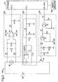
- Fig. 1 depicts an electrical block diagram of a control system 100 that monitors and controls the temperature of a heating element HE that receives power from a power supply VDC, which may be a battery, a series of batteries, a generator, a fuel cell a DC-to-DC converter or other direct current electrical source.
- the control system 100 monitors the current through and the voltage across the heating element HE, provided by the power supply VDC, and modifies a control signal to maintain a required heating element HE temperature.
- Inputs of a voltage sensor 106 are coupled across the heating element HE and an output of the circuit 106 is coupled to an input HTR_V of a processor 102.
- a current sensor 108 senses the current through the heating element HE and provides an output signal to an input HTR_I of the processor 102.
- the current sensor 108 includes an inductive current sensor 112 that is coupled to a filter network 114.
- a control signal is provided by the processor 102 on an output EHC_DRIVE, which is coupled to a drive circuit 118 that is, in turn, coupled to a gate of a field effect transistor (FET) 116 that is part of a switching circuit 110.
- FET field effect transistor
- the FET 116 may be replaces with a high-current switching means, such as an isolated gate bipolar transistor (IGBT), bipolar junction transistor (BJT), or the like.
- the processor 102 is also coupled to a memory subsystem 104, which may include an application appropriate amount of volatile (e.g., static random access memory (SRAM)) and non-volatile memory (e.g., electrically erasable programmable read-only memory (EEPROM)).
- a memory subsystem 104 may include an application appropriate amount of volatile (e.g., static random access memory (SRAM)) and non-volatile memory (e.g., electrically erasable programmable read-only memory (EEPROM)).
- the processor 102 and the memory subsystem 104 may be incorporated within a microcontroller 120 or, in general, the functions associated with the processor 102 may be implemented by a control circuit.
- Elements 106, 114 and 118 can also be implemented within one or more integrated circuits.
- Fig. 2 depicts an electrical diagram in block and schematic form of an exemplary control system 100A and further details an exemplary voltage sensor 106A, an exemplary current sensor 108A and an exemplary drive circuit 118A.
- the EHC_DRIVE output of the processor 102 is utilized to turn on/off the FET 116, when appropriate.
- a high level signal on the EHC_DRIVE output turns on NPN transistor Q2, which, in turn, turns on PNP transistor Q1, when an external power supply +SW_PWR is active.
- the transistor Q2 along with associated resistors R1 and R2 (e.g., 1kohm and 430ohm, respectively), invert the signal provided by the processor 102 on the EHC_DRIVE output. For example, when a five volt signal is provided on the EHC_DRIVE output, the transistor Q2 is turned on.
- a resistor R3 limits a base current of the transistor Q1 and a resistor R4 (e.g., 2.2kohm) is coupled between an emitter and a base of the transistor Q1 and ensures that transistor Q1 stays off when transistor Q2 is off. Resistors R3 and R4 also provide the collector current for transistor Q2.
- a collector of the transistor Q1 is coupled, via a resistor R5 (e.g., 20ohm), to the gate of the FET 116.
- a cathode of zener diode D1 is coupled to the gate of the FET 116 and an anode of the zener diode D1 is coupled to an anode of zener diode D2.
- a cathode of the zener diode D2 is coupled to a common ground.
- a resistor R6 (e.g., 510ohm) is coupled between the gate of the FET 116 and the common ground.
- the diodes D1 and D2 serve to protect the gate of the FET 116 from negative and positive going transients.
- the resistor R6 pulls the gate of the FET 116 to the common ground when the transistor Q1 is turned off.
- a positive voltage is provided at the collector of the transistor Q1, which provides a turn on signal to the gate of the FET 116, through the resistor R5.
- a source of the FET 116 is coupled to a negative terminal of the power supply VDC and a drain of the FET 116 is coupled to one side of the heating element HE.
- a second side of the heating element HE is coupled to a positive terminal of the power supply VDC.
- An output of an inductive current sensor 112 is coupled to an input HTR_I of the processor 102, via a filter network 114A.
- the output of the inductive current sensor 112 is filtered by the filter network 114A, which includes resistors R8 and R7 and a capacitor C1 (e.g., 220kohm, 1kohm and 0.033uF, respectively), which provide, for example, a time constant of thirty microseconds.
- the output of the inductive current sensor 112 is low-pass filtered before being provided to the HTR_I input of the processor 102.
- the operational amplifier Q3 is differentially coupled across the heating element HE via a resistive divider network incorporating resistors R9, R10 and R11 (e.g., 1kohm, 1kohm and 1kohm, respectively).
- a capacitor C2 e.g., 0.033uF
- An output of the amplifier Q3 is coupled through a low-pass filter, including resistor R12 and a capacitor C3 (e.g., 400ohm and 0.15uF, respectively) to the HTR_V input of the processor 102, which sets a time constant of approximately sixty microseconds.
- the time constant can be increased such that the voltage is averaged by the resistor R12 and the capacitor C3.
- the processor 102 can periodically determine the voltage present at the HTR_V input and a current present at an HTR_I input and selectively provide a signal on the EHC_DRIVE output to control the temperature of the heating element HE within a predetermined temperature range.
- the current signal HTR_I depicts an exemplary current passing through the heating element HE, as provided by the inductive current sensor 112 and the filter network 114A.
- the voltage signal HTR_V depicts an exemplary voltage across the heating element HE.
- the processor 102 periodically samples 302 the current HTR_I and the voltage HTR_V and calculates the resistance of the heating element HE, while the FET 116 is conducting, as is shown by the signal labeled "Heating Pulse.” Based upon the current and voltage sensed, the processor 102 may lengthen or shorten the width of a pulse provided on the EHC_DRIVE output to maintain the temperature of the heating element HE within a predetermined temperature range.
- the processor 102 is programmed with a lower fault limit (R_low_fault) and an upper fault limit (R_high_fault), as well as a target resistance.
- the resistance of a resistive heating element varies in proportion to the temperature of the heating element, it is possible to estimate and control the temperature of the element by measuring and controlling the resistance of the element.
- measurement of a low resistance series element is generally difficult due to the low resistance of the heating element HE.
- the low resistance of the heating element HE makes it generally impractical to use an element in series with the heating element HE to determine the current through the heating element HE. This is because a series device would generally introduce a relatively large voltage drop and require a higher power device, since the product of the current, which can be as large as three-hundred amperes, and the voltage is relatively high. High power devices are often bulky, expensive and also reduce the power that can be transferred to the heating element HE and, as such, are generally inefficient.
- the current through heating element HE is measured by a non-contact inductive current sensor.
- the output of the current sensor is passed through a simple filter (e.g., a RC) network with a time constant of approximately thirty microseconds.
- the time constant may be increased such that the current is averaged by the filter network 114A.
- the processor 102 implements a control and monitoring algorithm that switches the FET 116 on at a regular interval TPERIOD, which can be varied from interval to interval, if desired. Varying the interval TPERIOD may be particularly desirable during warm-up and cool-down phases.
- the processor 102 implements a real-time execution scheme in which it performs a schedule of operations (e.g., measures the current through and the voltage across the heating element HE and calculates a corresponding resistance) at a regular fixed real-time interval TREAL, shown in Fig. 3. It is generally desirable that TPERIOD be significantly larger than TREAL to allow for adequate control resolution. In one embodiment, TPERIOD is at least one-hundred times larger than TREAL.
- Fig. 4 depicts a simplified state diagram of an exemplary sequential state machine, which can, for example, be implemented as a monitoring control routine on the processor 102.
- state S1 the ERC_DRIVE output of the processor 102 is set to a low level.
- state S2 i.e., S12
- loops on state S1 i.e., S11
- the counter ctr
- the next state is the present state, i.e., state S1.
- the processor 102 provides a high signal on the EHC_DRIVE output, performs a resistance calculation (Resistance_start) and initializes a current and voltage variable (Curr_start and V_start, respectively).
- the machine then transitions from the present state S2 to a next state S3 (along the path S23) when the counter (ctr) is less than the time period Local_on_time.
- the next state is state S1. As is further discussed herein, this is utilized to initiate a "monitoring pulse" (see Fig. 3).
- the processor 102 measures the voltage across the heating element HE and the current through the heating element HE to perform a number of instantaneous resistance calculations, while the instantaneous resistance (R_instant) is less than or equal to a high fault threshold (R_highfault), greater than or equal to a low fault threshold (R_lowfault) or less than a target resistance (Target_R), or the counter (ctr) is less than the local on-time (Local_on_time).
- R_instant instantaneous resistance
- R_highfault high fault threshold
- R_lowfault low fault threshold
- Tiget_R target resistance
- the counter ctr
- the machine transitions from the present state S4, along the path S41, to the next state S1.
- state S3 when the counter (ctr) is greater than or equal to the local on-time, the machine transitions from the state S3, along path S31B, to the next state S 1 and a truncate variable (truncate) is set to zero indicating a normal termination of the EHC_DRIVE pulse and a time remaining variable (T_remain) is set to zero.
- state S3 when the instantaneous resistance is greater than or equal to the target resistance, the state transitions along the path state S31A and the truncate variable is set to a value of one (indicating the variable Local_on_time was too long) and the time remaining variable (T_remain) is set equal to the Local_on_time variable minus the counter (ctr).
- the processor 102 performs a resistance calculation during each real-time loop (TREAL), while the FET 116 is on.
- the FET 116 is turned off if any one of the following conditions occurs: an instantaneous resistance (R_instant) of the heating element HE is greater than a target resistance (R_target), the instantaneous resistance of the heating element HE is greater than a high resistance fault (R_highfault), the instantaneous resistance of the heating element HE is less than a low resistance fault (R_lowfault) or switch on-time (as tracked by a counter (ctr)) is greater than or equal to an on-time limit (Local_on_time), which is calculated from the limit of the pulse duty cycle.
- an external enable function allows a separate logic input to disable the switching action.
- a synchronous sampling technique is used to monitor the resistance (i.e., the temperature) of the heater element HE without imparting significant energy to the element. As is shown in Fig. 3, monitoring is preferably achieved by setting TPERIOD to a large value (e.g., three seconds) while setting a duty cycle limit to zero.
- TPERIOD a large value (e.g., three seconds) while setting a duty cycle limit to zero.
- step 502 An exemplary control and monitoring routine 500 for monitoring and controlling a heating element HE is set forth in Fig. 5.
- the routine 500 is initiated at which point control transfers to step 504 where various variables, discussed above, are initialized.
- step 506 the processor 102, implementing routine 500, selects an appropriate time period (TPERIOD).
- step 508 the processor 102 causes the FET 116 to be switched on.
- step 510 the processor 102 samples the current and voltage at appropriate intervals (i.e., TREAL) at the HTR_I and the HTR_V inputs of the processor 102.
- TREAL appropriate intervals
- step 512 the processor 102 calculates the resistance.
- decision step 514 the processor 102 determines whether an off condition is true.
- the FET 116 is preferably turned off when the instantaneous resistance is greater than the target resistance, greater than a high fault resistance, less than a low fault resistance or when the switch on-time exceeds an on-time limit. While all of the off conditions are false, control transfers from step 514 to step 510. If an off condition is true in step 514, control transitions to step 516 where the FET 116 is turned off.
- decision step 518 the processor 102 determines whether the TPERIOD has expired. If so, control transfers to step 520. Otherwise, control loops on step 518. In step 520, the processor 102 adjusts TPERIOD if required before transitioning to step 508.
- Fig. 6 depicts various subsystems of a solid oxide fuel cell (SOFC) auxiliary power unit (APU).
- the SOFC 602 includes a fuel reformer 604 that receives air from a process air supply subsystem 612 and fuel from an external fuel source.
- the fuel reformer 604 includes a heating element HE that is monitored by a control system, according to an embodiment of the present invention, as previously described herein.
- the control system may, for example, be incorporated with a system controller block 614.
- a typical fuel reformer includes a micro-reformer for starting the system and heating the main reformer and a main reformer for fueling the system once the fuel reformer is initiated.
- a typical APU uses a partial oxidation reformer that utilizes gasoline and air to catalytically convert the gasoline and air, primarily to hydrogen, carbon monoxide and nitrogen.
- the fuel reformer 604 is housed inside a hot box 602 and operates at a high temperature (e.g., 650-800 degrees C).
- a typical fuel reformer is fed fuel and air through valves located in a main plenum chamber. The fuel is introduced through insulated walls by way of an injector and the output of the reformer 604, which generally includes a hydrogen and carbon monoxide fuel mixture, is fed to the SOFC stack 606.
- a typical SOFC stack includes a multilayer ceramic/metal composite structure, which is designed to produce electricity at operating temperatures around 650-850 degrees C.
- a waste energy recovery subsystem 608 serves to convert unused reformate fuel and thermal energy, output from the stack 606, to input thermal energy for the fuel reformer 604.
- a typical process air subsystem 612 includes an electrical powered blower fan that pressurizes each chamber for process air cooling and purging of the SOFC system.
- the SOFC APU system 600 provides auxiliary electrical power for automotive accessories normally with higher efficiency than conventional systems and can do so during extended engine off periods.
- a typical system 600 provides power at about five kilowatts and approximately forty-two volts.
- a control system that monitors and controls the temperature of a heating element HE without substantially affecting the current through or the voltage across a heating element.
- Such a control system is particularly advantageous when utilized to control a heating element HE of a micro-reformer implemented within an automotive APU.
Landscapes
- Physics & Mathematics (AREA)
- General Physics & Mathematics (AREA)
- Engineering & Computer Science (AREA)
- Automation & Control Theory (AREA)
- Fuel Cell (AREA)
- Hydrogen, Water And Hydrids (AREA)
Description
- The present invention is generally directed to a control system, and, more specifically, to a control system for an electric heater.
- Electric catalyst heaters (ECHs) have been proposed for use in a variety of applications, such as a micro-reformer, a main fuel reformer, electrically heated catalytic converters and in other applications that implement a low impedance heating element that requires temperature control such as furnaces and ovens. When implemented within a micro-reformer, an ECH is used to warm a reformer catalyst to initiate the reforming process. The fuel reforming process produces hydrogen, which can be used for fuel in a fuel cell or to help internal combustion engines (ICEs) meet super ultra low emission vehicle (SULEV) emission requirements. When implemented within a catalytic converter, an ECH typically also allows for reduced emissions due to light off (i.e., heating to a temperature where catalytic activity begins).
- When implemented within a fuel reformer, a typical ECH element needs to be maintained at a temperature that corresponds to a very narrow resistance range. For example, an ECH may exhibit a resistance of thirty-five milliohms at 25°C and forty-one milliohms at 525°C. As another example, a heating element may exhibit a resistance between twenty-five and one-hundred milliohms. Traditional resistance measurement techniques, which have involved using a bridge and a series measurement element, are generally ineffective at such low resistance levels. This is due to the fact that the series element must generally have a resistance much less than forty milliohms, a high power rating and allow for precise measurement with high accuracy. This combination of requirements is generally difficult and expensive to meet when attempting such resistance measurements with a bridge that uses a series measurement element.
- US Patent No. 4,162,379 describes a system in which power is applied to an electrical element in maintaining a thermal system at stabilized conditions and a feedback signal is derived to control the electrical input to the heating element by linearly combining functions of the current through the heating element and the voltage drop thereacross respectively.
- US Patent No. 3,718,506 describes a fuel cell system of the high temperature type which includes one or more fuel cells operating with an electrolyte such as an oxygen ion conductive solid or a carbonate melt to which fresh reaction gases containing hydrocarbon fuel and oxygen respectively are fed after preheating in heat exchangers. A portion of the exhaust gases from the fuel side of the cell is recycled through the fuel cell by entrainment with fresh fuel gas by means of the aspirating effect of a nozzle through which fresh fuel gas is injected into the cell and the remainder of the exhaust gas from the fuel side together with oxygen impoverished gas discharged from the cell are led to an after-combustion catalyst in the form of a tubular structure surrounding the fuel cells and also the reformer component if one is utilized for burning of the remaining hydrocarbon content of the fuel gas. The heat generated during the after-burning phase in the catalytic zone is mostly transferred over a very short path to the fuel cells to maintain the fuel cells at their proper operating temperature and to supply the power requirements of the reformer if the latter is utilized. The remaining heat in the exhaust gases is conducted to the exchangers for heat transfer to the incoming fresh reaction gases.
- What is needed is a control system that performs temperature control of a low impedance series element that is practical, economical and relatively accurate.
- An embodiment of the present invention is directed to a control system for an electric heater, e.g., an electric catalyst heater (ECH), that includes a current sensor, a voltage sensor, a switching element, and a control circuit. The current sensor is positioned to sense a heating current through a heating element and the voltage sensor is positioned across the heating element to sense a heating voltage. The switching element includes a control terminal and is coupled between the heating element and a power supply to interrupt the heating current, through the heating element, responsive to a control signal on the control terminal. The control circuit is coupled to the current sensor, the voltage sensor and the control terminal of the switching element and varies the control signal to maintain the temperature of the heating element within a predetermined temperature range.
- According to one embodiment of the present invention, the current sensor is a non-contact inductive current sensor. According to another embodiment of the present invention, the control circuit includes a microcontroller. According to the present invention, a temperature sensor is not required to monitor the temperature of the heating element and the heating element can be monitored without adding a costly high power series element, which, when implemented, produces additional heat. Further, when a microcontroller is utilized, high accuracy can be achieved through high-speed measurements. In one embodiment, the microcontroller is programmed to prevent overheating and subsequent damage of the heating element. A control system, according to the present invention, can be utilized with a heating element that requires rapid warm-up for use in various applications, such as micro-reformers for solid oxide fuel cells (SOFCs).
- According to the first aspect of the invention there is provided a control system for an electric heater, comprising;
a current sensor positioned to sense a heating current through a heating element (HE) of an electric heater wherein the current sensor is a non-contact inductive sensor;
a voltage sensor positioned across the heating element (HE) to sense a heating voltage;
a switching element including a control terminal, wherein the switching element is coupled between the heating element (HE) and a power supply (VDC) to interrupt the heating current through the heating element (HE) respective to a control signal on the control terminal; and
a control circuit coupled to the current sensor, the voltage sensor and the control terminal of the switching element, wherein the control circuit varies the control signal to maintain a temperature of the heating element (HE) within a predetermined temperature range;
characterised in that both the current sensor sensing the heating current and the voltage sensor sensing the heating voltage operate at a regular fixed real-time interval, said real-time interval differing from a reference signal period of the control circuit. - Preferably, the current sensor includes a low-pass filter.
- Preferably, the control circuit is a microcontroller.
- Desirably, the voltage sensor includes a differential amplifier whose imputs are coupled across the heating element (HE).
- Desirably, a resistance of the heating element (HE) is in range of about twenty-five to one-hundred milliohms when the temperature of the heating element (HE) is within the predetermined temperature range.
- Preferably the control circuit maintains the temperature of the heating element (HE) within the predetermined temperature range by periodically varying at least one of a pulse width and a frequency of the control signal to maintain a substantially constant heater resistance as calculated from the heater current provided by the current sensor and the heater voltage provided by the voltage sensor.
- Preferably, the electric heater is an electric catalyst heater (ECH).
- According to a second aspect of the invention there is provided an auxiliary power unit (APU), comprising;
a fuel reformer, including
an electric heater (HE); and
a control system for monitoring a temperature of the electric heater (HE) as provided by the first aspect; and
a solid oxide fuel cell receiving reformate from the fuel reformer. - According to a third aspect of the invention there is provided an automotive control system for an electric catalyst heater (ECH), comprising a control system as provided by the first aspect of the invention.
- The present invention will now be described, by way of example, with reference to the accompanying drawings, in which:
- Fig. 1 is an exemplary electrical block diagram of a control system, according to an embodiment of the present invention;
- Fig. 2 is an exemplary electrical diagram, in block and schematic form, of a control system, according to another embodiment of the present invention;
- Fig. 3 is a signal diagram, according to an embodiment of the present invention;
- Fig. 4 is a state diagram detailing a sequential machine for implementing a control system, according to still another embodiment of the present invention;
- Fig. 5 is a flowchart depicting a monitor and control routine executing on a microcontroller of the control system of Figs. 1 and 2, according to yet another embodiment of the present invention; and
- Fig. 6 is a block diagram of an exemplary solid oxide fuel cell (SOFC) auxiliary power unit (APU).
- The present invention is generally directed to a control system for an electric heater, e.g., an electric catalyst heater (ECH), that includes a current sensor, a voltage sensor, a switching element, and a control circuit. The current sensor is positioned to sense a heating current through a heating element and the voltage sensor is positioned across the heating element to sense a heating voltage. It should be appreciated that the voltage sensor may be positioned directly or indirectly (i.e., across the heating element and additional components) across the heating element. The switching element includes a control terminal and is coupled between the heating element and a power supply to interrupt the heating current, through the heating element, responsive to a control signal on the control terminal. The control circuit is coupled to the current sensor, the voltage sensor and the control terminal of the switching element and varies the timing of the control signal to maintain the temperature of the heating element within a predetermined temperature range.
- While the discussion herein is primarily directed to fuel reformers for auxiliary power units (APUs) implemented in an automotive environment, it should be appreciated that the control system, described herein, may be advantageously implemented in other environments that have similar requirements. When implemented in the automotive environment, an APU with a fuel reformer may provide power to operate various automotive accessories, e.g., heated seats, a heated windshield, power steering, power brakes, electric air conditioning, electromagnetic valve train systems, electric water pumps, navigation systems, sound systems, vehicle heating systems, telecommunication systems and may be used to run refrigeration units in commercial vehicles. Further, the hydrogen produced by the fuel reformer can also be mixed with vehicle fuel for more efficient combustion with reduced emissions.
- Another application is an electric heater useful in providing heat to automotive passenger compartments for vehicles having ICEs with low heat rejection or having no ICE, such as an electric vehicle. Electrically heated windshields are also low-impedance heating elements that can benefit from temperature control to limit heating effects, depending on the thermal load (e.g., an iced windshield versus light snow). Additional applications include electric heating elements for furnaces and ovens.
- Fig. 1 depicts an electrical block diagram of a
control system 100 that monitors and controls the temperature of a heating element HE that receives power from a power supply VDC, which may be a battery, a series of batteries, a generator, a fuel cell a DC-to-DC converter or other direct current electrical source. Thecontrol system 100 monitors the current through and the voltage across the heating element HE, provided by the power supply VDC, and modifies a control signal to maintain a required heating element HE temperature. Inputs of avoltage sensor 106 are coupled across the heating element HE and an output of thecircuit 106 is coupled to an input HTR_V of aprocessor 102. Acurrent sensor 108 senses the current through the heating element HE and provides an output signal to an input HTR_I of theprocessor 102. - In one embodiment, the
current sensor 108 includes an inductivecurrent sensor 112 that is coupled to afilter network 114. A control signal is provided by theprocessor 102 on an output EHC_DRIVE, which is coupled to adrive circuit 118 that is, in turn, coupled to a gate of a field effect transistor (FET) 116 that is part of aswitching circuit 110. Alternatively, theFET 116 may be replaces with a high-current switching means, such as an isolated gate bipolar transistor (IGBT), bipolar junction transistor (BJT), or the like. Theprocessor 102 is also coupled to amemory subsystem 104, which may include an application appropriate amount of volatile (e.g., static random access memory (SRAM)) and non-volatile memory (e.g., electrically erasable programmable read-only memory (EEPROM)). Alternatively, theprocessor 102 and thememory subsystem 104 may be incorporated within amicrocontroller 120 or, in general, the functions associated with theprocessor 102 may be implemented by a control circuit.Elements - Fig. 2 depicts an electrical diagram in block and schematic form of an exemplary control system 100A and further details an exemplary voltage sensor 106A, an exemplary
current sensor 108A and anexemplary drive circuit 118A. The EHC_DRIVE output of theprocessor 102 is utilized to turn on/off theFET 116, when appropriate. A high level signal on the EHC_DRIVE output turns on NPN transistor Q2, which, in turn, turns on PNP transistor Q1, when an external power supply +SW_PWR is active. The transistor Q2, along with associated resistors R1 and R2 (e.g., 1kohm and 430ohm, respectively), invert the signal provided by theprocessor 102 on the EHC_DRIVE output. For example, when a five volt signal is provided on the EHC_DRIVE output, the transistor Q2 is turned on. - A resistor R3 (e.g., 150ohm) limits a base current of the transistor Q1 and a resistor R4 (e.g., 2.2kohm) is coupled between an emitter and a base of the transistor Q1 and ensures that transistor Q1 stays off when transistor Q2 is off. Resistors R3 and R4 also provide the collector current for transistor Q2. A collector of the transistor Q1 is coupled, via a resistor R5 (e.g., 20ohm), to the gate of the
FET 116. A cathode of zener diode D1 is coupled to the gate of theFET 116 and an anode of the zener diode D1 is coupled to an anode of zener diode D2. A cathode of the zener diode D2 is coupled to a common ground. - A resistor R6 (e.g., 510ohm) is coupled between the gate of the
FET 116 and the common ground. The diodes D1 and D2 serve to protect the gate of theFET 116 from negative and positive going transients. The resistor R6 pulls the gate of theFET 116 to the common ground when the transistor Q1 is turned off. When the transistor Q1 is conducting, a positive voltage is provided at the collector of the transistor Q1, which provides a turn on signal to the gate of theFET 116, through the resistor R5. A source of theFET 116 is coupled to a negative terminal of the power supply VDC and a drain of theFET 116 is coupled to one side of the heating element HE. A second side of the heating element HE is coupled to a positive terminal of the power supply VDC. - An output of an inductive
current sensor 112 is coupled to an input HTR_I of theprocessor 102, via afilter network 114A. The output of the inductivecurrent sensor 112 is filtered by thefilter network 114A, which includes resistors R8 and R7 and a capacitor C1 (e.g., 220kohm, 1kohm and 0.033uF, respectively), which provide, for example, a time constant of thirty microseconds. In this manner, the output of the inductivecurrent sensor 112 is low-pass filtered before being provided to the HTR_I input of theprocessor 102. - The operational amplifier Q3 is differentially coupled across the heating element HE via a resistive divider network incorporating resistors R9, R10 and R11 (e.g., 1kohm, 1kohm and 1kohm, respectively). A capacitor C2 (e.g., 0.033uF) may be coupled across the inputs of the amplifier Q3 to filter noise and improve common mode rejection. An output of the amplifier Q3 is coupled through a low-pass filter, including resistor R12 and a capacitor C3 (e.g., 400ohm and 0.15uF, respectively) to the HTR_V input of the
processor 102, which sets a time constant of approximately sixty microseconds. Alternatively, the time constant can be increased such that the voltage is averaged by the resistor R12 and the capacitor C3. In this manner, theprocessor 102 can periodically determine the voltage present at the HTR_V input and a current present at an HTR_I input and selectively provide a signal on the EHC_DRIVE output to control the temperature of the heating element HE within a predetermined temperature range. - Exemplary signals utilized to determine the temperature of the heating element HE are depicted in Fig. 3. The current signal HTR_I depicts an exemplary current passing through the heating element HE, as provided by the inductive
current sensor 112 and thefilter network 114A. The voltage signal HTR_V depicts an exemplary voltage across the heating element HE. Theprocessor 102 periodicallysamples 302 the current HTR_I and the voltage HTR_V and calculates the resistance of the heating element HE, while theFET 116 is conducting, as is shown by the signal labeled "Heating Pulse." Based upon the current and voltage sensed, theprocessor 102 may lengthen or shorten the width of a pulse provided on the EHC_DRIVE output to maintain the temperature of the heating element HE within a predetermined temperature range. In one embodiment, theprocessor 102 is programmed with a lower fault limit (R_low_fault) and an upper fault limit (R_high_fault), as well as a target resistance. - Since the resistance of a resistive heating element varies in proportion to the temperature of the heating element, it is possible to estimate and control the temperature of the element by measuring and controlling the resistance of the element. As previously discussed, measurement of a low resistance series element is generally difficult due to the low resistance of the heating element HE. As previously discussed, the low resistance of the heating element HE makes it generally impractical to use an element in series with the heating element HE to determine the current through the heating element HE. This is because a series device would generally introduce a relatively large voltage drop and require a higher power device, since the product of the current, which can be as large as three-hundred amperes, and the voltage is relatively high. High power devices are often bulky, expensive and also reduce the power that can be transferred to the heating element HE and, as such, are generally inefficient.
- In one embodiment, the current through heating element HE is measured by a non-contact inductive current sensor. As mentioned above, in one embodiment the output of the current sensor is passed through a simple filter (e.g., a RC) network with a time constant of approximately thirty microseconds. Alternatively, the time constant may be increased such that the current is averaged by the
filter network 114A. - In one embodiment, the
processor 102 implements a control and monitoring algorithm that switches theFET 116 on at a regular interval TPERIOD, which can be varied from interval to interval, if desired. Varying the interval TPERIOD may be particularly desirable during warm-up and cool-down phases. In one embodiment, theprocessor 102 implements a real-time execution scheme in which it performs a schedule of operations (e.g., measures the current through and the voltage across the heating element HE and calculates a corresponding resistance) at a regular fixed real-time interval TREAL, shown in Fig. 3. It is generally desirable that TPERIOD be significantly larger than TREAL to allow for adequate control resolution. In one embodiment, TPERIOD is at least one-hundred times larger than TREAL. - Fig. 4 depicts a simplified state diagram of an exemplary sequential state machine, which can, for example, be implemented as a monitoring control routine on the
processor 102. In state S1, the ERC_DRIVE output of theprocessor 102 is set to a low level. Upon power-up, after initializing various variables (i.e., Off_time, Local_on_time, ctr and DC_actual) the state machine transitions from state S1 to state S2 (i.e., S12) or loops on state S1 (i.e., S11) depending on whether an external enable signal is received and the counter (ctr) is greater than or equal to the variable Off_time, which tracks the time period that the drive signal on the EHC_DRIVE output should be low. - If the external enable signal is not provided, the next state is the present state, i.e., state S1. When the external enable signal is provided and the counter (ctr) is greater than or equal to the variable Off_time, the next state is state S2. In state S2, the
processor 102 provides a high signal on the EHC_DRIVE output, performs a resistance calculation (Resistance_start) and initializes a current and voltage variable (Curr_start and V_start, respectively). The machine then transitions from the present state S2 to a next state S3 (along the path S23) when the counter (ctr) is less than the time period Local_on_time. When the counter (ctr) is greater than or equal to the time period Local_on_time in the present state S2, the next state is state S1. As is further discussed herein, this is utilized to initiate a "monitoring pulse" (see Fig. 3). - In state S3, the
processor 102 measures the voltage across the heating element HE and the current through the heating element HE to perform a number of instantaneous resistance calculations, while the instantaneous resistance (R_instant) is less than or equal to a high fault threshold (R_highfault), greater than or equal to a low fault threshold (R_lowfault) or less than a target resistance (Target_R), or the counter (ctr) is less than the local on-time (Local_on_time). When the instantaneous resistance is greater than the high fault threshold or less than a low fault threshold, control transfers from the present state S3 to the next state S4 (along the path S34). In state S4, the EHC_DRIVE output of theprocessor 102 transitions low and a fault counter (Fault) is incremented. Next, the machine transitions from the present state S4, along the path S41, to the next state S1. - In state S3, when the counter (ctr) is greater than or equal to the local on-time, the machine transitions from the state S3, along path S31B, to the next state S 1 and a truncate variable (truncate) is set to zero indicating a normal termination of the EHC_DRIVE pulse and a time remaining variable (T_remain) is set to zero. In state S3, when the instantaneous resistance is greater than or equal to the target resistance, the state transitions along the path state S31A and the truncate variable is set to a value of one (indicating the variable Local_on_time was too long) and the time remaining variable (T_remain) is set equal to the Local_on_time variable minus the counter (ctr). Thus, in the heating mode, the
processor 102 performs a resistance calculation during each real-time loop (TREAL), while theFET 116 is on. - In a disclosed embodiment, the
FET 116 is turned off if any one of the following conditions occurs: an instantaneous resistance (R_instant) of the heating element HE is greater than a target resistance (R_target), the instantaneous resistance of the heating element HE is greater than a high resistance fault (R_highfault), the instantaneous resistance of the heating element HE is less than a low resistance fault (R_lowfault) or switch on-time (as tracked by a counter (ctr)) is greater than or equal to an on-time limit (Local_on_time), which is calculated from the limit of the pulse duty cycle. - Exemplary code for executing the states and state transitions of the state machine of Fig. 3 are set forth below:


- Not conditional, occurs upon the next cycle of the state machine.
- As mentioned above, according to one embodiment of the present invention, an external enable function allows a separate logic input to disable the switching action. According to yet another embodiment of the present invention, a synchronous sampling technique is used to monitor the resistance (i.e., the temperature) of the heater element HE without imparting significant energy to the element. As is shown in Fig. 3, monitoring is preferably achieved by setting TPERIOD to a large value (e.g., three seconds) while setting a duty cycle limit to zero. When utilizing these settings, the
FET 116 is turned on once every period and then one or more real-time loops after turn on, the resistance of the element HE is calculated and theFET 116 is turned off. This normally results in an accurate resistance reading and a very low effective duty cycle, which translates to very low power transfer to the element. For example, if TPERIOD is set to three seconds, and TREAL is two milliseconds, the duty cycle is approximately 0.07 percent. - An exemplary control and monitoring routine 500 for monitoring and controlling a heating element HE is set forth in Fig. 5. In step 502, the routine 500 is initiated at which point control transfers to step 504 where various variables, discussed above, are initialized. Next, in
step 506, theprocessor 102, implementing routine 500, selects an appropriate time period (TPERIOD). Next, instep 508, theprocessor 102 causes theFET 116 to be switched on. Then, instep 510, theprocessor 102 samples the current and voltage at appropriate intervals (i.e., TREAL) at the HTR_I and the HTR_V inputs of theprocessor 102. - Next, in
step 512, theprocessor 102 calculates the resistance. Then, indecision step 514, theprocessor 102 determines whether an off condition is true. As previously mentioned, theFET 116 is preferably turned off when the instantaneous resistance is greater than the target resistance, greater than a high fault resistance, less than a low fault resistance or when the switch on-time exceeds an on-time limit. While all of the off conditions are false, control transfers fromstep 514 to step 510. If an off condition is true instep 514, control transitions to step 516 where theFET 116 is turned off. Next, indecision step 518, theprocessor 102 determines whether the TPERIOD has expired. If so, control transfers to step 520. Otherwise, control loops onstep 518. Instep 520, theprocessor 102 adjusts TPERIOD if required before transitioning to step 508. - Fig. 6 depicts various subsystems of a solid oxide fuel cell (SOFC) auxiliary power unit (APU). The
SOFC 602 includes afuel reformer 604 that receives air from a processair supply subsystem 612 and fuel from an external fuel source. Thefuel reformer 604 includes a heating element HE that is monitored by a control system, according to an embodiment of the present invention, as previously described herein. The control system may, for example, be incorporated with asystem controller block 614. A typical fuel reformer includes a micro-reformer for starting the system and heating the main reformer and a main reformer for fueling the system once the fuel reformer is initiated. A typical APU uses a partial oxidation reformer that utilizes gasoline and air to catalytically convert the gasoline and air, primarily to hydrogen, carbon monoxide and nitrogen. - Typically, the
fuel reformer 604 is housed inside ahot box 602 and operates at a high temperature (e.g., 650-800 degrees C). A typical fuel reformer is fed fuel and air through valves located in a main plenum chamber. The fuel is introduced through insulated walls by way of an injector and the output of thereformer 604, which generally includes a hydrogen and carbon monoxide fuel mixture, is fed to theSOFC stack 606. A typical SOFC stack includes a multilayer ceramic/metal composite structure, which is designed to produce electricity at operating temperatures around 650-850 degrees C. A wasteenergy recovery subsystem 608 serves to convert unused reformate fuel and thermal energy, output from thestack 606, to input thermal energy for thefuel reformer 604. A typicalprocess air subsystem 612 includes an electrical powered blower fan that pressurizes each chamber for process air cooling and purging of the SOFC system. In this manner, theSOFC APU system 600 provides auxiliary electrical power for automotive accessories normally with higher efficiency than conventional systems and can do so during extended engine off periods. Atypical system 600 provides power at about five kilowatts and approximately forty-two volts. - Accordingly, a control system has been described that monitors and controls the temperature of a heating element HE without substantially affecting the current through or the voltage across a heating element. Such a control system is particularly advantageous when utilized to control a heating element HE of a micro-reformer implemented within an automotive APU.
- The above description is considered that of the preferred embodiments only. Modifications of the invention will occur to those skilled in the art and to those who make or use the invention. Therefore, it is understood that the embodiments shown in the drawings and described above are merely for illustrative purposes and not intended to limit the scope of the invention, which is defined by the following claims.
Claims (9)
- A control system (100) for an electric heater, comprising:a current sensor(108) positioned to sense a heating current through a heating element (HE) of an electric heater wherein the current sensor is a non-contact inductive sensor;a voltage sensor (106) positioned across the heating element (HE) to sense a heating voltage;a switching element (110) including a control terminal, wherein the switching element (110) is coupled between the heating element (HE) and a power supply (VDC) to interrupt the heating element (HE) responsive to a control signal on the control terminal; anda control circuit (120) coupled to the current sensor (108), the voltage sensor (106) and the control terminal of the switching element (110), wherein the control circuit (120) varies the control signal to maintain a temperature of the heating element (HE) within a predetermined temperature range;
characterised in that both the current sensor (108) sensing the heating current and the voltage sensor (106)real-time sensing the heating voltage operate at a regular fixed real-time interval, said real-time interval differing from a reference signal period of the control circuit (120) - The system (100) of claim 1, wherein the current sensor(108) includes a low-pass filter.
- The system (100) of claim 1, wherein the control circuit (120) is a microcontroller.
- The system (100) of claim 1, wherein the voltage sensor (106) includes a differential amplifier whose inputs are coupled across the heating element (HE).
- The system (100) of claim 1, wherein a resistance of the heating element (HE) is in a range of about twenty-five to one-hundred milliohms.
- The system (100) of claim 1, wherein the control circuit (120) maintains the temperature of the heating element (HE) within the predetermined temperature range by periodically varying at least one of a pulse width and a frequency of the control signal to maintain a substantially constant heater resistance as calculated from the heater current provided by the current sensor (108) and the heater voltage provided by the voltage sensor (106).
- The system (100) of claim 1, wherein the electric heater is an electric catalyst heater (ECH).
- An auxiliary power unit (APU) (600), comprising:a fuel reformer (604), including:an electric heater (HE); anda control system (614) for monitoring a temperature of the electric heater (HE) as claimed in any of the preceeding Claims; anda solid oxide fuel cell (606) receiving reformate from the fuel reformer (604).
- An automotive control system (100) for an electric catalyst heater (ECH), comprising a control system as claimed in any of Claims 1 to 7.
Applications Claiming Priority (2)
| Application Number | Priority Date | Filing Date | Title |
|---|---|---|---|
| US10/099,897 US6728602B2 (en) | 2002-03-15 | 2002-03-15 | Control system for an electric heater |
| US99897 | 2002-03-15 |
Publications (2)
| Publication Number | Publication Date |
|---|---|
| EP1345104A1 EP1345104A1 (en) | 2003-09-17 |
| EP1345104B1 true EP1345104B1 (en) | 2006-01-18 |
Family
ID=27765461
Family Applications (1)
| Application Number | Title | Priority Date | Filing Date |
|---|---|---|---|
| EP03075578A Expired - Lifetime EP1345104B1 (en) | 2002-03-15 | 2003-02-27 | Control system for an electric heater |
Country Status (3)
| Country | Link |
|---|---|
| US (1) | US6728602B2 (en) |
| EP (1) | EP1345104B1 (en) |
| DE (1) | DE60303255T2 (en) |
Cited By (1)
| Publication number | Priority date | Publication date | Assignee | Title |
|---|---|---|---|---|
| US7274007B2 (en) | 2003-09-25 | 2007-09-25 | W.E.T. Automotive Systems Ltd. | Control system for operating automotive vehicle components |
Families Citing this family (20)
| Publication number | Priority date | Publication date | Assignee | Title |
|---|---|---|---|---|
| JP3838192B2 (en) * | 2002-11-26 | 2006-10-25 | カシオ計算機株式会社 | Power supply system and power system abnormality detection method |
| US7477969B2 (en) | 2003-10-02 | 2009-01-13 | W.E.T. Automotive Systems Ag | Temperature conditioned assembly having a controller in communication with a temperature sensor |
| US20070084116A1 (en) | 2005-10-13 | 2007-04-19 | Bayerische Motoren Werke Aktiengesellschaft | Reformer system having electrical heating devices |
| US20070086934A1 (en) * | 2005-10-13 | 2007-04-19 | Bayerische Motoren Werke Aktiengesellschaft | Reformer system and method reforming |
| US8967124B2 (en) * | 2006-03-21 | 2015-03-03 | Continental Automotive Systems, Inc. | Inductive heated injector using voltage transformer technology |
| WO2007109715A1 (en) * | 2006-03-21 | 2007-09-27 | Continental Automotive Systems Us, Inc. | Fuel injector with inductive heater |
| US8695901B2 (en) * | 2006-03-22 | 2014-04-15 | Continental Automotive Systems, Inc. | Inductive heated injector using a three wire connection |
| US20070221747A1 (en) * | 2006-03-22 | 2007-09-27 | Siemens Vdo Automotive Corporation | Super imposed signal for an actuator and heater of a fuel injector |
| JP4656077B2 (en) * | 2007-03-22 | 2011-03-23 | カシオ計算機株式会社 | Temperature control apparatus and temperature control method |
| US20090012652A1 (en) * | 2007-07-03 | 2009-01-08 | Mike Nicholson | Duct heater control module |
| DE102007042644A1 (en) * | 2007-09-07 | 2009-03-12 | Benecke-Kaliko Ag | Electrically conductive, flexible sheet |
| JP4288625B2 (en) * | 2007-09-19 | 2009-07-01 | トヨタ自動車株式会社 | Fuel cell system and reaction gas supply amount control method |
| US20130104586A1 (en) * | 2011-10-31 | 2013-05-02 | General Electric Company | Refrigeration appliance with hot water dispenser and related control system |
| US9078291B2 (en) * | 2012-01-26 | 2015-07-07 | Kongsberg Automotive Ab | Device for heating a vehicle seat |
| US9093682B2 (en) * | 2013-08-26 | 2015-07-28 | 19 Space Energy, LLC | Reforming chamber with multiple electrodes to generate hydrogen |
| US8940243B1 (en) | 2013-08-26 | 2015-01-27 | 19th Space Energy, LLC | Reforming chamber with constant electric discharge to generate hydrogen |
| DE102015209036A1 (en) * | 2015-05-18 | 2016-11-24 | Volkswagen Ag | Fuel cell system with switching device |
| WO2018163329A1 (en) * | 2017-03-08 | 2018-09-13 | オリンパス株式会社 | Energy source device |
| EP3582059A1 (en) * | 2018-06-13 | 2019-12-18 | Valeo Klimasysteme GmbH | Heating device and associated control method |
| US20230312340A1 (en) * | 2020-09-02 | 2023-10-05 | Topsøe A/S | Process control of a serial reformer section by electrical reforming |
Family Cites Families (11)
| Publication number | Priority date | Publication date | Assignee | Title |
|---|---|---|---|---|
| US3718506A (en) | 1971-02-22 | 1973-02-27 | Bbc Brown Boveri & Cie | Fuel cell system for reacting hydrocarbons |
| US3924102A (en) | 1974-05-22 | 1975-12-02 | Nicolaas W Hanekom | Apparatus for controlling temperature |
| US4162379A (en) | 1977-02-25 | 1979-07-24 | The Perkin-Elmer Corporation | Apparatus for deriving a feedback control signal in a thermal system |
| US5750961A (en) | 1994-10-19 | 1998-05-12 | Imation Corp. | Method for controlling the actual temperature of an intermittently operated heating means, particularly of an electric heating means |
| US5838145A (en) | 1996-05-30 | 1998-11-17 | Poon; Franki Ngai Kit | Transient load corrector for switching converters |
| US6126682A (en) * | 1996-08-13 | 2000-10-03 | Oratec Interventions, Inc. | Method for treating annular fissures in intervertebral discs |
| JP3352334B2 (en) * | 1996-08-30 | 2002-12-03 | キヤノン株式会社 | Solar cell power controller |
| US6233397B1 (en) * | 1997-02-14 | 2001-05-15 | The Holmes Group, Inc. | Dual power rated electric heater |
| US6165173A (en) * | 1997-10-06 | 2000-12-26 | Somnus Medical Technologies, Inc. | Memory for regulating device utilization and behavior |
| JP2001106513A (en) | 1999-10-12 | 2001-04-17 | Daikin Ind Ltd | Fuel reformer |
| US6271506B1 (en) | 1999-11-03 | 2001-08-07 | General Electric Company | Wide voltage range control for an electric resistance heater |
-
2002
- 2002-03-15 US US10/099,897 patent/US6728602B2/en not_active Expired - Fee Related
-
2003
- 2003-02-27 DE DE60303255T patent/DE60303255T2/en not_active Expired - Fee Related
- 2003-02-27 EP EP03075578A patent/EP1345104B1/en not_active Expired - Lifetime
Non-Patent Citations (1)
| Title |
|---|
| McGrawHill Encyclopedia of Science and Technology Online: http://www.accessscience.com/sci-bin/freesearch, keyword: "toroidal coil" * |
Cited By (1)
| Publication number | Priority date | Publication date | Assignee | Title |
|---|---|---|---|---|
| US7274007B2 (en) | 2003-09-25 | 2007-09-25 | W.E.T. Automotive Systems Ltd. | Control system for operating automotive vehicle components |
Also Published As
| Publication number | Publication date |
|---|---|
| DE60303255T2 (en) | 2006-07-13 |
| US20030176953A1 (en) | 2003-09-18 |
| DE60303255D1 (en) | 2006-04-06 |
| US6728602B2 (en) | 2004-04-27 |
| EP1345104A1 (en) | 2003-09-17 |
Similar Documents
| Publication | Publication Date | Title |
|---|---|---|
| US6728602B2 (en) | Control system for an electric heater | |
| US7041405B2 (en) | Fuel cell voltage control | |
| US5224335A (en) | Exhaust emission control apparatus for internal combustion engine | |
| CN105971754B (en) | On-board engine control device | |
| US7901823B2 (en) | Fuel cell employing cooling liquid passages for starting at low temperature | |
| CN110410188B (en) | Method for determining the temperature of an electrically heatable catalyst | |
| US11752835B2 (en) | Operating method for an electric heater | |
| CA2291864C (en) | Fuel cell system with improved startability | |
| US5323607A (en) | Exhaust emission control system and method having improved heating control function for catalyst | |
| JP5448318B2 (en) | FUEL CELL SYSTEM AND METHOD OF OPERATING FUEL CELL SYSTEM | |
| JPS6217958A (en) | Control device for fuel cell power generation system | |
| US20020000221A1 (en) | Device for preheating air in a diesel engine intake line | |
| CN105892529A (en) | Heating control circuit for nitrogen oxygen sensor and method | |
| JP2864768B2 (en) | Power unit for catalyst with heater | |
| JP2004296351A (en) | Fuel cell system | |
| KR102661558B1 (en) | Exhaust gas aftertreatment system and method for controlling the exhaust gas aftertreatment system of an internal combustion engine | |
| WO2022060606A1 (en) | System and method for operating a three-phase inverter with four or more legs | |
| CN114941560B (en) | Method for providing a power supply for a catalytic converter and motor vehicle | |
| JP2009213196A (en) | Device for adjusting capacity of battery pack | |
| CN114586208B (en) | Control method of fuel cell system and fuel cell system | |
| US5637786A (en) | Series parallel heated oxygen sensor heater control | |
| JP2002190308A (en) | Fuel cell system and supply power switching method | |
| JP7333339B2 (en) | Supply system with fuel cell system and battery, fuel cell vehicle and method of starting supply system - Google Patents | |
| JPH03251084A (en) | Power converter for electric car | |
| KR102807429B1 (en) | Method and device for operating electric heater of catalytic converter |
Legal Events
| Date | Code | Title | Description |
|---|---|---|---|
| PUAI | Public reference made under article 153(3) epc to a published international application that has entered the european phase |
Free format text: ORIGINAL CODE: 0009012 |
|
| AK | Designated contracting states |
Kind code of ref document: A1 Designated state(s): AT BE BG CH CY CZ DE DK EE ES FI FR GB GR HU IE IT LI LU MC NL PT SE SI SK TR |
|
| AX | Request for extension of the european patent |
Extension state: AL LT LV MK RO |
|
| 17P | Request for examination filed |
Effective date: 20040317 |
|
| 17Q | First examination report despatched |
Effective date: 20040421 |
|
| AKX | Designation fees paid |
Designated state(s): DE FR GB |
|
| GRAP | Despatch of communication of intention to grant a patent |
Free format text: ORIGINAL CODE: EPIDOSNIGR1 |
|
| GRAS | Grant fee paid |
Free format text: ORIGINAL CODE: EPIDOSNIGR3 |
|
| GRAA | (expected) grant |
Free format text: ORIGINAL CODE: 0009210 |
|
| AK | Designated contracting states |
Kind code of ref document: B1 Designated state(s): DE FR GB |
|
| REG | Reference to a national code |
Ref country code: GB Ref legal event code: FG4D |
|
| REF | Corresponds to: |
Ref document number: 60303255 Country of ref document: DE Date of ref document: 20060406 Kind code of ref document: P |
|
| ET | Fr: translation filed | ||
| PLBE | No opposition filed within time limit |
Free format text: ORIGINAL CODE: 0009261 |
|
| STAA | Information on the status of an ep patent application or granted ep patent |
Free format text: STATUS: NO OPPOSITION FILED WITHIN TIME LIMIT |
|
| 26N | No opposition filed |
Effective date: 20061019 |
|
| PGFP | Annual fee paid to national office [announced via postgrant information from national office to epo] |
Ref country code: DE Payment date: 20080221 Year of fee payment: 6 Ref country code: GB Payment date: 20080227 Year of fee payment: 6 |
|
| PGFP | Annual fee paid to national office [announced via postgrant information from national office to epo] |
Ref country code: FR Payment date: 20080208 Year of fee payment: 6 |
|
| GBPC | Gb: european patent ceased through non-payment of renewal fee |
Effective date: 20090227 |
|
| REG | Reference to a national code |
Ref country code: FR Ref legal event code: ST Effective date: 20091030 |
|
| PG25 | Lapsed in a contracting state [announced via postgrant information from national office to epo] |
Ref country code: DE Free format text: LAPSE BECAUSE OF NON-PAYMENT OF DUE FEES Effective date: 20090901 |
|
| PG25 | Lapsed in a contracting state [announced via postgrant information from national office to epo] |
Ref country code: FR Free format text: LAPSE BECAUSE OF NON-PAYMENT OF DUE FEES Effective date: 20090302 Ref country code: GB Free format text: LAPSE BECAUSE OF NON-PAYMENT OF DUE FEES Effective date: 20090227 |