BACKGROUND OF THE INVENTION
-
The present invention relates to an image forming
apparatus utilizing electrophotographic technology such as
a copying machine, a printer, and a facsimile machine and,
more particularly, to a fixing device provided with a peeling
member for peeling a recording medium fed out of a fixing
nip portion.
-
Widely used as a fixing device for fixing a toner image
transferred onto a recording medium such as a paper sheet
in an image forming apparatus utilizing electrophotographic
technology is a fixing device in which a sheet with a toner
image transferred thereto is passed through a nip portion
between a pair of rollers consisting of a fuser roller and
a pressure roller to thereby fuse the toner image to the sheet
by means of heating by the fuser roller and compression by
the two rollers.
-
Generally, in the fixing device of this type, since
the toner image fused to the sheet comes into contact with
the fuser roller, a roller having a surface coated with a
fluoro resin having high release property is used. However,
even if such a fuser roller is used, the fused toner easily
adheres to the surface of the fuser roller because it is soft
and highly viscous, and the sheet may wind around the fuser
roller.
-
Conventionally, in Japanese Patent Unexamined
Publication H11-184300, a fixing device has been proposed
which is provided with a sheet-like peeling member to be
contact with a fuser roller on the downstream side. The
peeling member comprises a resin sheet or a metal sheet as
a substrate and a fluoro resin layer which is formed, by
coating or applying, on the surface of the substrate and
around an end of the substrate to be contact with the fuser
roller.
-
In the aforementioned conventional fixing device,
however, since the peeling member is in contact with the fuser
roller, there is a problem that the fuser roller may be
scratched. Then, a method is conceived that the peeling
member is arranged not to be in contact with the fuser roller.
However, this method has a problem that a gap between the
end of the peeling member and the fuser roller must be held
always constant over the entire length in the axial direction
of the fuser roller in order to peel off a recording medium
from the fuser roller with constant force over the entire
width of the recording medium.
-
Moreover, in the conventional fixing device, it is
common that the fuser roller and the pressure roller are
arranged one above the other to be aligned in the vertical
direction, and the feeding direction of the recording medium
is substantially the horizontal direction. Therefore, a
force acts on the recording medium, going out of the nip
portion, in a direction moving apart from the fuser roller
because of gravitation so that the prospect of peeling the
recording medium by the peeling member is low.
-
However, when the fuser roller and the pressure roller
are aligned in substantially the horizontal direction and
the feeding direction of the recording medium is
substantially the vertical direction, the recording medium
easily winds around the fuser roller. In case of dual-side
printing, there is also a problem that toner on the pressure
roller side corresponding to locations where no toner is
transferred on the fuser roller is fused so that the recording
medium easily winds around the pressure roller. It may be
conceived that another peeling member is provided on the
pressure roller side. However, similarly to the peeling
member on the fuser roller side, there is a problem that a
gap between the end of the peeling member and the pressure
roller must be held always constant.
-
In case that the fuser roller and the pressure roller
are aligned in substantially the horizontal direction and
a method of feeding a recording medium out of the fixing nip
upwardly is employed, the recording medium easily winds
around the fuser roller so that the recording medium always
comes in contact with the peeling member, that is, the
frequency in use of the peeling member is high. In this case,
the setting of the contact angle of the peeling member
relative to the recording medium is important. If the contact
angle of the peeling member relative to the recording medium
is not good, the peeling performance of recording media
should be poor and linear defects may be created on image.
-
In the conventional fixing device, the peeling member
is in contact with the fuser roller, so there is a problem
that the fuser roller may be scratched. Since the
conventional peeling member 51 has a fluoro resin layer 51f
formed on the surface of a substrate 51a which has a round
portion R on its end as shown in Fig. 10(A), an end portion
of the resin layer 51f coming in contact with the recording
medium is removed due to repeated use over the years as shown
in Fig. 10(B). In this state, the recording medium is
scratched by the round portion R having a larger contact area
so that toner may adhere to the round portion and linear
defects may be created on image.
-
Moreover, since the fuser roller and the pressure
roller are normally biased against each other by springs at
the both ends of the rollers, the middle portion of the
pressure roller bulges because the elastic layer of the
pressure roller is thick. As a result of this, the fuser roller
is deflected into an arc shape in the axial direction.
Therefore, it is very difficult to control the gap between
the peeling member and the surface of the fuser roller. In
case that the fuser roller and the pressure roller are aligned
in substantially the horizontal direction, the recording
medium easily winds around the fuser roller so that the
recording medium always comes in contact with the peeling
member, that is, the frequency in use of the peeling member
is high, thus further increasing the importance of the
control of the gap.
SUMMERY OF THE INVENTION
-
The present invention has been made in order to solve
the aforementioned conventional problems. The first object
of the present invention is to provide a fixing device which
can achieve improved peeling performance of peeling off a
recording medium from a fuser roller and a pressure roller.
-
For achieving the aforementioned object, a fixing
device of the present invention comprises: a fuser roller
having a heat source, a pressure roller to be pressed against
the fuser roller, and peeling members which are arranged on
the downstream side in the recording medium feeding direction
relative to a fixing nip portion to extend in the axial
direction of the fuser roller and the pressure roller and
are disposed in proximity to the fuser roller and the pressure
roller, respectively, and is characterized in that the
positioning of the peeling member for the fuser roller is
conducted on the surface of the fuser roller, and the
positioning of the peeling member for the pressure roller
is conducted on surfaces of bearings for the pressure roller.
-
The fixing device is further characterized in that the
length in the axial direction of the pressure roller is
shorter than that of the fuser roller and the bearings are
arranged in spaces formed because of the difference in length,
and that the fuser roller and the pressure roller are aligned
in substantially the horizontal direction so that the
recording medium feeding direction is the vertical
direction.
-
The second object of the present invention is to provide
a fixing device which can achieve improved peeling
performance of peeling off a recording medium from a fuser
roller and a pressure roller and can prevent the occurrence
of linear defects on image.
-
For achieving the aforementioned object, the fixing
device of the present invention is characterized in that the
alignment angle of the peeling member for the fuser roller
is set in a range -5°≤ ≤ 25° relative to the tangent line
of the outlet of the fixing nip portion.
-
The third object of the present invention is to provide
a fixing device which can achieve increased durability of
a peeling member and can improve the quality of fixed image.
For achieving the aforementioned object, the fixing device
of the present invention is characterized in that the peeling
member comprises a substrate having an edge at the end thereof
and a fluoro resin layer formed on the surface of the
substrate.
-
The fourth object of the present invention is to provide
a fixing device in which the gap between the end of the peeling
member and the surface of the fuser roller can be held constant.
For achieving the aforementioned object, the fixing device
of the present invention is characterized in that the end
portion of the peeling member is formed such that the gap
between the end of the peeling member and the surface of the
fuser roller is held constant or alternatively that the end
portion of the peeling member is formed such that the gap
between the end of the peeling member and the surface of the
fuser roller at the both side portions thereof is greater
than the gap between the end of the peeling member and the
surface of the fuser roller at the middle portion thereof.
BRIEF DESCRIPTION OF THE DRAWINGS
-
- Fig. 1 is an illustration of the entire structure of
an image forming apparatus, showing an embodiment of a fixing
device according to the present invention;
- Fig. 2 is a perspective view showing the detail
structure of the fixing device shown in Fig. 1 with being
partially broken away;
- Fig. 3 is a sectional view of main parts of the device
shown in Fig. 2;
- Fig. 4 is a perspective view of a peeling member shown
in Fig. 2;
- Fig. 5 is a side view showing an installation state
of the peeling member shown in Fig. 2;
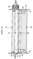
- Fig. 6 is a plan view of the fixing device shown in
Fig. 2 taken from the top;
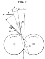
- Fig. 7 is a schematic illustration for explaining other
features of the present invention;
- Fig. 8 is a diagram (table) showing the results of
experiments according to the present invention;
- Figs. 9(A), 9(B) are enlarged sectional views of the
peeling member according to the present invention;
- Figs. 10(A), 10(B) are enlarged sectional views of a
conventional peeling member;
- Fig. 11 is a schematic illustration for explaining the
problem to be solved by the present invention;
- Fig. 12 is a sectional view showing an embodiment of
the present invention; and
- Fig. 13 is a sectional view showing another embodiment
of the present invention.
-
DESCRIPTION OF THE PREFERRED EMBODIMENTS
-
Hereinafter, embodiments of the present invention will
be described with reference to the attached drawings. Fig.
1 is an illustration of the entire structure of an image
forming apparatus, showing an embodiment of a fixing device
according to the present invention.
-
In an apparatus body 2 of an image forming apparatus
1, an image carrier 3 consisting of a photosensitive drum
is arranged and is driven to rotate in a direction of an arrow,
shown in Fig. 1, by a driving means (not shown). Arranged
around the image carrier 3, along the rotational direction
thereof, are a charging device 4 for uniformly charging the
image carrier 3, an exposure device 5 for forming a
electrostatic latent image on the image carrier 3, a rotary
developing device 6 for developing the electrostatic latent
image, and an intermediate transfer device 7 for primary
transfer of a unicolor toner image formed on the image carrier
3.
-
The rotary developing device 6 comprises a yellow
developing unit 6Y, a magenta developing unit 6M, a cyan
developing unit 6C, and a black developing unit 6B which are
attached to a support frame 8. The support frame 8 is driven
to rotate by a driving motor (not shown). The rotary
developing device 6 is rotated and moved such that one of
these developing units 6Y, 6C, 6M, 6K is selectively disposed
to face the image carrier 3 for every rotation of the image
carrier 3. Each of the developing units 6Y, 6C, 6M, 6K has
a toner storage portion for storing toner of the
corresponding color.
-
The intermediate transfer device 7 comprises a driving
roller 9 and a driven roller 10, an intermediate transfer
belt 11 to be driven by the two rollers in a direction of
an arrow, shown in Fig. 1, a primary transfer roller 12 which
is disposed on the back of the belt 11 at a position
corresponding to the image carrier 3, a transfer belt cleaner
13 for removing residual toner on the belt 11, and a secondary
transfer roller 14 which is disposed opposite to the driving
roller 9 to transfer a full color image of four colors formed
on the intermediate transfer belt 11 onto a recording medium
(such as a paper sheet).
-
A sheet cassette 15 is arranged at a bottom portion
of the apparatus body 2 . Recording media in the sheet cassette
15 are fed one by one to an outfeed tray 20 through a pickup
roller 16, a recording media feeding path 17, a secondary
transfer roller 14, and a fixing device 19. Numeral 23
designates a dual-side printing passage.
-
The actions of the image forming apparatus having the
aforementioned structure will be explained below. As an image
forming signal is inputted into a control unit from a computer
(not shown), the image carrier 3, the respective development
rollers 6a of the developing device 6, and the intermediate
transfer belt 11 are driven to rotate. The outer surface of
the image carrier 3 is uniformly charged by the charging device
4. The outer surface of the image carrier 3 is exposed to
selective light corresponding to image information for the
first color (e.g. yellow) by the exposure device 5, thereby
forming an electrostatic latent image for yellow.
-
The yellow developing unit 6Y is moved so that its
developing roller 6a is brought in contact with a portion of
the image carrier 3 where the electrostatic latent image has
been formed, thereby forming an yellow toner image on the image
carrier 3. The toner image thus formed on the image carrier
3 is transferred to the intermediate transfer belt 11 by the
primary transfer roller 12. During this, the secondary
transfer roller 14 is spaced apart from the intermediate
transfer belt 11.
-
In response to image forming signals for the second
color, the third color, and the fourth color, the processes
of the latent image formation, the development, the transfer
according to the rotation of the image carrier 3 and the
intermediate transfer belt 11 are repeated, whereby toner
images of four colors corresponding to the image forming
signals are transferred to and superposed on the intermediate
transfer belt 11. In synchronization with the movement of the
full-color image reaching the secondary transfer roller 14,
a receiving medium is fed to the secondary transfer roller
14 through the feeding passage 17. At this point, the secondary
transfer roller 14 is pressed against the intermediate
transfer belt 11 and a secondary transfer voltage is applied,
whereby the full-color toner image on the intermediate
transfer belt 11 is transferred to the recording medium. The
toner image transferred to the recording medium is heated and
pressed by the fixing device 19 so that the toner image is
fixed. Residual toner on the intermediate transfer belt 11
is removed by the transfer belt cleaner 13.
-
In case of dual-side printing, the recording medium
after the fixing device 19 is switched back and supplied to
the secondary transfer roller 14 through the dual-side
printing passage 23. At the secondary transfer roller 14, a
full-color toner image on the intermediate transfer belt 11
is transferred to the recording medium and is again heated
and pressed to be fixed at the fixing device 19.
-
In Fig. 1, the fixing device 19 according to the present
invention comprises a heating fixing member 21 composed of
a fuser roller having a heat source and a pressure member 22
composed of a pressure roller to be pressed against the fuser
roller. The fuser roller 21 and the pressure roller 22 are
arranged such that the angle formed between a line connecting
the axis of the fuser roller 21 and the axis of the pressure
roller 22 and a horizontal line becomes . The angle is
defined as 0° ≤ ≤ 30°.
-
Fig. 2 through Fig. 6 show the detail of the fixing
device 19 shown in Fig. 1. Fig. 2 is a perspective view showing
the fixing device with being partially broken away, Fig. 3
is a sectional view of main parts of the device, Fig. 4 is
a perspective view of a peeling member shown in Fig. 2, Fig.
5 is a side view showing an installation state of the peeling
member, and Fig. 6 is a plan view of the fixing device shown
in Fig. 2 taken from the top. In these drawings, the same
parts are designated with the same numerals and the
description about such parts will be omitted.
-
In Fig. 2 and Fig. 6, the fuser roller 21 is rotatably
disposed in a housing 24. Connected to one side of the fuser
roller 21 is a driving gear 28. The pressure roller 22 is
rotatably disposed to face the fuser roller 21. The length
of the pressure roller 22 in the axial direction is shorter
than that of the fuser roller 21. Bearings 25 are arranged
in spaces formed because of difference in length so that the
pressure roller 22 is supported by the bearings 25 at both
ends of the pressure roller 22. A pressure lever 26 is
rotatably disposed on each bearing 25 and a pressure spring
27 is disposed between one end of the pressure lever 26 and
the housing 24, whereby the pressure roller 22 and the fuser
roller 21 are pressed against each other.
-
In Fig. 3, the fuser roller 21 comprises a cylindrical
body 21b made of a metal having a heat source 21a such as
a halogen lamp therein, an elastic layer 21c made of silicone
rubber or the like provided on the outer periphery of the
cylindrical body 21b, an outer layer (not shown) made of
fluoro rubber, fluoro resin (e.g. Polytetra Fluoroethylene
(PTFE)) coating on the surface of the elastic layer 21c, and
a rotary shaft 21d fixed to the cylindrical body 21b.
-
The pressure roller 22 comprises a cylindrical body
22b made of a metal, a rotary shaft 22d fixed to the
cylindrical body 22b, the bearings 25 supporting the rotary
shaft 22d, an elastic layer 22c provided on the outer
periphery of the cylindrical body 22b, and an outer layer
(not shown) made of fluoro rubber, fluoro resin coating on
the surface of the elastic layer 22c, similarly to the fuser
roller 21. The thickness of the elastic layer 21c of the fuser
roller 21 is extremely smaller than the thickness of the
elastic layer 22c of the pressure roller 22, thereby forming
a fixing nip portion N where the pressure roller 22 is
concaved.
-
As shown in Fig. 2 and Fig. 3, supporting shafts 29,
30 are disposed on both sides of the housing 24. A peeling
member 31 for the fuser roller 21 and a peeling member 32
for the pressure roller 22 are attached to the supporting
shafts 29, 30, respectively such that the peeling members
31, 32 are pivotable. That is, the peeling members 31, 32
are arranged on downstream side in the recording medium
feeding direction of the nip portion to extend in the axial
direction of the fuser roller 21 and the pressure roller 22.
-
The peeling member 31 for the fuser roller 21 has a
resin sheet or a metal sheet as a substrate and a fluoro resin
layer formed on the surface of the substrate, as shown in
Fig. 4 and Fig. 5. The peeling member 31 comprises a plate-like
peeling portion (substrate) 31a, a bent portion 31b which
is positioned behind the peeling portion 31a and is bent into
L-like shape toward the fuser roller 21, supporting pieces
31c which are positioned on both sides of the peeling portion
31a and are bent downward, fitting holes 31d formed in the
supporting pieces 31c, and guide portions 31e which are
positioned on both sides of the peeling portion 31a to extend
forward.
-
The peeling portion 31a is arranged to be inclined
toward the outlet of the nip portion N such that the end of
the peeling portion 31a is in non-contact with and in
proximity to the fuser roller 21. The supporting shafts 29
described above with regard to Fig. 3 are fitted into the
fitting holes 31d. The guide portions 31e are biased toward
the housing 24 by springs 33, whereby the ends of the guide
portions 31e are in contact with the fuser roller 21. As a
result, the gap between the end of the peeling portion 31a
and the surface of the fuser roller 21 is always held constant.
-
The peeling member 32 for the pressure roller 22 has
a similar configuration as the peeling member for the fuser
roller 21. As shown in Fig. 2 and Fig. 3, the end of a peeling
portion 32a is positioned on the further downstream side in
the recording medium feeding direction relative to the end
of the peeling portion 31a. The ends of guide portions 32e
are in contact with the outer peripheries of the bearings
25 of the pressure roller 22 at points P, whereby the gap
between the end of the peeling portion 32a and the surface
of the pressure roller 22 is always held constant.
-
Now, characteristics of the present invention will be
described. Conventionally, since the fuser roller 21 and the
pressure roller 22 are generally arranged one above the other
to be aligned in the vertical direction, a force acts on the
recording medium, going out of the nip portion, in a direction
moving apart from the fuser roller 21 because of gravitation
so that the prospect of peeling the recording medium by the
peeling member is low. However, when the fuser roller 21 and
the pressure roller 22 are aligned in substantially the
horizontal direction so that the recording medium feeding
direction is substantially the vertical direction as shown
in Fig. 1, the recording medium easily winds around the fuser
roller 21. Further, in case of dual-side printing, there is
also a problem that toner on the pressure roller 22 side
corresponding to locations where no toner is transferred on
the fuser roller 21 is fused so that the recording medium
easily winds around the pressure roller 22. It may be
conceived that another peeling member 32 is provided on the
pressure roller 22 side. However, similarly to the peeling
member on the fuser roller 21 side, there is a problem that
a gap between the end of the peeling member and the pressure
roller must be held always constant.
-
Therefore, according to the present invention, the
peeling members 31, 32 are arranged on the downstream side
in the recording medium feeding direction relative to the
nip portion N to extend in the axial direction of the fuser
roller 21 and the pressure roller 22. The end portion of the
peeling member 31 for the fuser roller 21 is arranged to be
inclined toward the outlet of the nip portion N such that
the end of the peeling portion 31a is in non-contact with
and in proximity to the fuser roller 21. The end of the peeling
member 32 for the pressure roller 22 is positioned on the
further downstream side in the recording medium feeding
direction relative to the end of the peeling member 31.
-
As shown in Fig. 5, the peeling member 31 for the fuser
roller 21 is biased toward the housing 24 by the springs 33,
whereby the ends of the guide portions 31e are in contact
with the fuser roller 21. As a result, the gap between the
end of the peeling portion 31a and the surface of the fuser
roller 21 is positioned to be always held constant.
-
The peeling member 32 for the pressure roller 22 has
a similar configuration as the peeling member for the fuser
roller 21. As shown in Fig. 2 and Fig. 3, the end of the peeling
portion 32a is positioned on the further downstream side in
the recording medium feeding direction relative to the end
of the peeling portion 31a. The ends of the guide portions
32e are in contact with the outer peripheries of the bearings
25 of the pressure roller 22 at the points P, whereby the
gap between the end of the peeling portion 32a and the surface
of the pressure roller 22 is positioned to be always held
constant. Therefore, as shown in Fig. 6, the length of the
pressure roller 22 in the axial direction is shorter than
that of the fuser roller 21. The bearings 25 are arranged
in spaces formed because of difference in length so that the
pressure roller 22 is supported by the bearings 25 at both
sides of the pressure roller 22.
-
In case of dual-side printing, a recording medium of
which one side is printed is peeled off by the peeling member
31 for the fuser roller 21. After that, the recording medium
is switched back such that the forward end of the recording
medium becomes the rear end and is supplied to the secondary
transfer roller 14 through the dual-side printing passage 23.
At the secondary transfer roller 14, a full-color toner image
on the intermediate transfer belt 11 is transferred to the
recording medium and is again heated and pressed by the fuser
roller 21 so that the image is fixed. The recording medium
adhering to and winding around the pressure roller 22 during
this fixing process is peeled off by the peeling member 32
for the pressure roller 22.
-
Now, the other characteristics of the present invention
will be described. As shown in Fig. 7, in case that the fuser
roller 21 and the pressure roller 22 are aligned in
substantially the horizontal direction and a method of feeding
a recording medium out of the fixing nip N upwardly is employed,
the recording medium easily winds around the fuser roller 21
so that the recording medium always comes in contact with the
peeling member 31, that is, the frequency in use of the peeling
member is high. In this case, the setting of the alignment
angle of the peeling member relative to the recording medium
is important. If the alignment angle of the peeling member
31 relative to the recording medium is not good, the peeling
performance of recording media should be poor and linear
defects may be created on image.
-
Therefore, in the present invention, evaluation tests
for the alignment angle of the peeling member 31 with respect
to the recording medium have been conducted with various
angles of the peeling member 31 relative to the tangent line
S of the outlet of the fixing nip portion N. Fig. 8 shows the
results of the evaluation tests. From the results, it is found
that good peeling performance without linear defects can be
obtained when the alignment angle of the peeling member 31
is set in a range -5° ≤ ≤ 25° relative to the tangent line
S of the outlet of the fixing nip portion N. It should be noted
that the angle is expressed with "+" for the fuser roller 21
side and "-" for the pressure roller 22 side.
(Example 1)
-
- Fuser Roller
- Diameter: 30 mm,
- Elastic with a layer: silicone rubber (JIS-A hardness: 5°) thickness of 1 mm,
- Outer layer: PFA (tetrafluoroethylene/perfluoroalkyl vinyl ether copolymer) with a thickness of 40 µm, with a built-in heater.
- Pressure Roller
- Diameter: 35 mm,
- Elastic layer: silicone rubber (JIS-A hardness: 10°) with a thickness of 6 mm,
- Outer layer: PFA with a thickness of 40 µm.
-
-
Distance between the outlet of the fixing nip and the end
of the peeling portion 31a: 6.5 mm, Width of the fixing nip:
8 mm, Fusing Temperature: 185°C, Sheet feeing speed: 215 mm/s,
Pressure load on the rollers: 31 kgf.
(Example 2)
-
- Fuser Roller
- Diameter: 40 mm,
- Elastic with a layer: silicone rubber (JIS-A hardness: 8°) thickness of 1.5 mm,
- Outer layer: PFA with a thickness of 40 µm, Built-in heater.
- Pressure Roller
- Diameter: 50 mm,
- Elastic layer: silicone rubber (JIS-A hardness: 10°)
with a thickness of 6 mm,
- Outer layer: PFA with a thickness of 40 µm.
-
-
Distance between the outlet of the fixing nip and the end
of the peeling portion 31a: 6.5 mm, Width of the fixing nip:
8 mm, Fusing Temperature: 185°C, Sheet feeing speed: 215 mm/s,
Pressure load on the rollers: 26 kgf.
(Example 3)
-
- Fuser Roller
- Diameter: 30 mm,
- Elastic layer: silicone rubber (JIS-A hardness: 5°) with a thickness of 1 mm,
- Outer layer: PFA with a thickness of 40 µm, Built-in heater.
- Pressure Roller
- Diameter: 35 mm,
- Elastic layer: silicone rubber (JIS-A hardness: 10°) with a thickness of 6 mm,
- Outer layer: PFA with a thickness of 40 µm.
-
-
Distance between the outlet of the fixing nip and the
end of the peeling portion 31a: 7.5 mm, Width of the fixing
nip: 8 mm, Fusing Temperature: 185°C, Sheet feeing speed:
215 mm/s, Pressure load on the rollers: 31 kgf.
Evaluation items
-
- (1) Linear defects on image: a full solid image was printed
and "linear defects" as scratch marks by the peeling portion
31a were visually observed and evaluated.
- ○: no linear defects
- Δ: minor light linear defects
- ×: deep and severe linear defects
- (2)Peeling performance: a full solid image was successively
printed on 250 sheets of paper and the number of failures
of feeding operation of the fixing device was counted.
- o ○ : no failure
- ○: one or two sheets having dog ear
- Δ: three or four sheets having dog ear
- ×: five or more sheets having dog ear or paper jam
-
-
Hereinafter, the peeling member according to the
present invention will be explained. As shown in Fig. 9(A),
the peeling member 31 according to the present invention
comprises a substrate 31a having an edge E on the end thereof
and a fluoro resin layer 31f formed on the surface of the
substrate 31a. Even if an end portion of the resin layer 31f
coming in contact with the recording medium is removed due
to wear by repeated use over the years as shown in Fig. 9(B),
the recording medium comes in linear contact with the peeling
member 31 at the edge E so as to prevent toner adhesion and
prevent the creation of linear defects, thereby improving
the durability of the peeling member 31.
-
The substrate 31a of the peeling member 31 may be made
of a metal such as stainless steel, nickel, aluminum, and iron,
or a resin such as polyester and polyimide. The Edge E at the
end of the substrate 31a is processed by a high-precision
finishing such as mechanical grinding, electrolytic grinding,
and etching.
-
Examples of the material of the fluoro resin layer 31f
include thermoplastic fluoro resins such as
tetrafluoroethylene/perfluoroalkyl vinyl ether copolymer
(PFA), tetrafluoroethylene resin (PTFE),
tetrafluoroethylene hexafluoropropylene copolymer (FEP),
ehtylene tetrafluoroethylene copolymer (ETFE), ethylene
chlorotrifluoroethylene copolymer (ECTFE),
Polychlorotrifluoroethylene (PCTFE), polyvinyl fluoride
(PVF), tetrafluoroethylene hexafluoropropylene
perfluoroalkoxy vinyl ether copolymer (EPE), and
polyvinylidene fluoride resin (PVDF), thermoplastic
elastomers, other fluoro copolymer resins, and fluorocarbon
such as (CF)N and (C2F)F.
-
Now, description will be made as regard to the control
of the gap between the end of the peeling member and the fuser
roller according to the present invention. For peeling off
a recording medium from the fuser roller 21 with even force
over the entire width of the fuser roller 21, the gap between
the end of the peeling member 31 and the fuser roller 21 must
be held always constant over the entire length in the axial
direction of the fuser roller 21. In addition, as shown in
Fig. 11, the fuser roller 21 and the pressure roller 22 are
normally biased against each other by force F of the springs
27 (Fig. 2) at the both ends in the axial direction of the
rollers so that the middle portion of the pressure roller 22
bulges because the elastic layer of the pressure roller 22
is thick. As a result of this, the surface of the fuser roller
21 is deflected into an arc shape in the axial direction.
Therefore, there is a problem that it is very difficult to
control the gap between the peeling member 31 and the surface
of the fuser roller 21.
-
Conventionally, since the fuser roller 21 and the
pressure roller 22 are generally arranged one above the other
to be aligned in the vertical direction, a force acts on the
recording medium, going out of the nip portion, in a direction
moving apart from the fuser roller because of gravitation so
that the prospect of peeling the recording medium by the
peeling member is low. However, when the fuser roller 21 and
the pressure roller 22 are aligned in substantially the
horizontal direction as shown in Fig. 1, the recording medium
easily winds around the fuser roller 21 so that the recording
medium going out of the nip portion N always comes in contact
with the peeling member, that is, the frequency in use of the
peeling member is extremely high as compared to the
conventional one. Accordingly, the control of the
aforementioned gap is a matter of further importance.
-
The aforementioned problem is solved by the present
invention as the following manner. Fig. 12 is a sectional view
showing one embodiment of the present invention. As mentioned
above, the fuser roller 21 is biased against the pressure
roller 22 by force F of the springs 27 (Fig. 2) at the both
ends in the axial direction thereof, the longitudinal section
through the axis of the metal cylindrical body 21b is formed
in a hourglass-like shape and the surface of the elastic layer
22c is formed in an arc shape. In addition, the fuser roller
21 is frequently formed in an inversed crown shape (having
side portions of which diameter is larger than that of the
middle portion thereof) for preventing the creation of creases.
This also increases the tendency of arc shape. In this
embodiment, the end portion 31f of the peeling member 31 is
formed in an arc shape in order to make the gap G between the
end portion 31f of the peeling member 31 and the elastic layer
22c constant. The gap G is measured by a micro gauge or a laser
displacement gauge.
-
Fig. 13 is a sectional view of another embodiment of
the present invention. In this embodiment, the end portion
31f of the peeling member 31 is formed such that gap G2 between
the end of the peeling member 31 and the surface of the fuser
roller 21 at the both side portions thereof is greater than
the gap G1 between the end of the peeling member 31 and the
surface the fuser roller 21 at the middle portion thereof.
In this embodiment, the middle portion of the peeling member
31 (the portion first comes in contact with the recording
medium) is proximal to the fuser roller 21. In this structure,
the control of the gap is facilitated so that the peeling
member 31 can be easily manufactured without losing
substantial peeling performance. Since the portion in
proximity to the fuser roller 21 is reduced, the damage of
the peeling member 31 and the fuser roller 21 due to object
matters or paper jam is reduced, thereby improving the
durability and the reliability of the peeling member 31 and
the fuser roller 21.
-
Though the present invention has been described with
reference to the embodiments disclosed herein, the present
invention is not limited thereto and various changes may be
made therein. The present invention may be adopted to
conventionally known techniques and these techniques may be
combined. For example, though the peeling member 31 for the
fuser roller 21 has bee explained in the aforementioned
embodiments, the present invention may be adopted to the
peeling member 32 for the pressure roller 22.