EP1345010A2 - Method and apparatus for calibrating a position transducer - Google Patents
Method and apparatus for calibrating a position transducer Download PDFInfo
- Publication number
- EP1345010A2 EP1345010A2 EP03005241A EP03005241A EP1345010A2 EP 1345010 A2 EP1345010 A2 EP 1345010A2 EP 03005241 A EP03005241 A EP 03005241A EP 03005241 A EP03005241 A EP 03005241A EP 1345010 A2 EP1345010 A2 EP 1345010A2
- Authority
- EP
- European Patent Office
- Prior art keywords
- calibration
- position transducer
- error
- normal
- controller
- Prior art date
- Legal status (The legal status is an assumption and is not a legal conclusion. Google has not performed a legal analysis and makes no representation as to the accuracy of the status listed.)
- Withdrawn
Links
Images

Classifications
-
- G—PHYSICS
- G01—MEASURING; TESTING
- G01D—MEASURING NOT SPECIALLY ADAPTED FOR A SPECIFIC VARIABLE; ARRANGEMENTS FOR MEASURING TWO OR MORE VARIABLES NOT COVERED IN A SINGLE OTHER SUBCLASS; TARIFF METERING APPARATUS; MEASURING OR TESTING NOT OTHERWISE PROVIDED FOR
- G01D18/00—Testing or calibrating apparatus or arrangements provided for in groups G01D1/00 - G01D15/00
Definitions
- This invention relates to apparatus and method for calibrating transducers.
- Transducers are used in a variety of applications to measure such things as position, pressure, or other physical or environmental characteristics.
- Position transducers for example, detect positional movement in a variety of applications.
- One example position transducer is disclosed in U.S. Patent No 5,965,879 (the '879 patent) and provides high sensitivity optical encoding.
- Such encoders have application in ultra-high precision, two-axis scanning mirror mechanisms.
- high resolution position transducers are extremely difficult to calibrate primarily because the test equipment must perform with greater precision than the transducer being tested.
- the direct measurement technique of prior calibration systems was a static operation. It required external devices to measure the error, which external devices had to have a higher accuracy than the system under calibration. For standard optical encoder systems, for example, devices such as theodolites were commonly used to provide high accuracy for calibration. Ultimately, devices which were costly, bulky, and complex were required to make direct measurement on the target system, which test devices were not only expensive but also difficult to perform in-situ. In addition, the direct measurement technique was time consuming. Many measurements had to be made over the range of travel when errors had high spatial frequencies, as was the case with high resolution encoders. If the number of direct measurements was small to keep the test time low, interpolation of the data was required, which induced calibration error. Further, independent measurement devices required alignment by error-prone human operators.
- the repetitive control technique had limited capability to correct error in measurements because the control bandwidth was very low. In such a system, sampling had to be kept at a low frequency in order to stay within appropriate Nyquist control characteristics (i.e., to remain stable). As a result, the repetitive calibration system did not accurately correct error signals outside of a low bandwidth. Further, an accurate measurement using servo error was not always possible because the amplitude and phase of the signal source appeared attenuated, amplified, or phase-shifted, depending upon frequency.
- testing of the encoders in the HIRDLS system revealed a 0.6 arc seconds peak-to-peak cyclical error.
- NASA brought in a new technology encoder to provide independent, high accuracy data.
- the test set up with both the operational encoder and the calibration encoder was used exhaustively over several months to characterize the nature of the cyclical error in the HIRDLS encoder.
- an example embodiment of the present invention can perform the same test in a matter of hours without the need for the special calibration encoder.
- substantial savings can be realized in that a highly precise calibration encoder is not required in order to resolve repeatable errors.
- the calibration of a position transducer can be performed quickly, inexpensively, and in-situ.
- the present invention as described in claims 1, 8 or 16 provides calibration of repeatable errors in position transducers in a much preferable manner compared to either the direct measurement technique or the repetitive control technique of prior devices.
- direct measurements of error are taken in closed loop servo conditions.
- no additional high precision calibration system is required, and tests can be performed quickly, inexpensively, and in-situ.
- the present invention is not limited to calibration at only low control bandwidths.
- calibration of repeatable errors in position transducers is performed dynamically, in-situ under closed loop servo operation.
- the closed loop servo operation eliminates the man in the loop and allows for automatic, rapid, real-time measurement of the repeatable error.
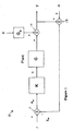
- a relevant closed loop servo configuration is shown in Figure 1.
- a measured plant output y m is subtracted from a reference signal r at the summing device 11 of the loop 10.
- the output of the summing device 11 is the measured or servo error e m , which is input into controller K yielding the plant input control signal u.
- the plant input control signal u is input to plant G, the output of which is provided to the summing device 12.
- Disturbance transfer function G d operates on a disturbance signal d to provide the other input to the summing device 12.
- the output is the plant output y .
- the plant output y is summed at summing device 13 with a position transducer measurement error signal n to create the measured plant output y m that is fed back into the summing device 11.
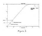
- S (1 + GK ) -1 is the sensitivity function.
- Figure 2 shows a typical sensitivity function with the desired frequency separation.
- the presumption regarding the low bandwidth controller allows the error to appear with near unity gain and nearly 180° phase shift in the servo error signal.
- the second presumption regarding the constant rate position command guarantees that
- the position transducer 26 is a known position transducer to be calibrated by the calibration system 20 in accordance with the preferred embodiment of the present invention. Such a position transducer may be like those described in the '879 patent.
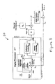
- digital processor 27 includes a calibration algorithm to perform the calibration test discussed previously. The digital processor 27 remains in-situ with the plant 25 and position transducer 26 to operate in either a normal mode or a calibration mode for the position transducer 26.
- the normal mode is selected by operation of the switches 28A and 28B being placed in the normal command position. In this position, the normal command is input to the summing device 22, which sums the normal command to the measured plant output y m to yield the servo error.
- the servo error signal is input to the normal controller 24, which is selected by the switch 28B, the output of which is put into plant 25 and position transducer 26, respectively.
- the progression of the normal command, normal controller 24, plant 25, and position transducer 26 operate in accordance with known methodologies.
- the present invention adds an in-situ calibration routine in which the position transducer 26 may be calibrated in the loop.
- the switches 28A and 28B are switched to the calibration positions, connecting the calibration command from the calibration algorithm 21 into the summing device 22, which sums the calibration command and the measured plant output y m into the summing device 22.
- the result is the servo error signal, which is fed to the calibration controller 23 and to the calibration algorithm 21.
- the calibration controller 23 provides an output to the plant 25, and the position transducer 26, yielding the plant output signal y m , which is fed back to the summing device 22.
- the calibration algorithm controls the sequencing and processing when calibration is selected.
- the normal controller 24 is replaced with the special calibration controller 23, and then the calibration algorithm performs the error calibration.
- the calibration algorithm stores the measured servo error and the corresponding position transducer output y m .
- the loop is reconfigured to its normal controller when calibration is complete, by operation of the switches 28A and 28B.
- the details of the calibration algorithm are shown in Figure 4.
- the steps of Figure 4 begin when the switches 28A and 28B move to the calibration position such that the control loop configuration is switched from its normal controller 24 to the special calibration controller 23 at step 30.
- the constant rate calibration command (CAL CMD) profile from the calibration algorithm 21 is then injected into the loop at step 31 ( Figure 3).
- the command profile may be triangular (back and forth motion) in nature for systems with limited travel or may be a constant rate position command for systems that have 360 degree rotational capability.
- the servo error and transducer output ( y m ) are recorded at step 32 as a function of the measured position y m .
- the algorithm averages the stored data at step 33, thereby reducing the effect of unwanted noise in the measurements through averaging.
- the measured position transducer error is stored as a function of position transducer output in a table at step 34.
- a table is described with respect to step 34, the data may alternatively be curve fit, if appropriate.
- the normal controller 24 is then switched back into the loop at step 35.
- the calibration algorithm uses the position transducer output as the input to a table lookup whose output is used as the error correction value ( Figure 3), and is injected back into the loop by the calibration algorithm via the summing device 22 to compensate for the raw error detected by the calibration algorithm 21.
Landscapes
- Physics & Mathematics (AREA)
- General Physics & Mathematics (AREA)
- Control Of Position Or Direction (AREA)
Abstract
Description
In addition, the direct measurement technique was time consuming. Many measurements had to be made over the range of travel when errors had high spatial frequencies, as was the case with high resolution encoders. If the number of direct measurements was small to keep the test time low, interpolation of the data was required, which induced calibration error. Further, independent measurement devices required alignment by error-prone human operators.
- FIGURE 1
- is a closed loop servo configuration in accordance with an example embodiment of the present invention;
- FIGURE 2
- is a typical sensitivity function showing frequency content separation within an example embodiment of Figure 1;
- FIGURE 3
- is an example embodiment of a calibration operation; and
- FIGURE 4
- is an example embodiment of a present calibration algorithm.

By selecting a reference r such that
Claims (20)
- A calibration system (10) for a servo controlled mechanism containing a position transducer with a repeatable error and being influenced by an external disturbance, comprising:a closed loop having a normal operation and a calibration operation;an input to the closed loop, said input being a normal command during the normal operation and a calibration command during the calibration operation;a calibration system (21) producing the calibration command, measuring the repeatable error during the calibration operating function, storing a characteristic of the measured repeatable error (em), and injecting a calibration adjustment based on the stored characteristic into the closed loop during the normal operation; anda controller (20) in the closed loop having a sensitivity function that approximates a natural value at the frequency of the position transducer repeatable error and, in absolute value, is lower at the frequencies of the normal command input and of the external disturbance.
- A system as in claim 1, wherein the servo controlled mechanism contains a position transducer (26).
- A system as in claim 1, wherein the controller includes a normal controller (24) and a calibration controller (23), selected based upon a mode of operation.
- A system as in claim 1, wherein the calibration system (21) and at least part of the controller are included in a common digital processor (27).
- A system as in claim 3, wherein the calibration system (21), normal controller (24) and calibration controller (23) are included in a common digital processor.
- A system as in claim 3, further including a switch (28A, 28B)to simultaneously select:the input as between the normal command or the calibration command (28A), andthe controller as between the normal controller or the calibration controller (28B).
- A system as in claim 1, wherein the sensitivity function is nearly equal to one at the lowest frequency of the position transducer repeatable error.
- A method of calibrating, within a servo loop, a position transducer exhibiting a repeatable error, comprising the steps of:providing a closed loop;in a calibration operation:inputting to the closed loop a calibration reference signal;adjusting the calibration reference signal by a feedback signal from the servo controlled mechanism;measuring the position transducer repeatable error under conditions such that the adjusted signal is dominated by a measurement of the repeatable error; andstoring the characteristics of the measured repeatable error; and in a normal operation:inputting to the closed loop a normal reference signal;inputting to the closed loop a position transducer calibration adjustment based on the stored characteristics;adjusting the normal reference signal by the fine calibration adjustment and the feedback signal; andproviding a controlled version of the adjusted normal reference signal to the servo controlled mechanism.
- A method as in claim 8, wherein the step of inputting to the closed loop the fine calibration adjustment during normal operation includes inputting the position transducer error measurement based on the stored characteristic.
- A method as in claim 8, further including:in the calibration operation, controlling the adjusted calibration reference signal in a calibration controller within the loop prior to input into the servo controlled mechanism.
- A method as in claim 10, wherein the calibration controller exhibits a sensitivity function that approximates a natural value at the frequency of the position transducer repeatable error and, in absolute value, is lower at the frequency of the normal reference signal than at the frequency of the position transducer repeatable error.
- A method as in claim 11, further including:in the normal operation, controlling the adjusted normal reference signal in a normal controller within the loop prior to input into the servo controlled mechanism.
- A method as in claim 8, further including:in the calibration operation, controlling the adjusted calibration reference signal in a calibration controller within the loop prior to input into the servo controlled mechanism;in the normal operation, controlling the adjusted normal reference signal in a normal controller within the loop prior to input into the servo controlled mechanism; andtime sharing the loop between the normal operation and the calibration operation in-situ.
- A method as in claim 13, wherein the calibration controller exhibits a sensitivity function that approximates a natural value at the frequency of the repeatable error and, in absolute value, is lower at a frequency of the normal reference signal than at a frequency of the position transducer repeatable error.
- A method as in claim 14, wherein the sensitivity function nearly equals one at the lowest frequency of the position transducer repeatable error.
- An in-situ calibration system for a position transducer (26) exhibiting a repeatable error source, comprising:a feedback loop including a feedback signal from the position transducer; an input to the feedback loop, comprising a reference signal during a normal operation and a calibration signal during a calibration operation;a feedback node (22) combining the input and the feedback signal into a servo error signal;a controller (21) receiving the servo error signal in the loop, said controller operating during a calibration operating condition to selectively provide calibration control parameters into the loop, and during a normal operating condition, different from the calibration operating condition, to selectively provide normal control parameters into the loop; anda calibration utility injecting the calibration signal into the loop during the calibration operation, determining a position transducer error correction associated with the repeatable error source, and during a next normal operation, injecting a position transducer error correction signal related to said determination into the loop, wherein:the reference signal is selected such that the position transducer error correction dominates the servo error signal during the calibration operation.
- A system as in claim 16, wherein the calibration utility produces a sensitivity function that ensures the position transducer repeatable error dominates the servo error signal during the calibration operation.
- A system as in claim 16, wherein the position transducer (26) is influenced by an external disturbance input frequency and wherein the calibration utility produces a sensitivity function whose absolute value at the external disturbance input frequency and whose absolute at a frequency of the reference signal are considerably less than the absolute value at a lowest frequency on the position transducer repeatable error.
- A system as in claim 18, wherein the reference signal ensures that the sensitivity function is essentially equal to a natural value near the frequency of the position transducer repeatable error.
- A system as in claim 19, wherein the sensitivity function is essentially equal to one near the frequency of the position transducer repeatable error.
Applications Claiming Priority (2)
| Application Number | Priority Date | Filing Date | Title |
|---|---|---|---|
| US95015 | 1987-09-10 | ||
| US10/095,015 US6683461B2 (en) | 2002-03-12 | 2002-03-12 | Servo controlled calibration of repeatable errors in position transducers |
Publications (2)
| Publication Number | Publication Date |
|---|---|
| EP1345010A2 true EP1345010A2 (en) | 2003-09-17 |
| EP1345010A3 EP1345010A3 (en) | 2005-06-22 |
Family
ID=27765385
Family Applications (1)
| Application Number | Title | Priority Date | Filing Date |
|---|---|---|---|
| EP03005241A Withdrawn EP1345010A3 (en) | 2002-03-12 | 2003-03-10 | Method and apparatus for calibrating a position transducer |
Country Status (2)
| Country | Link |
|---|---|
| US (1) | US6683461B2 (en) |
| EP (1) | EP1345010A3 (en) |
Cited By (3)
| Publication number | Priority date | Publication date | Assignee | Title |
|---|---|---|---|---|
| CN102735284A (en) * | 2012-06-25 | 2012-10-17 | 青岛海信移动通信技术股份有限公司 | Method and device for calibrating sensor |
| CN107589396A (en) * | 2017-10-23 | 2018-01-16 | 国网江西省电力公司电力科学研究院 | A kind of dynamic property source tracing method based on conventional power calibration device |
| CN111742194A (en) * | 2019-06-12 | 2020-10-02 | 深圳市大疆创新科技有限公司 | Fault detection method, device and storage medium for encoder of removable platform |
Families Citing this family (3)
| Publication number | Priority date | Publication date | Assignee | Title |
|---|---|---|---|---|
| US20060271321A1 (en) * | 2005-05-24 | 2006-11-30 | Visteon Global Technologies, Inc. | Initiating calibration mode of electronic control module |
| CN105607024B (en) * | 2016-03-23 | 2018-03-27 | 吉林大学 | Calibration of Microwave Radiometer source polarization wiregrating rotation platform |
| CN107544245B (en) * | 2017-08-25 | 2020-08-04 | 浙江工业大学 | Discrete repetitive control method for motor servo system using first-order inertial attraction law with disturbance expansion compensation |
Family Cites Families (11)
| Publication number | Priority date | Publication date | Assignee | Title |
|---|---|---|---|---|
| US4338659A (en) | 1978-12-15 | 1982-07-06 | Fujitsu Fanuc Ltd. | Position control system for a closed loop type numerical-controlled machine tool |
| US4456863A (en) | 1980-12-23 | 1984-06-26 | Cleveland Machine Controls, Inc. | Apparatus for automatic calibration of servo response |
| US4446715A (en) | 1982-06-07 | 1984-05-08 | Camino Laboratories, Inc. | Transducer calibration system |
| US4852018A (en) | 1987-01-07 | 1989-07-25 | Trustees Of Boston University | Massively parellel real-time network architectures for robots capable of self-calibrating their operating parameters through associative learning |
| GB8806574D0 (en) | 1988-03-19 | 1988-04-20 | Hepworth Eng Ltd | Machine tool error compensation systems |
| US5483058A (en) | 1993-10-18 | 1996-01-09 | The United States Of America As Represented By The Administrator, National Aeronautics & Space Administration | High angular sensitivity, absolute rotary encoding device with polygonal mirror and stand-alone diffraction gratings |
| US5501512A (en) | 1995-06-27 | 1996-03-26 | Westinghouse Air Brake Company | System and method for automatically calibrating transducers in electro-pneumatic freight brake control systems |
| US5949605A (en) | 1996-03-19 | 1999-09-07 | Seagate Technology, Inc. | Cancellation and calibration procedures of harmonic disturbances in magnetic data storage systems |
| US5965879A (en) | 1997-05-07 | 1999-10-12 | The United States Of America As Represented By The Administrator Of The National Aeronautics And Space Administration | Method and apparatus for ultra-high-sensitivity, incremental and absolute optical encoding |
| US6029363A (en) * | 1998-04-03 | 2000-02-29 | Mitutoyo Corporation | Self-calibrating position transducer system and method |
| US5997778A (en) | 1998-04-23 | 1999-12-07 | Van Dorn Demag Corporation | Auto-tuned, adaptive process controlled, injection molding machine |
-
2002
- 2002-03-12 US US10/095,015 patent/US6683461B2/en not_active Expired - Fee Related
-
2003
- 2003-03-10 EP EP03005241A patent/EP1345010A3/en not_active Withdrawn
Cited By (4)
| Publication number | Priority date | Publication date | Assignee | Title |
|---|---|---|---|---|
| CN102735284A (en) * | 2012-06-25 | 2012-10-17 | 青岛海信移动通信技术股份有限公司 | Method and device for calibrating sensor |
| CN107589396A (en) * | 2017-10-23 | 2018-01-16 | 国网江西省电力公司电力科学研究院 | A kind of dynamic property source tracing method based on conventional power calibration device |
| CN107589396B (en) * | 2017-10-23 | 2019-12-06 | 国网江西省电力公司电力科学研究院 | dynamic performance tracing method based on conventional electric energy calibrator |
| CN111742194A (en) * | 2019-06-12 | 2020-10-02 | 深圳市大疆创新科技有限公司 | Fault detection method, device and storage medium for encoder of removable platform |
Also Published As
| Publication number | Publication date |
|---|---|
| US6683461B2 (en) | 2004-01-27 |
| US20030173974A1 (en) | 2003-09-18 |
| EP1345010A3 (en) | 2005-06-22 |
Similar Documents
| Publication | Publication Date | Title |
|---|---|---|
| US6487787B1 (en) | System and method for determination of error parameters for performing self-calibration and other functions without an external position reference in a transducer | |
| US6956505B2 (en) | Signal processing apparatus for encoder | |
| US6008902A (en) | Method and device for heterodyne interferometer error correction | |
| US5422829A (en) | Closed-loop control for scanning application | |
| US5978743A (en) | Self-calibration method for a sensor | |
| US4639774A (en) | Moving target indication system | |
| JPH10339650A (en) | Apparatus and method for automatically correcting scan signals containing errors in incremental position measurement devices | |
| JPH02504459A (en) | Subrange analog to digital converter with calibration | |
| WO1982003121A1 (en) | Bridge circuit compensation for environmental effects | |
| WO1999046578A9 (en) | A self-calibration approach for tunable laser spectral absorption sensors | |
| US4958294A (en) | Swept microwave power measurement system and method | |
| US8077080B2 (en) | Calibration to improve weather radar positioning determination | |
| US6683461B2 (en) | Servo controlled calibration of repeatable errors in position transducers | |
| US6784820B1 (en) | High resolution, high dynamic range analog-to-digital converter system and related techniques | |
| Dichev et al. | Analysis of instrumental errors influence on the accuracy of instruments for measuring parameters of moving objects | |
| US8816901B2 (en) | Calibration to improve weather radar positioning determination | |
| CN111412939B (en) | Real-time correction method and system for encoder | |
| JPH01160206A (en) | Calibrator and method of calibration for logarithmic amplifier | |
| US6807497B2 (en) | Laser measurement system with digital delay compensation | |
| US20230400305A1 (en) | Inertial measurement unit and method for operating a measurement unit | |
| KR20010071600A (en) | Method for calculating relative phases between signal channels in a multi-sensor tracking device | |
| US4078156A (en) | Drift cancellation circuit for multiplexer amplifier | |
| US7092833B2 (en) | Method and circuit for linearizing nonlinear curves | |
| RU2269867C1 (en) | Method for determining error of amplitude digital angle transformers of tracking type | |
| RU2081232C1 (en) | Device for checking rail track position |
Legal Events
| Date | Code | Title | Description |
|---|---|---|---|
| PUAI | Public reference made under article 153(3) epc to a published international application that has entered the european phase |
Free format text: ORIGINAL CODE: 0009012 |
|
| AK | Designated contracting states |
Kind code of ref document: A2 Designated state(s): AT BE BG CH CY CZ DE DK EE ES FI FR GB GR HU IE IT LI LU MC NL PT SE SI SK TR |
|
| AX | Request for extension of the european patent |
Extension state: AL LT LV MK RO |
|
| PUAL | Search report despatched |
Free format text: ORIGINAL CODE: 0009013 |
|
| AK | Designated contracting states |
Kind code of ref document: A3 Designated state(s): AT BE BG CH CY CZ DE DK EE ES FI FR GB GR HU IE IT LI LU MC NL PT SE SI SK TR |
|
| AX | Request for extension of the european patent |
Extension state: AL LT LV MK RO |
|
| 17P | Request for examination filed |
Effective date: 20051222 |
|
| AKX | Designation fees paid |
Designated state(s): AT BE BG CH CY CZ DE DK EE ES FI FR GB GR HU IE IT LI LU MC NL PT SE SI SK TR |
|
| 17Q | First examination report despatched |
Effective date: 20061215 |
|
| RAP1 | Party data changed (applicant data changed or rights of an application transferred) |
Owner name: EXELIS INC. |
|
| STAA | Information on the status of an ep patent application or granted ep patent |
Free format text: STATUS: THE APPLICATION IS DEEMED TO BE WITHDRAWN |
|
| 18D | Application deemed to be withdrawn |
Effective date: 20141001 |