EP1344676A1 - Controller for electric automobile - Google Patents
Controller for electric automobile Download PDFInfo
- Publication number
- EP1344676A1 EP1344676A1 EP01980916A EP01980916A EP1344676A1 EP 1344676 A1 EP1344676 A1 EP 1344676A1 EP 01980916 A EP01980916 A EP 01980916A EP 01980916 A EP01980916 A EP 01980916A EP 1344676 A1 EP1344676 A1 EP 1344676A1
- Authority
- EP
- European Patent Office
- Prior art keywords
- control device
- node
- controller
- control
- electric car
- Prior art date
- Legal status (The legal status is an assumption and is not a legal conclusion. Google has not performed a legal analysis and makes no representation as to the accuracy of the status listed.)
- Withdrawn
Links
Images



Classifications
-
- B—PERFORMING OPERATIONS; TRANSPORTING
- B60—VEHICLES IN GENERAL
- B60L—PROPULSION OF ELECTRICALLY-PROPELLED VEHICLES; SUPPLYING ELECTRIC POWER FOR AUXILIARY EQUIPMENT OF ELECTRICALLY-PROPELLED VEHICLES; ELECTRODYNAMIC BRAKE SYSTEMS FOR VEHICLES IN GENERAL; MAGNETIC SUSPENSION OR LEVITATION FOR VEHICLES; MONITORING OPERATING VARIABLES OF ELECTRICALLY-PROPELLED VEHICLES; ELECTRIC SAFETY DEVICES FOR ELECTRICALLY-PROPELLED VEHICLES
- B60L15/00—Methods, circuits, or devices for controlling the traction-motor speed of electrically-propelled vehicles
- B60L15/20—Methods, circuits, or devices for controlling the traction-motor speed of electrically-propelled vehicles for control of the vehicle or its driving motor to achieve a desired performance, e.g. speed, torque, programmed variation of speed
-
- B—PERFORMING OPERATIONS; TRANSPORTING
- B60—VEHICLES IN GENERAL
- B60L—PROPULSION OF ELECTRICALLY-PROPELLED VEHICLES; SUPPLYING ELECTRIC POWER FOR AUXILIARY EQUIPMENT OF ELECTRICALLY-PROPELLED VEHICLES; ELECTRODYNAMIC BRAKE SYSTEMS FOR VEHICLES IN GENERAL; MAGNETIC SUSPENSION OR LEVITATION FOR VEHICLES; MONITORING OPERATING VARIABLES OF ELECTRICALLY-PROPELLED VEHICLES; ELECTRIC SAFETY DEVICES FOR ELECTRICALLY-PROPELLED VEHICLES
- B60L3/00—Electric devices on electrically-propelled vehicles for safety purposes; Monitoring operating variables, e.g. speed, deceleration or energy consumption
- B60L3/0023—Detecting, eliminating, remedying or compensating for drive train abnormalities, e.g. failures within the drive train
- B60L3/0084—Detecting, eliminating, remedying or compensating for drive train abnormalities, e.g. failures within the drive train relating to control modules
-
- B—PERFORMING OPERATIONS; TRANSPORTING
- B60—VEHICLES IN GENERAL
- B60L—PROPULSION OF ELECTRICALLY-PROPELLED VEHICLES; SUPPLYING ELECTRIC POWER FOR AUXILIARY EQUIPMENT OF ELECTRICALLY-PROPELLED VEHICLES; ELECTRODYNAMIC BRAKE SYSTEMS FOR VEHICLES IN GENERAL; MAGNETIC SUSPENSION OR LEVITATION FOR VEHICLES; MONITORING OPERATING VARIABLES OF ELECTRICALLY-PROPELLED VEHICLES; ELECTRIC SAFETY DEVICES FOR ELECTRICALLY-PROPELLED VEHICLES
- B60L3/00—Electric devices on electrically-propelled vehicles for safety purposes; Monitoring operating variables, e.g. speed, deceleration or energy consumption
- B60L3/0092—Electric devices on electrically-propelled vehicles for safety purposes; Monitoring operating variables, e.g. speed, deceleration or energy consumption with use of redundant elements for safety purposes
-
- B—PERFORMING OPERATIONS; TRANSPORTING
- B60—VEHICLES IN GENERAL
- B60L—PROPULSION OF ELECTRICALLY-PROPELLED VEHICLES; SUPPLYING ELECTRIC POWER FOR AUXILIARY EQUIPMENT OF ELECTRICALLY-PROPELLED VEHICLES; ELECTRODYNAMIC BRAKE SYSTEMS FOR VEHICLES IN GENERAL; MAGNETIC SUSPENSION OR LEVITATION FOR VEHICLES; MONITORING OPERATING VARIABLES OF ELECTRICALLY-PROPELLED VEHICLES; ELECTRIC SAFETY DEVICES FOR ELECTRICALLY-PROPELLED VEHICLES
- B60L3/00—Electric devices on electrically-propelled vehicles for safety purposes; Monitoring operating variables, e.g. speed, deceleration or energy consumption
- B60L3/04—Cutting off the power supply under fault conditions
-
- B—PERFORMING OPERATIONS; TRANSPORTING
- B60—VEHICLES IN GENERAL
- B60L—PROPULSION OF ELECTRICALLY-PROPELLED VEHICLES; SUPPLYING ELECTRIC POWER FOR AUXILIARY EQUIPMENT OF ELECTRICALLY-PROPELLED VEHICLES; ELECTRODYNAMIC BRAKE SYSTEMS FOR VEHICLES IN GENERAL; MAGNETIC SUSPENSION OR LEVITATION FOR VEHICLES; MONITORING OPERATING VARIABLES OF ELECTRICALLY-PROPELLED VEHICLES; ELECTRIC SAFETY DEVICES FOR ELECTRICALLY-PROPELLED VEHICLES
- B60L3/00—Electric devices on electrically-propelled vehicles for safety purposes; Monitoring operating variables, e.g. speed, deceleration or energy consumption
- B60L3/12—Recording operating variables ; Monitoring of operating variables
-
- B—PERFORMING OPERATIONS; TRANSPORTING
- B60—VEHICLES IN GENERAL
- B60L—PROPULSION OF ELECTRICALLY-PROPELLED VEHICLES; SUPPLYING ELECTRIC POWER FOR AUXILIARY EQUIPMENT OF ELECTRICALLY-PROPELLED VEHICLES; ELECTRODYNAMIC BRAKE SYSTEMS FOR VEHICLES IN GENERAL; MAGNETIC SUSPENSION OR LEVITATION FOR VEHICLES; MONITORING OPERATING VARIABLES OF ELECTRICALLY-PROPELLED VEHICLES; ELECTRIC SAFETY DEVICES FOR ELECTRICALLY-PROPELLED VEHICLES
- B60L50/00—Electric propulsion with power supplied within the vehicle
- B60L50/50—Electric propulsion with power supplied within the vehicle using propulsion power supplied by batteries or fuel cells
- B60L50/60—Electric propulsion with power supplied within the vehicle using propulsion power supplied by batteries or fuel cells using power supplied by batteries
- B60L50/61—Electric propulsion with power supplied within the vehicle using propulsion power supplied by batteries or fuel cells using power supplied by batteries by batteries charged by engine-driven generators, e.g. series hybrid electric vehicles
-
- B—PERFORMING OPERATIONS; TRANSPORTING
- B60—VEHICLES IN GENERAL
- B60L—PROPULSION OF ELECTRICALLY-PROPELLED VEHICLES; SUPPLYING ELECTRIC POWER FOR AUXILIARY EQUIPMENT OF ELECTRICALLY-PROPELLED VEHICLES; ELECTRODYNAMIC BRAKE SYSTEMS FOR VEHICLES IN GENERAL; MAGNETIC SUSPENSION OR LEVITATION FOR VEHICLES; MONITORING OPERATING VARIABLES OF ELECTRICALLY-PROPELLED VEHICLES; ELECTRIC SAFETY DEVICES FOR ELECTRICALLY-PROPELLED VEHICLES
- B60L7/00—Electrodynamic brake systems for vehicles in general
- B60L7/24—Electrodynamic brake systems for vehicles in general with additional mechanical or electromagnetic braking
- B60L7/26—Controlling the braking effect
-
- B—PERFORMING OPERATIONS; TRANSPORTING
- B60—VEHICLES IN GENERAL
- B60L—PROPULSION OF ELECTRICALLY-PROPELLED VEHICLES; SUPPLYING ELECTRIC POWER FOR AUXILIARY EQUIPMENT OF ELECTRICALLY-PROPELLED VEHICLES; ELECTRODYNAMIC BRAKE SYSTEMS FOR VEHICLES IN GENERAL; MAGNETIC SUSPENSION OR LEVITATION FOR VEHICLES; MONITORING OPERATING VARIABLES OF ELECTRICALLY-PROPELLED VEHICLES; ELECTRIC SAFETY DEVICES FOR ELECTRICALLY-PROPELLED VEHICLES
- B60L2240/00—Control parameters of input or output; Target parameters
- B60L2240/10—Vehicle control parameters
- B60L2240/36—Temperature of vehicle components or parts
-
- B—PERFORMING OPERATIONS; TRANSPORTING
- B60—VEHICLES IN GENERAL
- B60L—PROPULSION OF ELECTRICALLY-PROPELLED VEHICLES; SUPPLYING ELECTRIC POWER FOR AUXILIARY EQUIPMENT OF ELECTRICALLY-PROPELLED VEHICLES; ELECTRODYNAMIC BRAKE SYSTEMS FOR VEHICLES IN GENERAL; MAGNETIC SUSPENSION OR LEVITATION FOR VEHICLES; MONITORING OPERATING VARIABLES OF ELECTRICALLY-PROPELLED VEHICLES; ELECTRIC SAFETY DEVICES FOR ELECTRICALLY-PROPELLED VEHICLES
- B60L2240/00—Control parameters of input or output; Target parameters
- B60L2240/40—Drive Train control parameters
- B60L2240/52—Drive Train control parameters related to converters
- B60L2240/525—Temperature of converter or components thereof
-
- Y—GENERAL TAGGING OF NEW TECHNOLOGICAL DEVELOPMENTS; GENERAL TAGGING OF CROSS-SECTIONAL TECHNOLOGIES SPANNING OVER SEVERAL SECTIONS OF THE IPC; TECHNICAL SUBJECTS COVERED BY FORMER USPC CROSS-REFERENCE ART COLLECTIONS [XRACs] AND DIGESTS
- Y02—TECHNOLOGIES OR APPLICATIONS FOR MITIGATION OR ADAPTATION AGAINST CLIMATE CHANGE
- Y02T—CLIMATE CHANGE MITIGATION TECHNOLOGIES RELATED TO TRANSPORTATION
- Y02T10/00—Road transport of goods or passengers
- Y02T10/60—Other road transportation technologies with climate change mitigation effect
- Y02T10/62—Hybrid vehicles
-
- Y—GENERAL TAGGING OF NEW TECHNOLOGICAL DEVELOPMENTS; GENERAL TAGGING OF CROSS-SECTIONAL TECHNOLOGIES SPANNING OVER SEVERAL SECTIONS OF THE IPC; TECHNICAL SUBJECTS COVERED BY FORMER USPC CROSS-REFERENCE ART COLLECTIONS [XRACs] AND DIGESTS
- Y02—TECHNOLOGIES OR APPLICATIONS FOR MITIGATION OR ADAPTATION AGAINST CLIMATE CHANGE
- Y02T—CLIMATE CHANGE MITIGATION TECHNOLOGIES RELATED TO TRANSPORTATION
- Y02T10/00—Road transport of goods or passengers
- Y02T10/60—Other road transportation technologies with climate change mitigation effect
- Y02T10/64—Electric machine technologies in electromobility
-
- Y—GENERAL TAGGING OF NEW TECHNOLOGICAL DEVELOPMENTS; GENERAL TAGGING OF CROSS-SECTIONAL TECHNOLOGIES SPANNING OVER SEVERAL SECTIONS OF THE IPC; TECHNICAL SUBJECTS COVERED BY FORMER USPC CROSS-REFERENCE ART COLLECTIONS [XRACs] AND DIGESTS
- Y02—TECHNOLOGIES OR APPLICATIONS FOR MITIGATION OR ADAPTATION AGAINST CLIMATE CHANGE
- Y02T—CLIMATE CHANGE MITIGATION TECHNOLOGIES RELATED TO TRANSPORTATION
- Y02T10/00—Road transport of goods or passengers
- Y02T10/60—Other road transportation technologies with climate change mitigation effect
- Y02T10/70—Energy storage systems for electromobility, e.g. batteries
-
- Y—GENERAL TAGGING OF NEW TECHNOLOGICAL DEVELOPMENTS; GENERAL TAGGING OF CROSS-SECTIONAL TECHNOLOGIES SPANNING OVER SEVERAL SECTIONS OF THE IPC; TECHNICAL SUBJECTS COVERED BY FORMER USPC CROSS-REFERENCE ART COLLECTIONS [XRACs] AND DIGESTS
- Y02—TECHNOLOGIES OR APPLICATIONS FOR MITIGATION OR ADAPTATION AGAINST CLIMATE CHANGE
- Y02T—CLIMATE CHANGE MITIGATION TECHNOLOGIES RELATED TO TRANSPORTATION
- Y02T10/00—Road transport of goods or passengers
- Y02T10/60—Other road transportation technologies with climate change mitigation effect
- Y02T10/7072—Electromobility specific charging systems or methods for batteries, ultracapacitors, supercapacitors or double-layer capacitors
-
- Y—GENERAL TAGGING OF NEW TECHNOLOGICAL DEVELOPMENTS; GENERAL TAGGING OF CROSS-SECTIONAL TECHNOLOGIES SPANNING OVER SEVERAL SECTIONS OF THE IPC; TECHNICAL SUBJECTS COVERED BY FORMER USPC CROSS-REFERENCE ART COLLECTIONS [XRACs] AND DIGESTS
- Y02—TECHNOLOGIES OR APPLICATIONS FOR MITIGATION OR ADAPTATION AGAINST CLIMATE CHANGE
- Y02T—CLIMATE CHANGE MITIGATION TECHNOLOGIES RELATED TO TRANSPORTATION
- Y02T10/00—Road transport of goods or passengers
- Y02T10/60—Other road transportation technologies with climate change mitigation effect
- Y02T10/72—Electric energy management in electromobility
-
- Y—GENERAL TAGGING OF NEW TECHNOLOGICAL DEVELOPMENTS; GENERAL TAGGING OF CROSS-SECTIONAL TECHNOLOGIES SPANNING OVER SEVERAL SECTIONS OF THE IPC; TECHNICAL SUBJECTS COVERED BY FORMER USPC CROSS-REFERENCE ART COLLECTIONS [XRACs] AND DIGESTS
- Y02—TECHNOLOGIES OR APPLICATIONS FOR MITIGATION OR ADAPTATION AGAINST CLIMATE CHANGE
- Y02T—CLIMATE CHANGE MITIGATION TECHNOLOGIES RELATED TO TRANSPORTATION
- Y02T90/00—Enabling technologies or technologies with a potential or indirect contribution to GHG emissions mitigation
- Y02T90/10—Technologies relating to charging of electric vehicles
- Y02T90/16—Information or communication technologies improving the operation of electric vehicles
Definitions
- the present invention relates to a control device of an electric car having fail-safe means in its electronic control system.
- an electric car is driven by using only a driving force of an electric motor 101.
- a secondary battery, an engine generator, or a fuel battery is used as a power source for the electric motor 101
- the electric car is respectively referred to as an electric car A in the narrow sense, a series hybrid car B, or a fuel battery car C.
- the reference numerals 102, 103, 104, 201, 202, 301, and 302 respectively denote a wheel, a controller, a secondary battery, an engine, a generator, a hydrogen feeding source, and a fuel battery.
- the electric car since the electric car is driven by using only a driving force of a rotary electric motor, it is defined as a car which uses a secondary battery, a fuel battery, a generator using an internal-combustion engine, a solar battery, or the like, or a combination of at least two of them, as a power source for the electric motor.
- a secondary battery a fuel battery, a generator using an internal-combustion engine, a solar battery, or the like, or a combination of at least two of them, as a power source for the electric motor.
- the electric car uses only a secondary battery in the following description, those skilled in the art will appreciate that the present invention is applicable to a car which uses a fuel battery, a generator using an internal-combustion engine, or a solar battery as a power source.
- an electronic system essential for the safety of the car has been increasingly equipped with redundant components such as sensors and computing, elements.
- position sensors of an operating member which can be operated by a driver, sensors for detecting the number of revolutions, or the like are redundantly provided.
- a signal from a measuring device having such a redundant structure is fed to two processors, each controlling a driving output of a car in accordance with substantially the same computer program as that of the other.
- Output signals from the two processors act on a common variable which affects an output of a driving unit.
- a present car is equipped with a plurality of electronic control units, in particular, including a speed control unit and a steering control unit. Each of these control units acts on another variable of a driving unit of the car.
- control units are mutually connected to each other by an electronic connecting system and mutually exchange data and information therethrough.
- a speed control of the electric car is performed by feeding an electrical signal from an accelerator pedal to a control device for controlling an electric current to be applied to its electric motor, when a plurality of electric motors are used to drive the car and also when an acceleration, a deceleration, and a turning angle of the car are controlled, an additional central control device for controlling the overall car is required.
- the central control device and each of the control devices fixed to the corresponding electric motors have been connected by a corresponding signal line so as to perform a control.
- an object of the present invention is to provide a control device of an electric car in which any two of control devices fixed to the corresponding electric motors send signals to each other and send and receive control information by taking a bypass route when any one of transmission lines malfunctions.
- control device controlling individual motors so as to improve the running stability of the vehicle under slipping is equipped with a fail safe mechanism and is mounted on an example electric car having a wheel configuration system in which each pair of two wheels are suspended by a tandem wheel suspension and having six or more drive wheels, each wheel formed so as to be equipped with an in-wheel drive system.
- the present invention is characterized by fail safe means in a control system including an electronic control unit, other control systems and devices are applied if needed.
- Fig. 2 illustrates a system configuration of an electric car according to an embodiment of the present invention.
- a wheel system in which all pairs of two front and rear wheels are suspended by a tandem wheel suspension is not always required, and another wheel system in which only two pairs of front or rear wheels are suspended by the corresponding tandem wheel suspension may be used.
- the electric car according to this embodiment is of an in-wheel-motor, eight-wheel-drive type. That is, the electric car has a wheel system suspended by the tandem wheel suspension and has an in-wheel drive system in which all wheels have respective motors incorporated therein.
- Each motor can be driven by one of a variety of power sources which feed, for example, an alternating current, a direct current, and a pulse current, by using corresponding power converters, that is, an inverter, a converter, and a chopper, respectively.
- power converters that is, an inverter, a converter, and a chopper, respectively.
- a car controller 1 equipped with a micro-computer receives detection information from a variety of sensors; processes the information as needed and outputs a control command to each of motor controllers 2, 3, 4, and 5.
- the control command from the car controller 1 is output to each of the motor controllers 2, 3, 4, and 5, a battery controller A, a battery charging controller B, a brake controller C, and a steering controller 22 via transmission lines R1, R2, R3, R4, R5, R10, R11, R12, and R13, alternative transmission lines CR2, CR3, CR4, CR5, CR10, CR11, CR12, and CR13, and a control-signal-use, alternative main transmission line CR.
- the car controller 1 is equipped with an electronic control unit (ECU) for controlling an output torque, the number of revolutions, and a speed of each of motors 30, 31, 32, 33, 34, 35, 36, and 37; monitoring and controlling the status of each of on-board components; informing a driver of the status of the car; controlling the feeding of a battery, the charging of the battery, a brake, and a steering mechanism; and performing other functions, and has a processing micro-program for performing the foregoing functions.
- ECU electronice control unit
- speed sensors speed sensors
- the speed sensors 50, 51, 52, 53, 54, 55, 56 and 57 attached to the corresponding wheels generate signals (for example, pulse signals at every fine angular positional displacement) representing wheel speeds VRFF, VRFR, VLFF, VLFR, VRRF, VRRR, VLRF, and VLRR of the corresponding wheels and feed them to the car controller 1.
- signals for example, pulse signals at every fine angular positional displacement
- the accelerator sensor 17, the brake sensor 14, and the shift position switch 16 output signals respectively representing the depressed amount of a accelerator pedal (not shown), the depressed amount of a brake pedal 20, and a throwing range of the shift lever (not shown) (and a shift lever position in a range of engine-braking or the like), that is, a shift position.
- the steering-angle sensor 15 outputs a signal such as a steering angle ⁇ t, representing the detected result of a steering angle of the steering wheel.
- the power sensor 9 of the battery 6 measures and outputs a voltage and/or a current of the battery 6,
- Each temperature sensor 18 measures and outputs a temperature of equipment such as an inverter.
- Each malfunction-detecting sensor 19 outputs a malfunction signal when a voltage and/or a current of each converter become equal to or smaller than a threshold.
- each of outputs of these sensors is converted into data in a processable format by the car controller 1.
- the car controller 1 uses the converted data, the car controller 1 decides command values of a torque, the number of revolutions, a vehicle speed, and so forth, changes over a control method, and performs others.
- a system configuration for performing a torque control will be now described by way of example.
- the motor controllers 2, 3, 4, and 5 equipped with respective micro-computers receive control commands from the car controller 1 via the transmission lines, process the control commands as needed, and output the processed control commands to corresponding pairs of inverters 10 and 10', 11 and 11', 12 and 12', and 13 and 13'.
- the motor controllers 2, 3, 4, and 5 control the corresponding pairs of inverters 10 and 10', 11 and 11', 12 and 12', and 13 and 13' so as to perform torque controls of corresponding pairs of motors 30 and 31, 32 and 33, 34 and 35, and 36 and 37. All the torque command values provided to the motor controllers 2, 3, 4, and 5 are output from the car controller 1.
- Each of the inverters 10, 10', 11, 11', 12, 12', 13, and 13', respectively, for the motors 30, 31, 32, 33, 34, 35, 36, and 37 is controlled on the basis of detected phase currents of the corresponding motor obtained from current sensors (not shown) or on the basis of estimated phase currents of the corresponding motor computed from an angular position of its rotor or the like.
- the wheel system suspended by the tandem wheel suspension includes a right-front front-wheel RFF40, a right-front rear-wheel RFR41, a left-front front-wheel LFF42, a left-front rear-wheel LFR43, a right-rear front-wheel RRF44, a right-rear rear-wheel RRR45, a left-rear front-wheel LRF46, and a left-rear rear-wheel LRR47 having the motors 30, 31, 32, 33, 34, 35, 36, and 37 respectively incorporated thereinto.
- the battery 6 serves as a driving power source to each motor, and its output is fed to the motors 30 and 31 via the inverters 10 and 10', the motors 32 and 33 via the inverters 11 and 11', the motors 34 and 35 via the inverters 12 and 12', the motors 36 and 37 via the inverters 13 and 13', respectively.
- the inverters 10 and 10' convert the output power of the battery 6 (in this figure, into a power of three-phase alternating current) and feed it to the corresponding motors 30 and 31 in order to control their torques, speeds, and so forth.
- the inverters 11, 11', 12, 12', 13, and 13' operate likewise.
- a brake system for putting brake on each of front and rear, right and left tandem wheels with both hydraulic and a regenerating brakes is used in Fig. 2 under the design policy of maintaining the safety of the car.
- a hydraulic pressure generated in a master cylinder 21 in accordance with the above depression acts on brake wheels BW60, BW61, BW62, BW63, BW64, BW65, BW66, and BW67 via respective wheel cylinders fixed to the corresponding wheels so as to provide brake torques to the wheels.
- a detection signal in accordance with a brake force (a hydraulic pressure of the master cylinder 21) FB detected by the brake sensor 14 is input into the car controller 1 over the transmission line R12 via a node N12, and the car controller 1 generates the torque command values TRF, TLF, TRR, and TLR for performing the regenerating brake in accordance with the foregoing detection signal.
- a command value in accordance with the control command such as a torque command value or a speed command value serves as a regeneration command value.
- a brake force distribution in the car shown in Fig. 2 increases in both the hydraulic brake and the regenerating brake as the brake force FB increases.
- a hydraulic system and a regeneration system are separated down from the brake sensor 14 and are also backed up by the transmission lines, even when any one of the hydraulic and regenerating brakes malfunctions, the other can save the car.
- the fail safe mechanism characterized by this invention includes the control-signal-use, alternative main transmission line CR forming a closed loop; the alternative transmission lines CR2, CR3, CR4, CR5, CR10, CR11, CR12, and CR13 for connecting from the alternative main transmission line CR, respectively, to the motor controllers 2, 3, 4, and 5, the battery controller A, the battery charging controller B, the brake controller C, and the steering controller 22; the motor controllers 2, 3, 4, and 5; the battery controller A; the battery charging controller B; the brake controller C; the steering controller 22; the car controller 1 for performing an overall control; and the transmission lines for connecting each of the motor controllers, the battery controller A, the battery charging controller B, the brake controller C, and the steering controller 22 to the car controller 1.
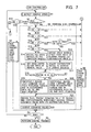
- Fig. 7 is a flowchart of an operation sequence of the car controller according to the embodiment of the present invention.
- the car controller 1 detects a vehicle speed VS (Step S1).
- a sequence for detecting the vehicle speed VS is shown by a flowchart shown in Fig. 4.
- the car controller 1 reads detected values V of the wheel speed sensors (SM) for a pair of two tandem-structured wheels (Step S30), and computes wheel angular-accelerations d ⁇ /dt (Step S31).
- the following expression can be used for computing a wheel angular-acceleration: d ⁇ /dt ⁇ (1/R) x dV/dt where R is a radius of a wheel, and V and ⁇ is respectively a wheel speed and a wheel angular-velocity of the wheel whose angular acceleration is to be computed.
- the car controller 1 compares the absolute values of the above-computed wheel angular-accelerations d ⁇ /dt of the foregoing one pair with a predetermined threshold. When the absolute values of the pair of two wheels (i.e., all two wheels) exceed the predetermined threshold, the car controller 1 determines that a slip (SL) occurs; when the absolute value of one of the pair of wheels exceeds the threshold and that of the other wheel does not exceed it, the car controller 1 determines that no slip (SX) occurs and also holds the wheel speed V of the other wheel as a wheel speed of the pair; and when the absolute values of the wheel angular-accelerations d ⁇ /dt of the pair of two wheels (i.e., all two wheels) do not exceed the predetermined threshold, the car controller 1 determines that no slip (SX) occurs and also holds the larger one of the wheel speeds as a wheel speed of the pair (Step S32).
- Step S33 When the car controller 1 determines that no slip (SX) occurs at the pair of wheels, the wheel speed V of the wheels is added to a variable VS (Step S33). Meanwhile, when the car controller 1 determines that a slip occurs at the pair of wheels, since it is considered that a slip occurs or is likely to occur because the absolute values of the angular accelerations d ⁇ /dt exceed the predetermined threshold, a variable NS for counting the number of pairs of wheels which are considered to slip or to be likely to slip (slipping wheels) is incremented by 1 (Step S34).
- Step S35 the car controller 1 stores the location and the wheel speed V of the pair of wheels in a memory or the like.
- the car controller 1 applies the sequence from Step S31 to S35 to all drive wheels including all tandem-structured wheels (Step S36).
- the car controller 1 determines whether the number NS of pairs of slipping wheels is equal to 4 or not, that is, whether all drive wheels slip or not (Step S37). Since all drive wheels do not usually slip or are likely to slip at the same time, the car controller 1 computes the vehicle speed VS by dividing the value VS accumulated in repeatedly carried out Step S33 by (4 - NS), that is, the number of pairs of non-slipping wheels (Step S38).
- Step S39 the car controller 1 searches which drive wheel has started lastly to slip by using the information stored when Step S35 was carried out.
- the car controller 1 sets the wheel speed V maintained by the drive wheel just before starting to slip, which was found by the above search, that is, which has started lastly to slip, as the vehicle speed VS (Step S40).
- the vehicle speed VS can be relatively accurately decided by computing the vehicle speed VS, in principle, only from the wheel speeds of non-slipping wheels, whereby a torque command value tentatively decided in a sequence, which will be mentioned later, becomes proper. Also, with the tandem suspension structure, all the eight wheels rarely slip or are almost unlikely to slip. Even when the above-mentioned state happens, since the average wheel speed maintained by the wheel, which has started lastly to slip, over a predetermined time period just before starting to slip is set as the vehicle speed VS, relatively reliable information can be used for tentatively deciding the torque command value.
- Step S38 or S40 the operation of the car controller 1 returns to Step S2 shown in Fig. 7.
- the car controller 1 upon detecting the vehicle speed VS, in order to assess the steering state, the car controller 1 first determines whether the absolute value of the steering angle ⁇ t is equal to or greater than a predetermined threshold or not (Step S2). When the steering angle exceeds the threshold and no slip occurs (Step S12), the car controller 1 performs a target-yaw-rate adaptive control or a target-slip-angle adaptive control (for example, a zero slip-angle control) (Step S3).
- a target-yaw-rate adaptive control or a target-slip-angle adaptive control for example, a zero slip-angle control
- the car controller 1 performs the target-yaw-rate adaptive control or the target-slip-angle adaptive control in order to prevent or suppress the driving instability of the vehicle caused by the steering.
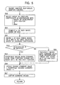
- FIG. 5 An example sequence of the target-yaw-rate adaptive control or the target-slip-angle adaptive control is shown in Fig. 5.
- the car controller 1 in accordance with an ON- or OFF-state of the accelerator determined on the basis of an output of the accelerator sensor 17, a shift position obtained by the shift position switch 16, a steering angle ⁇ t provided by the steering-angle sensor 15, d ⁇ t/dt which can be computed on the basis of the steering angle ⁇ t, and so forth, the car controller 1 first selects a group of coupling coefficients (by using an experimental expression) (Step S50).
- the car controller 1 computes a wheel acceleration dV/dt of each wheel forming the tandem suspension structure and then computes a coefficient of road friction ⁇ (by using another experimental expression) on the basis of the computed acceleration (Step S51).
- the car controller 1 decides a correction factor k of each wheel on the basis of the coefficient of road friction ⁇ and the steering angle ⁇ t and also by using the group of coupling coefficients selected in Step S50 (Step S52).
- Step S53 When the accelerator is in an ON-state (Step S53), the car controller 1 tentatively decides a torque command value of each wheel, from a powering torque map, on the basis of its wheel speed V, an accelerator opening VA, and the shift position (Step S54). Also, when the accelerator is in an OFF-state (Step S53), the car controller 1 tentatively decides a torque command value of each wheel, from a regenerating torque map, on the basis of its wheel speed V, the brake force FB, and the shift position (Step S55).
- the powering torque map shows a characteristic of the number of revolutions vs. torque where both the torque and the number of revolutions are positive
- the regenerating torque map shows a characteristic of the number of revolutions vs. torque where the number of revolutions is positive and the torque is negative.
- the car controller 1 decides a torque command value by multiplying the torque command value tentatively decided in Step S54, or S55 by the correction factor decided in Step S52 (Step S56) and outputs the decided torque command value to the corresponding motor controller (Step S57).
- a torque command value in a range possible for performing the target-yaw-rate adaptive control or the target-slip-angle adaptive control can be in a regenerating region even when the accelerator is in an ON-state or can be in a powering region even when the accelerator is in an OFF-state.
- Step S2 which is performed upon detecting the vehicle speed VS, when it is admitted that there is no need for performing the target-yaw-rate adaptive control or the target-slip-angle adaptive control, that is, when the absolute value of the steering angle is less than the threshold, in principle, the car controller 1 performs the sequence in association with an 8-WD control (Step S6).
- the car controller 1 When starting this 8-WD control Step S6, the car controller 1 first performs a determining and classifying process about the number NS of pairs of slipping wheels, each pair corresponding to one pair of slipping wheels forming the tandem suspension structure, detected in the sequence for detecting the vehicle speed VS.
- Step S7 when the number NS of pairs of the detected slipping wheels is equal to 4, that is, all the drive wheels slip or are likely to slip (Step S7) or when the number NS of pairs of the slipping wheels is 3, that is, when only one pair of the driving wheels forming the tandem suspension structure do not slip or are unlikely to slip (Step S8), the operation of the car controller 1 advances to a TRC/ABS equivalent control (Step S9), as opposed to advancing to the 8-WD control (Step S6).
- Step S9 the above operation advances to the TRC/ABS equivalent control (Step S9) when both pairs of the detected slipping wheels lie together at the left or at the right of the car (Step S11).
- Step S9 when the number NS of pairs of the slipping wheels is not zero, that is, when it is admitted that any one pair of the drive wheels forming the tandem suspension structure slip or are likely to slip.
- the car controller 1 In order to perform the TRC/ABS equivalent control, the car controller 1 first selects groups of coupling coefficients and control constants, and the like depending on whether the wheel speed V is high or low, whether the accelerator is in an ON-state or OFF-state, and so forth (Step S60).
- the groups of coupling coefficients and control constants mentioned above are respectively a group of coefficients used for deciding a group of thresholds used for determining an angular acceleration, which will be mentioned later, and a group of constants used for deciding a feedback torque.
- the car controller 1 tentatively decide a torque command value from the powering torque map in accordance with the wheel speed V, the accelerator opening VA and the shift position when it is determined in Step S61 that the accelerator is in an ON-state (Step S62) and from the regenerating torque map in accordance with the wheel speed V, the brake force FB and the shift position when it is determined in Step S61 that the accelerator is in an OFF-state (Step S63).
- the car controller 1 decides the group of thresholds, respectively, on the basis of the accelerator opening VA and the group of coupling coefficients selected in Step S60 (Step S64) or on the basis of the brake force FB and the group of coupling coefficients selected in Step S60 (Step S65).
- the car controller 1 classifies an angular acceleration d ⁇ /dt of each wheel relative to the group of thresholds decided in Step S64 or S65 (Step S66).
- the car controller 1 decides feedback torques by using different computing expressions or the like on the basis of the classified results. For example, when the angular acceleration d ⁇ /dt lies in a first, second, third, ---, or n-th range, the car controller 1 decides the feedback torque of each wheel by performing a feedback torque process with a first computing expression (Step S67-1), with a second computing expression (Step S67-2), with a third computing expression (Step S67-3), ---, or with a n-th computing expression (Step S67-n), respectively.
- Step S67-1, S67-2, S67-3, ---, S67-n are given by the group of control constants selected in Step 560.
- the car controller 1 decides torque command values by subtracting the corresponding feedback torques as decided above from the corresponding torque command values tentatively decided in Step S62 or S63 (Step S68) and outputs the decided torque command values to the corresponding motor controllers (Step S69).
- Step S6 When both the conditions for advancing to the target-yaw-rate adaptive control or the target-slip-angle adaptive control and to the TRC/ABS equivalent control are not satisfied, in other words, when the absolute value of the steering angle ⁇ t is less than the corresponding threshold; when the number NS of pairs of slipping wheels forming the tandem suspension structure is 2 or less; and when neither both wheels at the left nor those at the right of the car are slipping wheels, the car controller 1 performs the sequence of the 8-WD control (Step S6).
- the car controller 1 first determines whether the number NS of pairs of the foregoing slipping wheels is 1 or not (Step S13). Since the number NS is equal to zero when traveling on the normal road, the operation of the car controller 1 advances to Step S14 and S15.
- Step S14 the car controller 1 decides all drive wheels forming the tandem suspension structure as distribution wheels.
- the distribution wheel mentioned here means a drive wheel to which a torque output is actually distributed.
- step S15 the car controller 1 sets distribution ratios of a torque output to the corresponding distribution wheels at normal values. For example, a distribution ratio equal to 1 is set to all drive wheels.
- the foregoing distribution ratios may vary in accordance with a load of the car or may be set at predetermined ratios which are different between front and rear wheels in accordance with the structure of the vehicle.
- the car controller 1 decides wheels other than the pairs of slipping wheels as the distribution wheels (Step S16).
- the car controller 1 adjusts a distribution ratio of each wheel (Step S17).
- the distribution ratio of a pair of the drive wheels which are not selected as distribution wheels in Step S16 is adjusted to be zero so as to prevent the pair of wheels from being provided with torque command values, and the distribution ratio of the pair of non-slipping wheels lying at either one of the right and left sides where the pair of slipping wheels lie is added by the distribution ratio corresponding to the torque output which would otherwise be distributed to the pair of slipping wheels.
- the car controller 1 Upon performing Step S15 or S17, the car controller 1 tentatively decides a torque command value from the powering torque map in accordance with the vehicle speed VS, the accelerator opening VA, and the shift position when the accelerator is in an ON-state (Step S19) and from the regenerating torque map in accordance with the vehicle speed VS, the break force FB, and the shift position when the accelerator is in an OFF-state (Step S20).
- Step S19 or S20 the car controller 1 adjusts the torque command value of each pair of wheels tentatively decided in Step S19 or S20 in accordance with the corresponding distribution ratio previously set or adjusted in Step S15 or S17 (for example, multiplying the tentatively decided value by the distribution ratio) so as to decide a torque command value of the pair of wheels (Step S21).
- the car controller 1 outputs the torque command values decided in Step S21 to the corresponding motor controllers (Step S22), and then the operation thereof advances to Step S4.
- the control state of the car is changed over in accordance with the slipping state of each wheel forming the tandem suspension structure.
- two wheels forming the tandem suspension structure are regarded as one unit.
- the torque command value which would otherwise be output to these slipping wheels is output to the other drive wheels lying at the same side as the slipping wheels.
- the TRC/ABS equivalent control is performed.
- the TRC/ABS equivalent control is also performed.
- the car controller 1 changes over or varies a control mode of each motor output or a torque distribution ratio of each wheel in accordance with the occurrence condition of slipping or the slipping tendency of the wheel, in particular, with the number of units of slipping wheels and the locations thereof, the 8-WD control and the TRC/ABS equivalent control suitable for use in an 8 wheel-drive electric car of an in-wheel motor type are realized, and the running stability of the vehicle can be maintained and improved.
- the main electronic control unit Since the main electronic control unit is internally connected through the control-signal-use, alternative main transmission line CR as mentioned above, even when the transmission lines and the like malfunction, the electric control unit backs up the control system, thereby performing necessary controls as usual.
- a signal transmission system is formed by nodes (communication devices) installed at the car controller 1, the motor controllers 2, 3, 4, and 5, the battery controller A, the battery charging controller B, the brake controller C, and the steering controller 22, all forming the electronic control unit as shown in Fig. 3.
- the nodes (communication devices) are formed by a plurality of nodes N1, N2, N3, N4, N5, N10, N11, N12, and N13 respectively having self-node-ID storing means N1b, N2b, N3b, N4b, N5b, N10b, N11b N12b, and N13b for storing corresponding self-node identifiers N1, N2, N3, N4, N5, N10, N11, N12, and N13; adjacent-node-ID storing means N1c, N2c, N3c, N4c, N5c, N10c, N11c N12c, and N13c for storing identifiers of corresponding adjacent nodes connected to the corresponding transmission lines and
- the node which detected the communication failure sends a search message s including its self-identifier and the identifier of the adjacent node connected to the transmission lines on which the communication failure was detected; the node which received the search message compares the identifier ID of the adjacent node in the search message with identifiers stored in its self-node ID storing means and its adjacent node ID storing means; and, when all the above comparisons do not result in a coincidence with each other, the node which received the search message relays the search message to other nodes, and when any one of the above comparisons results in a coincidence with each other, the node which received the search message sends back a response message r for setting a bypass-route to the node which detected the communication failure.
- Data including a message type such as a search message or a response message, an identifier (ID) of a receiving communication device, an identifier (ID) of a sending communication device, an identifier (ID) of a malfunction-related communication device, and a remaining line capacity is written in a control section of a sending signal frame of the search message s or the response message r, respectively.
- the malfunction-related communication device means a malfunctioning communication device or an adjacent communication device connected to a malfunctioning transmission line.
- the node When each node detects that a transmission line between the node N1 of the car controller 1 and the node Nn of the corresponding motor controller is established, the node sets its own motor controller and inverter in a standby mode. Upon receiving a control command via the transmission lines, the motor controller controls the corresponding inverter in accordance with the control command.
- the node N2 detects that a communication failure occurs when no response comes from the opposing node.
- the processing means N2a of the node N2 sends data, which includes information that a message type is a search message s, an identifier of the sending communication device is N2, and an identifier of the malfunction-related communication device is N1 and which is written in a control section of the corresponding signal frame, to the node N13 or N3.
- bypass route described in the above-mentioned (a-2) can be set, while the bypass route described in the above-mentioned (a-1) cannot be set.
- the node N2 since there was no response to the polling in a predetermined time period, the node N2 detects the fact that the node N2 has lost all transmission lines to the car controller 1 due to the occurrences of the communication failures B1, B2, and B3, and hence changes the mode of the motor controller 2 from a standby mode to a stop mode so as to stop the inverters 10 and 10'.
- the car controller 1 detects the fact that there is no response from the node N2 in a predetermined time period, disconnects the node N2 from the transmission lines, and then controls the remaining motor controllers by backing up them via the remaining nodes.
- a bypass route between the car controller 1 and each of the controllers 2, 3, 4, 5, 10, 11, 12, and 13 is set in a similar fashion to that in the above mentioned embodiment.
- the present invention offers the following advantages.
- a control device of an electric car performs an accurate control between controllers fixed to corresponding electric motors, it is especially suitable as a control device of that which does not emit an exhaust gas affecting on global warming.
Landscapes
- Engineering & Computer Science (AREA)
- Power Engineering (AREA)
- Transportation (AREA)
- Mechanical Engineering (AREA)
- Life Sciences & Earth Sciences (AREA)
- Sustainable Development (AREA)
- Sustainable Energy (AREA)
- Physics & Mathematics (AREA)
- Electromagnetism (AREA)
- Electric Propulsion And Braking For Vehicles (AREA)
- Regulating Braking Force (AREA)
- Hybrid Electric Vehicles (AREA)
- Steering Control In Accordance With Driving Conditions (AREA)
Abstract
Description
Claims (13)
- A control device of an electric car including a plurality of driving wheels, each having a drive motor fixed thereto, comprising:a plurality of speed control devices, each fixed to the corresponding drive motor for accelerating or decelerating the corresponding driving wheel in accordance with an external electrical signal; and a main control device having functions of sending a control signal, to each of the speed control devices, for performing an acceleration or deceleration in accordance with a command from a driver or at least one of on-board sensors, and also receiving a control signal including information of an operating state of each of the drive motors and the speed control devices.
- The control device of an electric car according to Claim 1, wherein a voltage of a battery, a current fed from the battery, and a battery temperature are included as sensor signals which are input into the main control device.
- The control device of an electric car according to Claim 1, wherein a steering-angle of a steering wheel is included as a sensor signal which is input into the main control device.
- The control device of an electric car according to Claim 1, wherein a signal indicating that a battery is being recharged from a battery charger is included as a sensor signal which is input into the main control device.
- The control device of an electric car according to Claim 1, wherein signals representing a brake command value from a brake controller and a hydraulic pressure of a master cylinder are included as sensor signals which are input into the main control device.
- The control device of an electric car according to Claim 1, wherein a steering-angle signal of a steering wheel is included as a control signal sent from the main control device.
- A control device of an electric car, comprising fail safe means for signal transmission lines, wherein a bypass route is established such that a node detecting a communication failure in an electronic control system of the car sends a search message for searching a transmission route and another node which is able to establish the transmission route sends back a response message.
- The control device of an electric car according to Claim 7, wherein each of the nodes comprises self-node-ID storing means for storing its own node identifier, adjacent-node-ID storing means for storing identifiers of adjacent nodes connected to the transmission route, and processing means for processing route setting on the basis of a message sent to the node.
- The control device of an electric car according to Claim 8, wherein the node is provided at each of a car controller and motor controllers, each provided at a pair of wheels.
- The control device of an electric car according to Claim 8, wherein the node is provided at each of a battery controller, a steering controller, a brake controller, and a battery charging controller.
- The control device of an electric car according to Claim 9, wherein the car controller and the motor controllers, each provided at a pair of wheels, control corresponding power converters in accordance with control signals received via the corresponding nodes.
- The control device of an electric car according to Claim 9 or 10, wherein the bypass route is established by a control-signal-use, alternative main transmission line forming a closed loop and alternative transmission lines connecting the alternative main transmission line and the motor controllers.
- The control device of an electric car according to Claim 12, wherein, when a certain node detects that all communication lines and bypass routes to the car controller malfunction, the node stops an operation of the corresponding motor controller, and the car controller detects that there is no response from the certain node and separates the motor controller of the certain node from its control objects.
Applications Claiming Priority (3)
| Application Number | Priority Date | Filing Date | Title |
|---|---|---|---|
| JP2000384089A JP3476770B2 (en) | 2000-12-18 | 2000-12-18 | Electric vehicle control device |
| JP2000384089 | 2000-12-18 | ||
| PCT/JP2001/009420 WO2002049871A1 (en) | 2000-12-18 | 2001-10-26 | Controller for electric automobile |
Publications (2)
| Publication Number | Publication Date |
|---|---|
| EP1344676A1 true EP1344676A1 (en) | 2003-09-17 |
| EP1344676A4 EP1344676A4 (en) | 2012-02-22 |
Family
ID=18851629
Family Applications (1)
| Application Number | Title | Priority Date | Filing Date |
|---|---|---|---|
| EP01980916A Withdrawn EP1344676A4 (en) | 2000-12-18 | 2001-10-26 | CONTROL UNIT FOR ELECTRIC MOTOR VEHICLE |
Country Status (4)
| Country | Link |
|---|---|
| US (2) | US6909950B2 (en) |
| EP (1) | EP1344676A4 (en) |
| JP (1) | JP3476770B2 (en) |
| WO (1) | WO2002049871A1 (en) |
Cited By (3)
| Publication number | Priority date | Publication date | Assignee | Title |
|---|---|---|---|---|
| EP2660953A3 (en) * | 2006-07-13 | 2016-04-13 | Protean Electric Limited | Electric motors |
| EP3203627A4 (en) * | 2014-10-01 | 2018-05-16 | Hitachi Industrial Equipment Systems Co., Ltd. | Power conversion device, power conversion method, and power conversion system |
| EP2808454B1 (en) * | 2013-05-30 | 2022-03-30 | Kobelco Construction Machinery Co., Ltd. | Motor Controller and Construction Machine Provided Therewith |
Families Citing this family (42)
| Publication number | Priority date | Publication date | Assignee | Title |
|---|---|---|---|---|
| JP3476770B2 (en) * | 2000-12-18 | 2003-12-10 | 科学技術振興事業団 | Electric vehicle control device |
| DE10297133B4 (en) * | 2001-08-23 | 2013-05-08 | General Motors Corp. | Chassis of a vehicle with systems that respond to non-mechanical control signals |
| US20050127856A1 (en) * | 2002-07-31 | 2005-06-16 | Wavecrest Laboratories | Low-voltage electric motors |
| US7653526B1 (en) * | 2002-08-16 | 2010-01-26 | Cisco Technology, Inc. | Method and system for emulating an ethernet link over a sonet path |
| DE60327260D1 (en) * | 2003-02-11 | 2009-05-28 | Nexter Systems | METHOD FOR REDUCING THE SPEED OF A VEHICLE IN CURVES |
| JP4325284B2 (en) * | 2003-06-04 | 2009-09-02 | トヨタ自動車株式会社 | Voltage converter |
| JP3948453B2 (en) * | 2003-11-18 | 2007-07-25 | 日産自動車株式会社 | Vehicle driving force control device |
| JP2005289324A (en) * | 2004-04-05 | 2005-10-20 | Bridgestone Corp | Vehicle with rear wheel auxiliary drive motor |
| JP4483522B2 (en) | 2004-10-22 | 2010-06-16 | 株式会社ジェイテクト | Electric power steering apparatus and power supply system |
| US7953536B2 (en) * | 2005-07-29 | 2011-05-31 | GM Global Technology Operations LLC | Inertial sensor software architecture security method |
| DE102005046373B4 (en) * | 2005-09-28 | 2007-12-13 | Siemens Ag | Communication system for a technical device, in particular for a motor vehicle |
| KR20080081331A (en) * | 2005-12-22 | 2008-09-09 | 코닌클리즈케 필립스 일렉트로닉스 엔.브이. | Submounts, submount manufacturing methods, use of submounts, and light emitting devices |
| IL174061A0 (en) * | 2006-03-02 | 2006-08-01 | Amihud Rabin | Safety control system for electric vehicle |
| US20070222287A1 (en) * | 2006-03-22 | 2007-09-27 | Ford Global Technologies, Llc | Automotive regenerative and friction braking system and control method |
| JP4770538B2 (en) | 2006-03-24 | 2011-09-14 | 株式会社日立製作所 | Electric drive vehicle and control method of electric drive vehicle |
| JP2008137608A (en) * | 2006-12-05 | 2008-06-19 | Toyota Motor Corp | Vehicle speed estimation device, vehicle speed estimation method, and braking / driving force control device |
| JP4459247B2 (en) * | 2007-03-26 | 2010-04-28 | 三菱電機株式会社 | Wheel independent drive vehicle control device |
| DE102007050773A1 (en) * | 2007-10-24 | 2009-04-30 | Zf Friedrichshafen Ag | Automobile control system |
| DE102007050771A1 (en) * | 2007-10-24 | 2009-05-07 | Zf Friedrichshafen Ag | Automobile control system |
| DE102007050775A1 (en) * | 2007-10-24 | 2009-04-30 | Zf Friedrichshafen Ag | Automobile control system |
| KR100970093B1 (en) * | 2008-08-29 | 2010-07-16 | 성균관대학교산학협력단 | Sensor network control method for data path establishment and recovery and sensor network system for same |
| US10189359B2 (en) * | 2009-02-17 | 2019-01-29 | Chargepoint, Inc. | Transmitting notification messages for an electric vehicle charging network |
| US8442690B2 (en) * | 2009-06-29 | 2013-05-14 | Honeywell International Inc. | Vehicle system monitoring and communications architecture |
| US20110168466A1 (en) * | 2010-01-14 | 2011-07-14 | Gary Starr | Hub wheel motor |
| US20110168465A1 (en) * | 2010-01-14 | 2011-07-14 | Gary Starr | Hub wheel motor |
| US8521349B2 (en) | 2010-06-10 | 2013-08-27 | Ford Global Technologies | Vehicle steerability and stability control via independent wheel torque control |
| KR101360038B1 (en) * | 2011-07-28 | 2014-02-07 | 현대자동차주식회사 | Control method of vehicle using in-wheel motor |
| EP2783906B1 (en) * | 2011-11-24 | 2019-09-04 | NTN Corporation | Electric vehicle control device |
| JP5994607B2 (en) * | 2012-11-29 | 2016-09-21 | トヨタ自動車株式会社 | Coaxial two-wheel moving body and control method thereof |
| US20150114739A1 (en) * | 2013-10-31 | 2015-04-30 | Curtis Arnold Newman | Hydraulic Hybrid Vehicle |
| JP6236674B2 (en) * | 2014-02-21 | 2017-11-29 | 日立オートモティブシステムズ株式会社 | Electric vehicle control system |
| US9380070B1 (en) * | 2015-01-20 | 2016-06-28 | Cisco Technology, Inc. | Intrusion detection mechanism |
| JP6973151B2 (en) * | 2018-02-14 | 2021-11-24 | トヨタ自動車株式会社 | Motor control device |
| US20190344764A1 (en) * | 2018-05-14 | 2019-11-14 | Westinghouse Air Brake Technologies Corporation | Distributed Brake Retention and Control System for a Train and Associated Methods |
| JP7263788B2 (en) * | 2019-01-17 | 2023-04-25 | 株式会社デンソー | Control device |
| JP7327147B2 (en) * | 2019-12-19 | 2023-08-16 | トヨタ自動車株式会社 | vehicle |
| JP7276114B2 (en) | 2019-12-19 | 2023-05-18 | トヨタ自動車株式会社 | vehicle |
| JP7327146B2 (en) * | 2019-12-19 | 2023-08-16 | トヨタ自動車株式会社 | VEHICLE, VEHICLE CONTROL SYSTEM AND VEHICLE CONTROL METHOD |
| KR20240012583A (en) | 2021-06-30 | 2024-01-29 | 레겟 앤드 플랫 캐나다 코포레이션 | Smart motor systems and methods using local intelligence |
| US12222738B2 (en) * | 2022-02-01 | 2025-02-11 | Ford Global Technologies, Llc | Method and system for controlling electric drive system according to predicted temperature of DC-link capacitor to prevent overheating |
| US12267989B2 (en) | 2022-02-10 | 2025-04-01 | Ford Global Technologies, Llc | Method and system for controlling electric drive system according to predicted temperature of inverter busbar |
| EP4681395A1 (en) * | 2023-04-04 | 2026-01-21 | Amphion Technology, LLC | Vehicle mobility system communications network |
Family Cites Families (25)
| Publication number | Priority date | Publication date | Assignee | Title |
|---|---|---|---|---|
| US4451054A (en) * | 1982-05-11 | 1984-05-29 | Allison William D | Vehicle suspension system |
| JP2672310B2 (en) | 1987-12-19 | 1997-11-05 | アイシン・エィ・ダブリュ株式会社 | Vehicle network communication controller |
| JPH01164204A (en) | 1987-12-19 | 1989-06-28 | Aisin Aw Co Ltd | Vehicle control network system |
| JP2834808B2 (en) * | 1989-12-08 | 1998-12-14 | 三菱電機株式会社 | Automotive control device |
| CA2133318A1 (en) * | 1992-04-28 | 1993-11-11 | Christopher John Glenn | Control means for electrically driven vehicules |
| US5941925A (en) * | 1992-11-26 | 1999-08-24 | Robert Bosch Gmbh | Method and arrangement for controlling a motor vehicle |
| JPH06236352A (en) * | 1993-02-09 | 1994-08-23 | Nippondenso Co Ltd | Data communication device |
| KR0141893B1 (en) * | 1993-06-30 | 1998-06-01 | 나까무라 유이찌 | Fault diagnosis apparatus and method for vehicle control system |
| DE19600644C1 (en) * | 1996-01-10 | 1997-04-24 | Bosch Gmbh Robert | Automobile function module circuit |
| US6434459B2 (en) * | 1996-12-16 | 2002-08-13 | Microsoft Corporation | Automobile information system |
| DE19714937A1 (en) * | 1997-04-10 | 1998-10-15 | Bayerische Motoren Werke Ag | Data bus system for motor vehicles |
| US6480510B1 (en) * | 1998-07-28 | 2002-11-12 | Serconet Ltd. | Local area network of serial intelligent cells |
| US6115580A (en) * | 1998-09-08 | 2000-09-05 | Motorola, Inc. | Communications network having adaptive network link optimization using wireless terrain awareness and method for use therein |
| AU758135B2 (en) * | 1998-10-21 | 2003-03-13 | Deka Products Limited Partnership | Fault tolerant architecture for a personal vehicle |
| JP4162782B2 (en) * | 1998-11-19 | 2008-10-08 | 富士重工業株式会社 | Control device for hybrid vehicle |
| DE69940571D1 (en) | 1998-12-03 | 2009-04-23 | Agency Ind Science Techn | Communication method and system |
| JP3844904B2 (en) * | 1999-03-31 | 2006-11-15 | 三菱電機株式会社 | Vehicle control communication system |
| US7006902B2 (en) * | 1999-07-30 | 2006-02-28 | Oshkosh Truck Corporation | Control system and method for an equipment service vehicle |
| US6687585B1 (en) * | 2000-11-09 | 2004-02-03 | The Ohio State University | Fault detection and isolation system and method |
| US6766230B1 (en) * | 2000-11-09 | 2004-07-20 | The Ohio State University | Model-based fault detection and isolation system and method |
| US6863149B2 (en) * | 2000-12-12 | 2005-03-08 | Japan Science And Technology Corporation | Steering mechanism of electric car |
| JP3476770B2 (en) * | 2000-12-18 | 2003-12-10 | 科学技術振興事業団 | Electric vehicle control device |
| US6622804B2 (en) * | 2001-01-19 | 2003-09-23 | Transportation Techniques, Llc. | Hybrid electric vehicle and method of selectively operating the hybrid electric vehicle |
| US6816764B2 (en) * | 2002-05-02 | 2004-11-09 | Ford Global Technologies, Llc | Suspension coordinator subsystem and method |
| JP4024597B2 (en) * | 2002-06-11 | 2007-12-19 | 独立行政法人科学技術振興機構 | Electric vehicle body structure |
-
2000
- 2000-12-18 JP JP2000384089A patent/JP3476770B2/en not_active Expired - Fee Related
-
2001
- 2001-10-26 EP EP01980916A patent/EP1344676A4/en not_active Withdrawn
- 2001-10-26 US US10/450,254 patent/US6909950B2/en not_active Expired - Fee Related
- 2001-10-26 WO PCT/JP2001/009420 patent/WO2002049871A1/en not_active Ceased
-
2005
- 2005-05-12 US US11/127,266 patent/US7072751B2/en not_active Expired - Fee Related
Cited By (3)
| Publication number | Priority date | Publication date | Assignee | Title |
|---|---|---|---|---|
| EP2660953A3 (en) * | 2006-07-13 | 2016-04-13 | Protean Electric Limited | Electric motors |
| EP2808454B1 (en) * | 2013-05-30 | 2022-03-30 | Kobelco Construction Machinery Co., Ltd. | Motor Controller and Construction Machine Provided Therewith |
| EP3203627A4 (en) * | 2014-10-01 | 2018-05-16 | Hitachi Industrial Equipment Systems Co., Ltd. | Power conversion device, power conversion method, and power conversion system |
Also Published As
| Publication number | Publication date |
|---|---|
| JP3476770B2 (en) | 2003-12-10 |
| US20050206332A1 (en) | 2005-09-22 |
| JP2002186120A (en) | 2002-06-28 |
| EP1344676A4 (en) | 2012-02-22 |
| US7072751B2 (en) | 2006-07-04 |
| US20040027076A1 (en) | 2004-02-12 |
| US6909950B2 (en) | 2005-06-21 |
| WO2002049871A1 (en) | 2002-06-27 |
Similar Documents
| Publication | Publication Date | Title |
|---|---|---|
| US6909950B2 (en) | Controller for electric automobile | |
| US6930405B2 (en) | Vehicle control apparatus | |
| CN115071738A (en) | Intelligent vehicle and control logic for managing failure of dual independent drive unit axle powertrain | |
| CN113226830B (en) | Trailer and trailer brake controller and method and computer program product thereof | |
| JP4306746B2 (en) | Vehicle power supply | |
| CN107791885B (en) | Fail-safe apparatus of ECM system and method thereof | |
| US9573466B2 (en) | Vehicle, and vehicle control method | |
| US6958587B1 (en) | Torque distribution for multiple propulsion system vehicles | |
| JPH11164402A (en) | Controller and controlling method for hybrid vehicle | |
| CN110816281B (en) | Control unit, device and method for vehicle regenerative braking control | |
| JP5316576B2 (en) | Vehicle control device | |
| JP2009518225A (en) | Method and apparatus for controlling and monitoring a hybrid vehicle of the type including four drive wheels | |
| KR20160040629A (en) | Vehicle | |
| JP4186723B2 (en) | Energy management apparatus and energy management method | |
| JP3611390B2 (en) | Control device for electric vehicle | |
| JP2017019399A (en) | Hybrid-vehicle control apparatus | |
| JP2003209905A (en) | Hybrid vehicle control device | |
| JP3370983B2 (en) | Drive control device for electric vehicle | |
| JP5060076B2 (en) | Control method of engine in vehicle | |
| JP2004237886A (en) | Braking control device | |
| US11091147B2 (en) | Motor system and control method for motor system | |
| US20220144246A1 (en) | Control device, control method, and electrical vehicle | |
| JP2006136177A (en) | Vehicle motor traction control device | |
| JP2002010404A (en) | Vehicle control device | |
| WO2002060717A1 (en) | Power supply for electric automobile |
Legal Events
| Date | Code | Title | Description |
|---|---|---|---|
| PUAI | Public reference made under article 153(3) epc to a published international application that has entered the european phase |
Free format text: ORIGINAL CODE: 0009012 |
|
| 17P | Request for examination filed |
Effective date: 20030617 |
|
| AK | Designated contracting states |
Kind code of ref document: A1 Designated state(s): AT BE CH CY DE DK ES FI FR GB GR IE IT LI LU MC NL PT SE TR |
|
| RBV | Designated contracting states (corrected) |
Designated state(s): DE FR IT |
|
| RAP1 | Party data changed (applicant data changed or rights of an application transferred) |
Owner name: JAPAN SCIENCE AND TECHNOLOGY AGENCY |
|
| RAP1 | Party data changed (applicant data changed or rights of an application transferred) |
Owner name: JAPAN SCIENCE AND TECHNOLOGY AGENCY |
|
| A4 | Supplementary search report drawn up and despatched |
Effective date: 20120119 |
|
| RIC1 | Information provided on ipc code assigned before grant |
Ipc: B60L 15/20 20060101AFI20120113BHEP |
|
| 17Q | First examination report despatched |
Effective date: 20120514 |
|
| STAA | Information on the status of an ep patent application or granted ep patent |
Free format text: STATUS: THE APPLICATION IS DEEMED TO BE WITHDRAWN |
|
| 18D | Application deemed to be withdrawn |
Effective date: 20150501 |