EP1344614A1 - Leg structure of legged robot - Google Patents
Leg structure of legged robot Download PDFInfo
- Publication number
- EP1344614A1 EP1344614A1 EP01982829A EP01982829A EP1344614A1 EP 1344614 A1 EP1344614 A1 EP 1344614A1 EP 01982829 A EP01982829 A EP 01982829A EP 01982829 A EP01982829 A EP 01982829A EP 1344614 A1 EP1344614 A1 EP 1344614A1
- Authority
- EP
- European Patent Office
- Prior art keywords
- roll
- pitch
- shaft
- foot part
- lower leg
- Prior art date
- Legal status (The legal status is an assumption and is not a legal conclusion. Google has not performed a legal analysis and makes no representation as to the accuracy of the status listed.)
- Granted
Links
Images



Classifications
-
- B—PERFORMING OPERATIONS; TRANSPORTING
- B25—HAND TOOLS; PORTABLE POWER-DRIVEN TOOLS; MANIPULATORS
- B25J—MANIPULATORS; CHAMBERS PROVIDED WITH MANIPULATION DEVICES
- B25J5/00—Manipulators mounted on wheels or on carriages
-
- B—PERFORMING OPERATIONS; TRANSPORTING
- B25—HAND TOOLS; PORTABLE POWER-DRIVEN TOOLS; MANIPULATORS
- B25J—MANIPULATORS; CHAMBERS PROVIDED WITH MANIPULATION DEVICES
- B25J13/00—Controls for manipulators
- B25J13/08—Controls for manipulators by means of sensing devices, e.g. viewing or touching devices
- B25J13/085—Force or torque sensors
-
- B—PERFORMING OPERATIONS; TRANSPORTING
- B25—HAND TOOLS; PORTABLE POWER-DRIVEN TOOLS; MANIPULATORS
- B25J—MANIPULATORS; CHAMBERS PROVIDED WITH MANIPULATION DEVICES
- B25J17/00—Joints
- B25J17/02—Wrist joints
- B25J17/0258—Two-dimensional joints
- B25J17/0275—Universal joints, e.g. Hooke, Cardan, ball joints
Definitions
- the present invention relates to a legged mobile robot leg structure and, in particular, a legged mobile robot leg structure in which a lower leg part is connected through a knee joint to the lower end of an upper leg part, a foot part is connected through an ankle joint to the lower end of the lower leg part, and the ankle joint supports the foot part such that the foot part can pitch and roll relative to the lower leg part.
- Such a legged mobile robot leg structure is known from Japanese Patent Application Laid-open No. 3-184782.
- a pitch motor is provided at a position close to the upper end of a lower leg part, and makes a foot part pitch relative to the lower leg part around a pitch shaft via a belt transfer means, and a roll motor is provided on a roll shaft that is perpendicular to the pitch shaft, and makes the foot part roll relative to the lower leg part.
- a six-axis force sensor for controlling bipedal walking of the robot is mounted on the foot part, and if the roll motor is provided in a lower part of the lower leg part at a position close to the foot part, then it is necessary to take special measures to alleviate the influence of noise of the roll motor, which is also a problem.
- the roll motor is provided in the vicinity of an ankle joint, the position of the ankle joint is raised from a floor surface, the amount of compliance control of the ankle joint is large, and it is therefore difficult to rapidly respond to unexpected unevenness and inclination of the floor surface, which is also a problem.
- the present invention has been achieved in view of these circumstances, and an object thereof is to reduce the driving force for driving a lower leg part by decreasing the moment of inertia around a knee joint and, at the same time, minimize the influence of the noise of a motor on a sensor provided on a foot part, and another object thereof is to rapidly respond to unexpected unevenness and inclination of a floor surface by lowering the height of an ankle joint from the floor surface.
- a legged mobile robot leg structure in which a lower leg part is connected to the lower end of an upper leg part through a knee joint, a foot part is connected to the lower end of the lower leg part through an ankle joint, and the ankle joint supports the foot part so that the foot part can pitch around a lateral axis and roll around a fore-and-aft axis relative to the lower leg part, the legged mobile robot leg structure including a pitch motor for making the foot part pitch around the lateral axis, the pitch motor being supported on the lower leg part at a position above the ankle joint, and a roll motor for making the foot part roll around the fore-and-aft axis, the roll motor being supported on the lower leg part at a position above the ankle joint.
- the pitch motor for making the foot part pitch around the lateral axis and the roll motor for making the foot part roll around the fore-and-aft axis are supported on the lower leg part at positions above the ankle joint, the positions of the pitch motor and the roll motor, which are heavy, are close to the knee joint, and as a result, the moment of inertia of the lower leg part around the knee joint can be decreased, thereby reducing the load imposed on the drive source for driving the knee joint.
- a legged mobile robot leg structure that includes a pitch shaft supported on the lower leg part such that the pitch shaft can rotate around the lateral axis, a pitch belt transfer means for transferring rotation of an output shaft of the pitch motor to the pitch shaft, the output shaft being disposed in the direction of the lateral axis, and a roll mechanism for rollably supporting the foot part on the pitch shaft.
- the pitch shaft is driven via the pitch belt transfer means for transferring the rotation of the output shaft of the pitch motor to the pitch shaft, rotating the pitch shaft can make the roll mechanism and the foot part pitch as a unit, and operating the roll mechanism can make the foot part roll relative to the pitch shaft, thereby preventing pitching and rolling of the foot part from interfering with each other.
- a legged mobile robot leg structure in which a lower leg part is connected to the lower end of an upper leg part through a knee joint, a foot part is connected to the lower end of the lower leg part through an ankle joint, and the ankle joint supports the foot part so that the foot part can pitch around a lateral axis and roll around a fore-and-aft axis relative to the lower leg part
- the legged mobile robot leg structure including a pitch shaft and a roll shaft that are fixed so as to be perpendicular to each other and that rotate around the lateral axis and the fore-and-aft axis respectively, a rotating member that is rotatably supported on the outer periphery of one of the pitch shaft and the roll shaft and that rotates integrally with the foot part, a first drive source that rotates the other one of the pitch shaft and the roll shaft, a drive bevel gear coaxially disposed within said other one of the pitch shaft and the roll shaft
- the rotating member integral with the foot part is rotatably supported on the outer periphery of one of the pitch shaft and the roll shaft that are fixed so as to be perpendicular to each other, the drive bevel gear coaxialty disposed within the other one of the pitch shaft and the roll shaft meshes with the driven bevel gear coaxially disposed within said one of the pitch shaft and the roll shaft and connected to the rotating member, said other one of the pitch shaft and the roll shaft is rotated by the first drive source, and the drive bevel gear is rotated by the second drive source, pitching and rolling of the foot part can be carried out independently without interfering with each other. Moreover, since the positions of the pitch shaft and the roll shaft can be lowered, compliance control of the ankle joint can be achieved with a smaller amount of control, thereby enabling stable walking by rapidly responding to unexpected unevenness and inclination of the floor surface.
- a legged mobile robot leg structure in which a lower leg part is connected to the lower end of an upper leg part through a knee joint, a foot part is connected to the lower end of the lower leg part through an ankle joint, and the ankle joint supports the foot part so that the foot part can pitch around a lateral axis and roll around a fore-and-aft axis relative to the lower leg part
- the legged mobile robot leg structure including a roll mechanism for rollably supporting the foot part on a pitch shaft, the roll mechanism including a roll shaft fixed to the pitch shaft so as to be perpendicular thereto, a roll member integrally fixed to the foot part and rotatably supported on the outer periphery of the roll shaft, a drive bevel gear coaxially disposed within the pitch shaft, a roll belt transfer means for transferring rotation of an output shaft of a roll motor to the drive bevel gear, the output shaft being disposed in the direction of the lateral axis, and
- the roll member integrally having the foot part is rotatably supported on the outer periphery of the roll shaft that is fixed so as to be perpendicular to the pitch shaft, and the rotation of the output shaft of the roll motor is transferred to the roll member via the roll belt transfer means, the drive bevel gear coaxially disposed within the pitch shaft, and the driven bevel gear coaxially disposed within the roll shaft, the foot part can be made to roll independently without interfering with pitching of the foot part, and the foot part can be freely made to pitch while the foot part is rolling. Moreover, since the positions of the pitch shaft and the roll shaft can be lowered, compliance control of the ankle joint can be achieved with a smaller amount of control, thereby enabling stable walking by rapidly responding to unexpected unevenness and inclination of the floor surface.
- a legged mobile robot leg structure wherein a pitch reduction gear is disposed between a pitch belt transfer means and the pitch shaft, and a roll reduction gear is disposed between the driven bevel gear and the roll member.
- the pitch reduction gear is disposed between the pitch belt transfer means and the pitch shaft, the load imposed on a pitch motor can be reduced, and since the roll reduction gear is disposed between the driven bevel gear and the roll member, the load imposed on the roll motor can be reduced.
- a legged mobile robot leg structure wherein the outside of the roll member is covered by a partially spherical cover, and a predetermined gap is formed between the partially spherical cover and the lower end of a skeleton-forming lower leg link of the lower leg part.
- a legged mobile robot leg structure in addition to the arrangement of the sixth aspect, there is proposed a legged mobile robot leg structure, wherein the partially spherical cover has the center thereof on the pitch shaft or the roll shaft.
- the partially spherical cover since the partially spherical cover has its center on the pitch shaft or the roll shaft, the gap that is formed between the partially spherical cover and the lower leg link when the foot part pitches or rolls is kept constant and the partially spherical cover is prevented from interfering with the lower leg link, thus increasing the movable range of the ankle joint while further effectively preventing foreign object from being trapped.
- a legged mobile robot leg structure wherein a sensor for detecting a load imposed on the foot part is provided on the foot part.
- the sensor provided on the foot part is less affected by the noise of the motors, thereby improving detection accuracy.
- a pitch motor 34 and a roll motor 35 in an embodiment form respectively the first drive source and the second drive source of the present invention; a roll member 46 of the embodiment forms the rotating member of the present invention; an inner partially spherical cover 62 and an outer partially spherical cover 63 of the embodiment form the partially spherical cover of the present invention; and a six-axis force sensor 60 of the embodiment forms the sensor of the present invention.
- an independent, bipedal walking legged mobile robot R includes a body 11, a head 12, a left arm 13L, a right arm 13R, a left leg 14L, and a right leg 14R, and carries on the back of the body 11 an electrical equipment box 15 housing electrical equipment.
- Each of the left arm 13L and the right arm 13R is formed form an upper arm part 16, a lower arm part 17, and a hand part 18; the body 11 and the upper arm part 16 are connected together through a shoulder joint 19; the upper arm part 16 and the lower arm part 17 are connected together through an elbow joint 20; the lower arm part 17 and the hand part 18 are connected together through a wrist joint 21; and an upper arm joint 22 is further provided in a longitudinally middle section of the upper arm part 16 for twisting a lower half of the upper arm part 16 relative to an upper half thereof.
- each of the left leg 14L and the right leg 14R is formed from an upper leg part 23, a lower leg part 24, and a foot part 25; the body 11 and the upper leg part 23 are connected together through a hip joint 26; the upper leg part 23 and the lower leg part 24 are connected together through a knee joint 27; and the lower leg part 24 and the foot part 25 are connected together through an ankle joint 28. Furthermore, the body 11 and the head 12 are connected together through a neck joint 29. Only the positions of the above-mentioned joints are shown by broken circles.
- the upper leg part 23 and the lower leg part 24 are connected together through the knee joint 27 having an axis L and are driven by a drive source (not illustrated) via a belt transmission means 31 and a reduction gear 32.
- the lower leg part 24 includes a skeleton-forming lower leg link 33, a pitch motor 34 is supported in an upper end part of the lower leg link 33 so that an output shaft 34a of the pitch motor 34 is disposed in the direction of a lateral axis Ly, and a roll motor 35 is supported in a middle part of the lower leg link 33 so that an output shaft 35a of the roll motor 35 is disposed in the direction of the lateral axis Ly.
- a pitch shaft 36 is rotatably supported on the lower end of the lower leg link 33 via a pair of cross roller bearings 38 and 38 on the lateral axis Ly (see FIG. 3).
- a drive pulley 39 provided on the output shaft 34a of the pitch motor 34 and a driven pulley 40 disposed on the lateral axis Ly are connected together via an endless belt 41.
- the drive pulley 39, the driven pulley 40, and the endless belt 41 form a pitch belt transfer means 42.
- the driven pulley 40 and the pitch shaft 36 are connected together via a pitch reduction gear 43, which is formed of a known harmonic decelerator (product name).
- the harmonic decelerator reduces the speed of rotation of an input member and outputs it to a coaxially disposed output member, and can be replaced with a planetary gear type reduction gear.
- a roll shaft 44 Formed integrally on the pitch shaft 36 is a roll shaft 44 extending in a direction (fore-and-aft axis Lx) perpendicular to the pitch shaft 36 (see FIG. 4).
- a tubular roll member 46 is support on the outer periphery of the roll shaft 44 via a pair of cross roller bearings 47 and 47, and the foot part 25 is fixed to this roll member 46.
- a driven pulley 52 is fixed to one shaft end of a drive bevel gear shaft 51 that is relatively rotatably supported within the pitch shaft 36.
- a drive pulley 53 is fixed to the output shaft 35a of the roll motor 35 and is connected to the driven pulley 52 via an endless belt 54.
- the drive pulley 53, the driven pulley 52, and the endless belt 54 form a roll belt transfer means 55.
- a driven bevel gear shaft 56 is relatively rotatably supported within the roll shaft 44, which is formed integrally with the pitch shaft 36.
- a driven bevel gear 57 is provided on one shaft end of the driven bevel gear shaft 56 and meshes with a drive bevel gear 58 that is provided on the other shaft end of the drive bevel gear shaft 51.
- a roll reduction gear 59 which is formed of a harmonic reduction gear.
- a six-axis force sensor 60 for detecting 6 component forces (loads in three orthogonal axial directions and moments around the three axes) that act on the foot part 25.
- an amplifier 64 for the six-axis force sensor 60.
- a roll mechanism 61 for making the foot part 25 roll relative to the pitch shaft 36 is formed from the roll shaft 44, the roll member 46, the drive bevel gear shaft 51, the drive bevel gear 58, the driven bevel gear shaft 56, the driven bevel gear 57, and the roll belt transfer means 55.
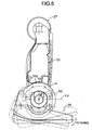
- the ankle joint 28 that supports the foot part 25 so that it can pitch and roll relative to the lower leg part 24 includes an inner, partially spherical cover 62 and an outer, partially spherical cover 63 that form a part of concentric spherical surfaces having their centers at the point of intersection of the fore-and-aft axis Lx and the lateral axis Ly.
- the inner, partially spherical cover 62 is fixed to the roll member 46, whereas the outer, partially spherical cover 63 is fixed to the pitch shaft 36.
- a concave spherical surface 33a is formed on the lower end of the lower leg link 33, and a minute and uniform gap ⁇ is formed between this concave spherical surface 33a and the outer peripheral surfaces of the outer, partially spherical cover 63 and the inner, partially spherical cover 62.
- the pitch motor 34 and the roll motor 35 are supported on the lower leg part 24 at positions above the ankle joint 28, the positions of the pitch motor 34 and the roll motor 35, which are heavy, are close to the knee joint 27. As a result, the moment of inertia of the lower leg part 24 around the knee joint 27 can be decreased, and the load imposed on the drive source for driving the knee joint 27 can be reduced. Moreover, since the positions of the pitch motor 34 and the roll motor 35 are far from the six-axis force sensor 60 provided on the foot part 25, the six-axis force sensor 60 is less affected by noise of the pitch motor 34 and the roll motor 35, thereby improving detection accuracy.
- this arrangement of the pitch motor 34 and the roll motor 35 can lower the positions of the pitch shaft 36 and the roll shaft 44, thereby achieving compliance control of the ankle joint 28 with a smaller amount of control. This enables stable walking by rapidly responding to unexpected unevenness and inclination of a floor surface.
- the gap ⁇ between the two covers 62, 63 and the concave spherical surface 33a of the lower end of the lower leg link 33 can be kept constant, thereby preventing foreign object from being trapped.
- the inner, partially spherical cover 62 rotates relative to the outer, partially spherical cover 63, but the gap ⁇ does not change, thereby also preventing foreign object from being trapped.
- the gap ⁇ does not change, the inner, partially spherical cover 62 and the outer, partially spherical cover 63 are less likely to interfere with the lower leg link 33, thereby increasing the movable range of the ankle joint 28.
- the roll member 46 to which the foot part 25 is integrally fixed is rotatably supported on the outer periphery of the roll shaft 44, the drive bevel gear 58 coaxially disposed within the pitch shaft 36 meshes with the driven bevel gear 57 coaxially disposed within the roll shaft 44 and connected to the roll member 46, and the foot part 25 is made to pitch by rotating the pitch shaft 36 by means of the pitch motor 34, and is made to roll by rotating the drive bevel gear 58 by means of the roll motor 35.
- a pitch member (corresponding to the rotating member of Claim 3 of the present invention), to which a foot part 25 is integrally fixed, on the outer periphery of a pitch shaft 36, make a drive bevel gear 58 coaxially disposed within a roll shaft 44 mesh with a driven bevel gear 57 coaxially disposed within the pitch shaft 36 and connected to the pitch member, rotate the roll shaft 44 by means of the roll motor 35 so as to make the foot part 25 roll, and rotate the drive bevel gear 58 by means of a pitch motor 34 so as to make the foot part pitch.
- a pitch member corresponding to the rotating member of Claim 3 of the present invention
- the load imposed on the foot part 25 is detected by the six-axis force sensor 60, but this can be substituted by a sensor that can detect 3 component forces to 5 component forces.
- the legged mobile robot according to the present invention can walk independently and bipedally, it can be used for attractions and demonstrations.
Landscapes
- Engineering & Computer Science (AREA)
- Robotics (AREA)
- Mechanical Engineering (AREA)
- Human Computer Interaction (AREA)
- Manipulator (AREA)
Abstract
Description
Claims (8)
- A legged mobile robot leg structure in which a lower leg part (24) is connected to the lower end of an upper leg part (23) through a knee joint (27), a foot part (25) is connected to the lower end of the lower leg part (24) through an ankle joint (28), and the ankle joint (28) supports the foot part (25) so that the foot part (25) can pitch around a lateral axis (Ly) and roll around a fore-and-aft axis (Lx) relative to the lower leg part (24), the legged mobile robot leg structure comprising:a pitch motor (34) for making the foot part (25) pitch around the lateral axis (Ly), the pitch motor (34) being supported on the lower leg part (24) at a position above the ankle joint (28); anda roll motor (35) for making the foot part (25) roll around the fore-and-aft axis (Lx), the roll motor (35) being supported on the lower leg part (24) at a position above the ankle joint (28).
- The legged mobile robot leg structure according to Claim 1, further comprising:a pitch shaft (36) supported on the lower leg part (24) such that the pitch shaft (36) can rotate around the lateral axis (Ly);a pitch belt transfer means (42) for transferring rotation of an output shaft (34a) of the pitch motor (34) to the pitch shaft (36), the output shaft (34a) being disposed in the direction of the lateral axis (Ly); anda roll mechanism (61) for rollably supporting the foot part (25) on the pitch shaft (36).
- A legged mobile robot leg structure in which a lower leg part (24) is connected to the lower end of an upper leg part (23) through a knee joint (27), a foot part (25) is connected to the lower end of the lower leg part (24) through an ankle joint (28), and the ankle joint (28) supports the foot part (25) so that the foot part (25) can pitch around a lateral axis (Ly) and roll around a fore-and-aft axis (Lx) relative to the lower leg part (24), the legged mobile robot leg structure comprising:a pitch shaft (36) and a roll shaft (44) that are fixed so as to be perpendicular to each other and that rotate around the lateral axis (Ly) and the fore-and-aft axis (Lx) respectively;a rotating member (46) that is rotatably supported on the outer periphery of one of the pitch shaft (36) and the roll shaft (44) and that rotates integrally with the foot part (25);a first drive source (34) that rotates the other one of the pitch shaft (36) and the roll shaft (44);a drive bevel gear (58) coaxially disposed within said other one of the pitch shaft (36) and the roll shaft (44);a driven bevel gear (57) coaxially disposed within said one of the pitch shaft (36) and the roll shaft (44), the driven bevel gear (57) meshing with the drive bevel gear (58) and being connected to the rotating member (46); anda second drive source (35) for rotating the drive bevel gear (58).
- A legged mobile robot leg structure in which a lower leg part (24) is connected to the lower end of an upper leg part (23) through a knee joint (27), a foot part (25) is connected to the lower end of the lower leg part (24) through an ankle joint (28), and the ankle joint (28) supports the foot part (25) so that the foot part (25) can pitch around a lateral axis (Ly) and roll around a fore-and-aft axis (Lx) relative to the lower leg part (24), the legged mobile robot leg structure comprising:a roll mechanism (61) for rollably supporting the foot part (25) on a pitch shaft (36), the roll mechanism (61) comprising:a roll shaft (44) fixed to the pitch shaft (36) so as to be perpendicular thereto, a roll member (46) integrally fixed to the foot part (25) and rotatably supported on the outer periphery of the roll shaft (44);a drive bevel gear (58) coaxially disposed within the pitch shaft (36);a roll belt transfer means (55) for transferring rotation of an output shaft (35a) of a roll motor (35) to the drive bevel gear (58), the output shaft (35a) being disposed in the direction of the lateral axis (Ly); anda driven bevel gear (57) coaxially disposed within the roll shaft (44), the driven bevel gear (57) meshing with the drive bevel gear (58) and being connected to the roll member (46).
- The legged mobile robot leg structure according to Claim 4 wherein a pitch reduction gear (43) is disposed between a pitch belt transfer means (42) and the pitch shaft (36), and a roll reduction gear (59) is disposed between the driven bevel gear (57) and the roll member (46).
- The legged mobile robot leg structure according to either Claim 4 or 5 wherein the outside of the roll member (46) is covered by a partially spherical cover (62, 63), and a predetermined gap (α) is formed between the partially spherical cover (62, 63) and the lower end of a skeleton-forming lower leg link (33) of the lower leg part (24).
- The legged mobile robot leg structure according to Claim 6 wherein the partially spherical cover (62, 63) has the center thereof on the pitch shaft (36) or the roll shaft (44).
- The legged mobile robot leg structure according to any one of Claims 1 to 7 wherein a sensor (60) for detecting a load imposed on the foot part (25) is provided on the foot part (25).
Applications Claiming Priority (3)
| Application Number | Priority Date | Filing Date | Title |
|---|---|---|---|
| JP2000351743 | 2000-11-17 | ||
| JP2000351743 | 2000-11-17 | ||
| PCT/JP2001/010057 WO2002040228A1 (en) | 2000-11-17 | 2001-11-16 | Leg structure of legged robot |
Publications (3)
| Publication Number | Publication Date |
|---|---|
| EP1344614A1 true EP1344614A1 (en) | 2003-09-17 |
| EP1344614A4 EP1344614A4 (en) | 2008-04-02 |
| EP1344614B1 EP1344614B1 (en) | 2010-07-07 |
Family
ID=18824748
Family Applications (1)
| Application Number | Title | Priority Date | Filing Date |
|---|---|---|---|
| EP01982829A Expired - Lifetime EP1344614B1 (en) | 2000-11-17 | 2001-11-16 | Leg structure of legged robot |
Country Status (9)
| Country | Link |
|---|---|
| US (1) | US7240747B2 (en) |
| EP (1) | EP1344614B1 (en) |
| KR (1) | KR100526670B1 (en) |
| CN (1) | CN1267251C (en) |
| AU (1) | AU2002214315A1 (en) |
| CA (1) | CA2427571C (en) |
| DE (1) | DE60142522D1 (en) |
| RU (1) | RU2241595C1 (en) |
| WO (1) | WO2002040228A1 (en) |
Cited By (1)
| Publication number | Priority date | Publication date | Assignee | Title |
|---|---|---|---|---|
| EP1609567A4 (en) * | 2003-03-31 | 2008-04-09 | Honda Motor Co Ltd | Leg type movable robot |
Families Citing this family (32)
| Publication number | Priority date | Publication date | Assignee | Title |
|---|---|---|---|---|
| JP3603279B2 (en) * | 2001-09-26 | 2004-12-22 | 独立行政法人科学技術振興機構 | Biped walking humanoid robot |
| JP4255663B2 (en) * | 2002-08-28 | 2009-04-15 | 本田技研工業株式会社 | Legged mobile robot |
| US7734375B2 (en) * | 2004-06-09 | 2010-06-08 | Boston Dynamics | Robot and robot leg mechanism |
| JP2006068872A (en) * | 2004-09-03 | 2006-03-16 | Honda Motor Co Ltd | Legged mobile robot |
| JP4458049B2 (en) * | 2006-03-01 | 2010-04-28 | トヨタ自動車株式会社 | Legged robot |
| JP4539618B2 (en) * | 2006-07-31 | 2010-09-08 | トヨタ自動車株式会社 | Legged robot |
| US7582994B2 (en) * | 2007-06-20 | 2009-09-01 | Honda Motor Co., Ltd. | Electric actuator |
| KR100890430B1 (en) * | 2007-08-24 | 2009-03-26 | 한국과학기술원 | Elastic leg structure and leg robot with same |
| FR2930905B1 (en) * | 2008-05-09 | 2010-10-01 | Bia | ANKLE FOR HUMANOIDE ROBOT |
| US7942221B1 (en) * | 2008-06-20 | 2011-05-17 | Wowwee Group Limited | Method and system for enabling bi-pedal locomotion |
| FR2937269B1 (en) * | 2008-10-17 | 2010-10-29 | Staubli Sa Ets | ARTICULATED MULTI-AXIS ROBOT STRUCTURE AND ROBOT COMPRISING SUCH A STRUCTURE |
| US8041456B1 (en) | 2008-10-22 | 2011-10-18 | Anybots, Inc. | Self-balancing robot including an ultracapacitor power source |
| US8160747B1 (en) | 2008-10-24 | 2012-04-17 | Anybots, Inc. | Remotely controlled self-balancing robot including kinematic image stabilization |
| US8442661B1 (en) | 2008-11-25 | 2013-05-14 | Anybots 2.0, Inc. | Remotely controlled self-balancing robot including a stabilized laser pointer |
| KR20110026935A (en) * | 2009-09-09 | 2011-03-16 | 삼성전자주식회사 | Robot joint drive and robot comprising the same |
| US8788096B1 (en) | 2010-05-17 | 2014-07-22 | Anybots 2.0, Inc. | Self-balancing robot having a shaft-mounted head |
| JP5539040B2 (en) * | 2010-06-04 | 2014-07-02 | 本田技研工業株式会社 | Legged mobile robot |
| CN101948011B (en) * | 2010-09-09 | 2013-06-26 | 北京航空航天大学 | A Multifunctional Lunar Exploration Robot with Hexapods and Universal Walking |
| JP5728081B2 (en) * | 2011-05-25 | 2015-06-03 | 株式会社日立製作所 | Robot head structure and head driving method thereof |
| US10988191B2 (en) | 2014-08-20 | 2021-04-27 | Hydraulic Systems, Llc | Load transporting apparatus and methods of using same |
| CN105617668B (en) * | 2014-10-30 | 2018-01-02 | 深圳宝葫芦机器人有限公司 | Waist joint arrangement |
| RU167531U1 (en) * | 2015-10-15 | 2017-01-10 | Федеральное государственное автономное образовательное учреждение высшего образования "Уральский федеральный университет имени первого Президента России Б.Н. Ельцина" | MOBILE GROUND ROBOT |
| US9994269B1 (en) | 2015-11-12 | 2018-06-12 | Schaft Inc. | Rotatable extension for robot foot |
| US9821866B1 (en) * | 2015-11-12 | 2017-11-21 | Schaft Inc. | Rotatable robot foot with perpendicular soles |
| CN105856218B (en) * | 2016-05-20 | 2018-01-26 | 西安电子科技大学 | A kind of apery type planar multiple-articulation robot based on belt transmission |
| JP1584573S (en) * | 2017-01-12 | 2018-08-20 | ||
| CN107336217A (en) * | 2017-07-03 | 2017-11-10 | 深圳市优必选科技有限公司 | Robot ankle structure and robot |
| CN107498552A (en) * | 2017-09-20 | 2017-12-22 | 柳州欧卡机器人有限公司 | A kind of decelerator flexbile gear device of industrial robot |
| CN107884178B (en) * | 2017-12-21 | 2019-05-28 | 中国科学院沈阳自动化研究所 | Space suit lower limb performance test mechanical arm |
| CN109515548B (en) * | 2018-12-29 | 2020-09-11 | 深圳市优必选科技有限公司 | Robot leg structure and robot device |
| JP7372786B2 (en) * | 2019-09-02 | 2023-11-01 | 川崎重工業株式会社 | Spherical joint and robot joint structure equipped with the same |
| CN110815196B (en) * | 2019-10-18 | 2023-06-20 | 平安科技(深圳)有限公司 | Waist structure of robot |
Family Cites Families (12)
| Publication number | Priority date | Publication date | Assignee | Title |
|---|---|---|---|---|
| JP2520019B2 (en) | 1989-06-29 | 1996-07-31 | 本田技研工業株式会社 | Drive controller for legged mobile robot |
| JP2592340B2 (en) | 1989-12-14 | 1997-03-19 | 本田技研工業株式会社 | Joint structure of a legged walking robot |
| JP3035051B2 (en) | 1991-12-20 | 2000-04-17 | 本田技研工業株式会社 | Walking control device for legged mobile robot |
| US5455497A (en) * | 1992-04-20 | 1995-10-03 | Honda Giken Kogyo Kabushiki Kaisha | Legged mobile robot and a system for controlling the same |
| RU2043915C1 (en) * | 1992-09-07 | 1995-09-20 | Евгений Николаевич Едапин | Walking robot |
| JP3465850B2 (en) | 1993-04-28 | 2003-11-10 | 株式会社安川電機 | Industrial robot wrist mechanism |
| JPH07285085A (en) | 1994-04-14 | 1995-10-31 | Mitsubishi Heavy Ind Ltd | Walking leg device of robot |
| JP3435666B2 (en) * | 1999-09-07 | 2003-08-11 | ソニー株式会社 | robot |
| JP3555107B2 (en) * | 1999-11-24 | 2004-08-18 | ソニー株式会社 | Legged mobile robot and operation control method for legged mobile robot |
| US20010033145A1 (en) * | 2000-02-14 | 2001-10-25 | Filo Andrew S. | Walking platforms with automatic self-stabilization |
| CN1236898C (en) * | 2000-11-17 | 2006-01-18 | 本田技研工业株式会社 | Legged robot |
| JP3841753B2 (en) * | 2000-11-17 | 2006-11-01 | 本田技研工業株式会社 | Biped robot |
-
2001
- 2001-11-16 WO PCT/JP2001/010057 patent/WO2002040228A1/en not_active Ceased
- 2001-11-16 AU AU2002214315A patent/AU2002214315A1/en not_active Abandoned
- 2001-11-16 EP EP01982829A patent/EP1344614B1/en not_active Expired - Lifetime
- 2001-11-16 RU RU2003117721/02A patent/RU2241595C1/en not_active IP Right Cessation
- 2001-11-16 KR KR10-2003-7006666A patent/KR100526670B1/en not_active Expired - Fee Related
- 2001-11-16 US US10/416,900 patent/US7240747B2/en not_active Expired - Lifetime
- 2001-11-16 CN CNB018190332A patent/CN1267251C/en not_active Expired - Fee Related
- 2001-11-16 CA CA002427571A patent/CA2427571C/en not_active Expired - Fee Related
- 2001-11-16 DE DE60142522T patent/DE60142522D1/en not_active Expired - Lifetime
Cited By (1)
| Publication number | Priority date | Publication date | Assignee | Title |
|---|---|---|---|---|
| EP1609567A4 (en) * | 2003-03-31 | 2008-04-09 | Honda Motor Co Ltd | Leg type movable robot |
Also Published As
| Publication number | Publication date |
|---|---|
| CN1474738A (en) | 2004-02-11 |
| US20040074679A1 (en) | 2004-04-22 |
| RU2241595C1 (en) | 2004-12-10 |
| CN1267251C (en) | 2006-08-02 |
| CA2427571A1 (en) | 2003-05-01 |
| EP1344614A4 (en) | 2008-04-02 |
| WO2002040228A1 (en) | 2002-05-23 |
| AU2002214315A1 (en) | 2002-05-27 |
| US7240747B2 (en) | 2007-07-10 |
| KR100526670B1 (en) | 2005-11-08 |
| CA2427571C (en) | 2008-04-29 |
| DE60142522D1 (en) | 2010-08-19 |
| KR20030051838A (en) | 2003-06-25 |
| EP1344614B1 (en) | 2010-07-07 |
Similar Documents
| Publication | Publication Date | Title |
|---|---|---|
| EP1344614B1 (en) | Leg structure of legged robot | |
| US7111696B2 (en) | Legged mobile robot | |
| KR101484943B1 (en) | Walking robots | |
| JP4255663B2 (en) | Legged mobile robot | |
| JP4236900B2 (en) | Robot joint structure | |
| US5419008A (en) | Ball joint | |
| JP2011251396A (en) | Leg type mobile robot | |
| JPH0332582A (en) | Leg-type mobile robot driving control device and joint mechanism for working robot including leg-tye mobile robot | |
| JP2003094358A (en) | Biped humanoid robot | |
| US20060243498A1 (en) | Legged mobile robot | |
| JP2011206875A (en) | Leg type mobile robot | |
| WO2023275785A1 (en) | Walking robot | |
| JP2002210682A (en) | Leg structure of a legged mobile robot | |
| JP4564037B2 (en) | Leg structure of legged mobile robot | |
| JP4675356B2 (en) | Legged mobile robot | |
| CA2552315C (en) | Legged mobile robot leg structure | |
| JP4564028B2 (en) | Leg structure of legged mobile robot | |
| JP7190689B2 (en) | JOINT STRUCTURE AND JOINT DRIVING DEVICE, AND BIPED ROBOT | |
| JP4848828B2 (en) | Mobile robot leg structure | |
| CN119871427A (en) | Fall prevention method for robot | |
| WO2024143536A1 (en) | Robotic joint structure and robot | |
| JP2026002430A (en) | Quadrupedal robot | |
| JP2017136664A (en) | Legged mobile robot |
Legal Events
| Date | Code | Title | Description |
|---|---|---|---|
| PUAI | Public reference made under article 153(3) epc to a published international application that has entered the european phase |
Free format text: ORIGINAL CODE: 0009012 |
|
| 17P | Request for examination filed |
Effective date: 20030612 |
|
| AK | Designated contracting states |
Kind code of ref document: A1 Designated state(s): AT BE CH CY DE DK ES FI FR GB GR IE IT LI LU MC NL PT SE TR |
|
| AX | Request for extension of the european patent |
Extension state: AL LT LV MK RO SI |
|
| RBV | Designated contracting states (corrected) |
Designated state(s): AT BE CH CY DE FR GB LI NL |
|
| A4 | Supplementary search report drawn up and despatched |
Effective date: 20080305 |
|
| 17Q | First examination report despatched |
Effective date: 20080626 |
|
| GRAP | Despatch of communication of intention to grant a patent |
Free format text: ORIGINAL CODE: EPIDOSNIGR1 |
|
| RBV | Designated contracting states (corrected) |
Designated state(s): DE FR GB NL |
|
| GRAS | Grant fee paid |
Free format text: ORIGINAL CODE: EPIDOSNIGR3 |
|
| GRAA | (expected) grant |
Free format text: ORIGINAL CODE: 0009210 |
|
| AK | Designated contracting states |
Kind code of ref document: B1 Designated state(s): DE FR GB NL |
|
| REG | Reference to a national code |
Ref country code: GB Ref legal event code: FG4D |
|
| REF | Corresponds to: |
Ref document number: 60142522 Country of ref document: DE Date of ref document: 20100819 Kind code of ref document: P |
|
| REG | Reference to a national code |
Ref country code: NL Ref legal event code: VDEP Effective date: 20100707 |
|
| PG25 | Lapsed in a contracting state [announced via postgrant information from national office to epo] |
Ref country code: NL Free format text: LAPSE BECAUSE OF FAILURE TO SUBMIT A TRANSLATION OF THE DESCRIPTION OR TO PAY THE FEE WITHIN THE PRESCRIBED TIME-LIMIT Effective date: 20100707 |
|
| PGFP | Annual fee paid to national office [announced via postgrant information from national office to epo] |
Ref country code: DE Payment date: 20100915 Year of fee payment: 10 |
|
| PGFP | Annual fee paid to national office [announced via postgrant information from national office to epo] |
Ref country code: GB Payment date: 20101108 Year of fee payment: 10 |
|
| PLBE | No opposition filed within time limit |
Free format text: ORIGINAL CODE: 0009261 |
|
| STAA | Information on the status of an ep patent application or granted ep patent |
Free format text: STATUS: NO OPPOSITION FILED WITHIN TIME LIMIT |
|
| 26N | No opposition filed |
Effective date: 20110408 |
|
| REG | Reference to a national code |
Ref country code: DE Ref legal event code: R097 Ref document number: 60142522 Country of ref document: DE Effective date: 20110408 |
|
| REG | Reference to a national code |
Ref country code: FR Ref legal event code: ST Effective date: 20110801 |
|
| PG25 | Lapsed in a contracting state [announced via postgrant information from national office to epo] |
Ref country code: FR Free format text: LAPSE BECAUSE OF NON-PAYMENT OF DUE FEES Effective date: 20101130 |
|
| GBPC | Gb: european patent ceased through non-payment of renewal fee |
Effective date: 20111116 |
|
| REG | Reference to a national code |
Ref country code: DE Ref legal event code: R119 Ref document number: 60142522 Country of ref document: DE Effective date: 20120601 |
|
| PG25 | Lapsed in a contracting state [announced via postgrant information from national office to epo] |
Ref country code: GB Free format text: LAPSE BECAUSE OF NON-PAYMENT OF DUE FEES Effective date: 20111116 |
|
| PG25 | Lapsed in a contracting state [announced via postgrant information from national office to epo] |
Ref country code: DE Free format text: LAPSE BECAUSE OF NON-PAYMENT OF DUE FEES Effective date: 20120601 |