EP1343349B1 - Speaker, speaker module, and electronic equipment using the speaker module - Google Patents
Speaker, speaker module, and electronic equipment using the speaker module Download PDFInfo
- Publication number
- EP1343349B1 EP1343349B1 EP02772922.7A EP02772922A EP1343349B1 EP 1343349 B1 EP1343349 B1 EP 1343349B1 EP 02772922 A EP02772922 A EP 02772922A EP 1343349 B1 EP1343349 B1 EP 1343349B1
- Authority
- EP
- European Patent Office
- Prior art keywords
- diaphragm
- loudspeaker
- disposed
- box
- frame
- Prior art date
- Legal status (The legal status is an assumption and is not a legal conclusion. Google has not performed a legal analysis and makes no representation as to the accuracy of the status listed.)
- Expired - Lifetime
Links
Images





Classifications
-
- H—ELECTRICITY
- H04—ELECTRIC COMMUNICATION TECHNIQUE
- H04R—LOUDSPEAKERS, MICROPHONES, GRAMOPHONE PICK-UPS OR LIKE ACOUSTIC ELECTROMECHANICAL TRANSDUCERS; ELECTRIC HEARING AIDS; PUBLIC ADDRESS SYSTEMS
- H04R1/00—Details of transducers, loudspeakers or microphones
- H04R1/20—Arrangements for obtaining desired frequency or directional characteristics
- H04R1/22—Arrangements for obtaining desired frequency or directional characteristics for obtaining desired frequency characteristic only
- H04R1/28—Transducer mountings or enclosures modified by provision of mechanical or acoustic impedances, e.g. resonator, damping means
-
- H—ELECTRICITY
- H04—ELECTRIC COMMUNICATION TECHNIQUE
- H04R—LOUDSPEAKERS, MICROPHONES, GRAMOPHONE PICK-UPS OR LIKE ACOUSTIC ELECTROMECHANICAL TRANSDUCERS; ELECTRIC HEARING AIDS; PUBLIC ADDRESS SYSTEMS
- H04R1/00—Details of transducers, loudspeakers or microphones
- H04R1/20—Arrangements for obtaining desired frequency or directional characteristics
- H04R1/22—Arrangements for obtaining desired frequency or directional characteristics for obtaining desired frequency characteristic only
- H04R1/28—Transducer mountings or enclosures modified by provision of mechanical or acoustic impedances, e.g. resonator, damping means
- H04R1/2807—Enclosures comprising vibrating or resonating arrangements
- H04R1/2838—Enclosures comprising vibrating or resonating arrangements of the bandpass type
- H04R1/2842—Enclosures comprising vibrating or resonating arrangements of the bandpass type for loudspeaker transducers
-
- H—ELECTRICITY
- H04—ELECTRIC COMMUNICATION TECHNIQUE
- H04M—TELEPHONIC COMMUNICATION
- H04M1/00—Substation equipment, e.g. for use by subscribers
- H04M1/02—Constructional features of telephone sets
- H04M1/03—Constructional features of telephone transmitters or receivers, e.g. telephone hand-sets
-
- H—ELECTRICITY
- H04—ELECTRIC COMMUNICATION TECHNIQUE
- H04R—LOUDSPEAKERS, MICROPHONES, GRAMOPHONE PICK-UPS OR LIKE ACOUSTIC ELECTROMECHANICAL TRANSDUCERS; ELECTRIC HEARING AIDS; PUBLIC ADDRESS SYSTEMS
- H04R7/00—Diaphragms for electromechanical transducers; Cones
- H04R7/02—Diaphragms for electromechanical transducers; Cones characterised by the construction
- H04R7/04—Plane diaphragms
-
- H—ELECTRICITY
- H04—ELECTRIC COMMUNICATION TECHNIQUE
- H04R—LOUDSPEAKERS, MICROPHONES, GRAMOPHONE PICK-UPS OR LIKE ACOUSTIC ELECTROMECHANICAL TRANSDUCERS; ELECTRIC HEARING AIDS; PUBLIC ADDRESS SYSTEMS
- H04R9/00—Transducers of moving-coil, moving-strip, or moving-wire type
- H04R9/06—Loudspeakers
- H04R9/063—Loudspeakers using a plurality of acoustic drivers
-
- H—ELECTRICITY
- H04—ELECTRIC COMMUNICATION TECHNIQUE
- H04R—LOUDSPEAKERS, MICROPHONES, GRAMOPHONE PICK-UPS OR LIKE ACOUSTIC ELECTROMECHANICAL TRANSDUCERS; ELECTRIC HEARING AIDS; PUBLIC ADDRESS SYSTEMS
- H04R1/00—Details of transducers, loudspeakers or microphones
- H04R1/20—Arrangements for obtaining desired frequency or directional characteristics
- H04R1/22—Arrangements for obtaining desired frequency or directional characteristics for obtaining desired frequency characteristic only
- H04R1/28—Transducer mountings or enclosures modified by provision of mechanical or acoustic impedances, e.g. resonator, damping means
- H04R1/2807—Enclosures comprising vibrating or resonating arrangements
- H04R1/283—Enclosures comprising vibrating or resonating arrangements using a passive diaphragm
- H04R1/2834—Enclosures comprising vibrating or resonating arrangements using a passive diaphragm for loudspeaker transducers
Definitions
- the present invention relates to a loudspeaker, a loudspeaker module using the loudspeaker and an electronic apparatus such as a portable telephone unit, a communication apparatus, a game unit or the like, using the loudspeaker or the loudspeaker module.
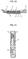
- FIGs. 20 - 22 A conventional technology is described referring to FIGs. 20 - 22 .
- FIG. 20 is a cross sectional view of a conventional loudspeaker
- FIG. 21 is a cross sectional view in part of a portable telephone unit showing a state where the loudspeaker is mounted therein.
- a magnetized magnet 1 is sandwiched by an upper plate 2 and a yoke 3 to form a magnetic circuit 4, and a frame 6 is connected to the yoke 3 of magnetic circuit 4.
- a diaphragm 7 coupled with a voice coil 8 is adhered and fixed on the circumference of frame 6 so that the voice coil 8 is inserted in a magnetic gap 5 of magnetic circuit 4.
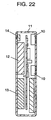
- FIG. 21 and 22 respectively, show a state where a conventional loudspeaker 10 is mounted in a portable telephone unit.
- a display device 12 is disposed in the outer case 11 of portable telephone unit, and a loudspeaker 10 is disposed on a reverse surface of an outer case, or a surface opposite to the display device 12.
- An operation section 13 is disposed besides the display device 12. Furthermore, a receiver 14 is provided next to the display device 12.
- the loudspeaker 10 is also requested to be still more downsized, and to have a greater freedom in the mounting disposition. It is essential to make an area of the diaphragm 7 smaller if a loudspeaker 10 is to be downsized; however, a diaphragm 7 having a reduced area accompanies a problem of reduced sound pressure level.
- a telephone unit needs to be mounted with a plurality of loudspeakers 10.
- the loudspeaker 10 is requested to become more compact.
- US 5,850,460 relates to a two-diaphragm speaker configuration for use as a bass speaker.
- Speaker 1a is acoustically coupled via enclosure 6a to the passive radiator 2a including a diaphragm.
- a box-shaped housing mounts speaker 1a and passive radiator 2a at opposite sides of enclosures 6a.
- a similar device is known from US 4385 210 .
- the present invention aims to provide a loudspeaker that contributes to a further downsizing of the electronic apparatus such as a portable telephone units and the like.
- the second diaphragm is divided into portions and the divided portions are connected with a flexible material, and the thickness of the second diaphragm can be varied depending on a portion.
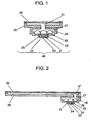
- FIG. 1 shows a cross sectional view of a loudspeaker in accordance with an exemplary embodiment of the present invention.
- a loudspeaker in the first exemplary embodiment comprises a box 29 provided at the opening with a substantially flat second diaphragm 30, and a sound generator 40.
- the sound generator 40 comprises an inner magnet type magnetic circuit 24 with a magnetized magnet 21 sandwiched by an upper plate 22 and a yoke 23.
- a frame 26 is connected to the yoke 23 of magnetic circuit 24, a first diaphragm 27 is bonded to the circumference of the frame 26, and the first diaphragm 27 is coupled with a voice coil 28.
- the voice coil 28 is inserted in a magnetic gap 25 of the magnetic circuit 24.
- a box 29 is connected to the circumference of the frame 26, and the box 29 is provided with a substantially flat second diaphragm 30 bonded to the opening of the box 29.
- the first diaphragm 27 and the second diaphragm 30 are acoustically coupled via an enclosure 31. Area of the second diaphragm 30 in the present embodiment is greater than that of the first diaphragm 27.
- a shape of the enclosure 31 as well as positioning and a shape of the first and the second diaphragms can be designed at a designer's option.
- a designer will have a greater designing freedom in producing a compact portable telephone unit, while evading a degradation in the sound pressure of reproduced sound with a use of a larger-sized diaphragm.
- the sound generator 40 is described based on a dynamic electro-acoustic transducer.
- the sound generator 40 is not limited to the dynamic electro-acoustic transducer; it can be an electrostatic transducer or a piezoelectric transducer.
- the second diaphragm 30 may have a thickness of 0.05 - 10 mm, depending on a total size of the apparatus. Thus a portable telephone unit or the like equipment can be designed to have a thinner profile.
- a gap size underneath the second diaphragm 30 may be 0.01 - 10 mm.
- a portable telephone unit or a larger equipment can be designed to provide a still thinner profile.
- box 29 and the frame 26 have been explained as discrete members.
- a loudspeaker in accordance with a second exemplary embodiment of the present invention is described referring to FIG. 2 .
- the point of difference as compared with that in the first exemplary embodiment is that the frame 26 is disposed at an end portion of the box 29.
- the first diaphragm 27 can be disposed at a portion corresponding to an end part of the second diaphragm 30 by making use of the enclosure 31.
- a portable telephone unit having a large second diaphragm 30 can be provided in a still reduced overall dimension.
- a specific area among the outer surfaces of an electronic apparatus can be utilized as the second diaphragm 30.
- highly efficient designing of an electronic apparatus can be expected.
- a loudspeaker in accordance with a third exemplary embodiment is described in the following.
- the point of difference as compared with the first exemplary embodiment is that the second diaphragm 30 and the box 29 in the present exemplary embodiment are made of a transparent material.
- the second diaphragm 30 as well as the box 29 can be seen through to the their bottom or the back.
- a display device or the like components can be disposed at an efficient space factor.
- they can be disposed not only in the surface area next to a loudspeaker or second diaphragm 30, but they can be also disposed in a space behind the loudspeaker or the second diaphragm 30.
- a still larger designing freedom and a portable telephone unit having a large second diaphragm 30 can be obtained in a more compact contour.
- FIG. 3 is a partial cross sectional view of a portable telephone unit incorporating a loudspeaker provided in accordance with the second exemplary embodiment of the present invention.
- a module 50 comprising a display device 41 and a loudspeaker of the second embodiment is mounted in a portable telephone unit.
- a diaphragm 30 and a box 29 of the loudspeaker in the present embodiment are made of a transparent film and a transparent resin.
- a display device 41 is disposed in a space underneath the diaphragm 30 and the box to form an integrated module.
- the transparent diaphragm 30 and the transparent box 29 enable the present module.
- An integration of a loudspeaker and a display device into module leads to a reduced number of processing steps during production, and to an effective parts supply management. These eventually contribute to a cost reduction.
- FIG. 4 is a partial cross sectional view of a portable telephone unit 51 incorporating a module 50 described the fourth exemplary embodiment.
- key portion of the portable telephone unit 51 comprises the module 50 and an operation section 42, both of them connected and housed in an outer case 52. Disposing the operation section 42 next to the module 50 enables downsizing of a portable telephone unit 51, and increases the designing freedom.
- a loudspeaker in accordance with a sixth exemplary embodiment of the present invention is described referring to FIG. 5 .
- two sound generators 40 are provided at both end portions of the box 29 (second diaphragm 30) of the second exemplary embodiment.
- the disposition of the two first diaphragms 27 in an opposing arrangement at both ends of the diaphragm 30 leads to a further downsizing of a portable telephone unit having a large-size diaphragm 30, and to a larger designing freedom.
- the above configuration allows a designer a freedom to design a shape of the enclosure 31, where a shape and locations of the respective diaphragms can be designed at a designer's option.
- the sound generators 40 are disposed with a long distance between each other, as shown in FIG. 6 , it effectively reduces cross talk between the right and the left channels in receiving stereophonic signals.
- area of the diaphragm 30 in the present preferred embodiment is greater than at least double the area of diaphragm 27 of the sound generator 40.
- the sound pressure of a loudspeaker is increased by the use of a large-sized diaphragm 30 and a plurality of sound generators 40. Since the space between the sound generators can be utilized by other components effectively, the compactness is not sacrificed and a loudspeaker can provide a great sound pressure in accordance with the present preferred embodiment.
- a diaphragm 30 may be provided with four sound generators disposed around, and one among a plurality of sound generators may be used for a buzzer, and many other modifications may be developed.
- the size of individual sound generator can be reduced, which contributes to a further downsizing of an apparatus.
- a module in accordance with a seventh exemplary embodiment of the present invention is described with reference to FIG. 7 .
- a loudspeaker in the sixth exemplary embodiment comprising a transparent second diaphragm 30 and a transparent box 29 is integrated with a display device 41 into a module 60.
- the diaphragm 30 is disposed in the front and covering the display device 41.
- the modular component is advantageous in reducing the number of process steps during assembly of an electronic apparatus and effective components supply management. This leads to a reduced cost.
- the module 60 in the present preferred embodiment can be mounted in an outer case 52, as shown in FIG. 8 , to produce a portable telephone unit 51.
- the portable telephone unit 51 comprises at least a module 60 and an operation section 42.
- the use of a module 60 contributes to reduce the overall size, to thin and to provide more designing freedom with the portable telephone unit 51.
- a loudspeaker module 50 may be disposed in any layouts in accordance with a function and a design, such as in a lengthwise arrangement or in a lateral arrangement in the outer case 52 of portable telephone unit 51.
- both of the display device 41 and the operation section 42 can be disposed in a space underneath the transparent diaphragm 30. This arrangement enables a further downsizing of a portable telephone unit 51 and provides a further increased designing freedom.
- the operation section 42 can be operated by giving a pressing force with a finger, for example, from above the transparent second diaphragm 30.
- a diaphragm 30 can be shared by a receiver, which used to be provided independently.
- a receiver sound-hole which used to be an indispensable item can be eliminated to provide a remarkably improved waterproof or drip-proof property.
- a broad vibration area of the large-sized diaphragm provides a wider service area.
- FIG. 9 An eighth exemplary embodiment of the present invention is described with reference to FIG. 9 .
- a second diaphragm 30 of the third exemplary embodiment is divided into two portions at substantially the middle, and two portions are connected with a flexible material 33. This configuration contributes to an improved channel separation at stereophonic sound reproduction.
- the diaphragm 30 of the embodiment 3 sounds generated from the two sound generators are sometimes mixed together causing a cross talk. This often affects the channel separation at stereophonic sound reproduction to a deteriorated stereophonic atmosphere.
- the second diaphragm 30 in accordance with the present exemplary embodiment which is divided into two portions at substantially the middle, provides an improved channel separation during stereophonic sound reproduction.
- a silicone resin As to the material 33 for dividing a diaphragm 30 into two portions, a silicone resin, a rubber, a thermoplastic elastomer, a foamed resin and the like may be used.
- Silicone resin has a superior waterproof property, and provides a stable channel separation during sound reproduction in stereo channel under a wide temperature range. Rubber materials provide a designer with a broad selection range in the flexibility. Thus, rubber is suitable when a critical adjustment of channel separation is requested.
- Thermoplastic elastomer is advantageous in high productivity and a reduced cost. Foamed resin has a great internal loss, which leads to a remarkable channel separation effect.
- a display device 41 can be disposed underneath the diaphragm 30 without inviting visual hazard.
- the loudspeaker of the present exemplary embodiment and the display device 41 can be integrated into a module 70.
- An integration of a loudspeaker and a display device into module contributes to reduce a number of process steps during the production, and to an effective parts supply management. These lead to a reduced cost.
- a ninth exemplary embodiment of the present invention is described with reference to FIG. 13 .
- FIG. 13 illustrates a loudspeaker of the first exemplary embodiment wherein a thickness of the second diaphragm 30 differs depending on a portion.
- a loudspeaker in the present embodiment has a diaphragm 30, which has a thin groove area A at an outer circumference. Vibration mode of the diaphragm 30 is adjustable by changing its partial thickness. Thus, the sound pressure /frequency characteristic and the distortion characteristic can be controlled to produce favorable characteristics.
- the loudspeaker in the first exemplary embodiment has a difficulty in controlling the vibration mode of diaphragm 30 in some cases, and the frequency characteristics sometimes become unstable.
- the vibration mode can be controlled by changing partial thickness of the diaphragm 30. As a result, a compact loudspeaker yet having superior frequency characteristic and distortion characteristic is produced .
- the channel separation at stereo sound reproduction can be improved by providing a long distance between the first diaphragms 27 disposed right and left as shown in FIG. 14(a) .
- the second diaphragm 30 may be further provided with grooves 34, as shown in FIG. 15 .
- the grooves 34 suppress propagation of vibration to change the vibration mode.
- the frequency characteristic and the distortion characteristic can also be put under a finer control by making use of the grooves 34.
- the resultant effects include, a reduced unnecessary resonance of diaphragm 30, a lower distortion, a high fidelity sound reproduction, and so on, which integrally lead to further improved frequency characteristics.
- grooves 34 are carefully provided to halfway of the material thickness of diaphragm 30 in order not to introduce air leakage.
- the vibration mode of diaphragm 30 can be optimized by gradually increasing its thickness from a center to an outer periphery, as shown in FIG. 16 .
- the thinned material thickness of diaphragm 30 at the central area and the vicinity reduces mass of the diaphragm, which improves the sound pressure level at high frequency range and extends the frequency limit at high frequency range.
- the thickness in the intermediary region is kept normal, and that at the outer periphery is increased to optimize the total weight balance of the diaphragm to reproduce the sound favorably down to a low frequency range.
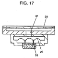
- material thickness of the diaphragm 30 can be thinned gradually from the central area towards the outer periphery as shown in FIG. 17 .
- the greater mass in the central area makes the vibration mode of a diaphragm 30 as that of a high-cut filter.
- a sound of a middle- and high-frequency range are cut off and a heavy low sound can be reproduced.
- a display device 41 and a loudspeaker in the present embodiment can be integrated into a module 80, as shown in FIG. 18(a) in the same way as in the foregoing exemplary embodiments.
- This configuration provides a further downsizing and designing freedom with an electronic apparatus, as well as improved frequency characteristics.
- a diaphragm 30 of FIG. 18(a) a thin groove areas A are provided as shown in FIG. 18(b) , for controlling the frequency characteristics.
- the module 80 is built in a portable telephone unit or other electronic apparatus, as shown in FIG. 19 .
- the module 80 enables to reduce the number of process steps during production and to simplify the parts supply management, while maintaining favorable frequency characteristics of an electronic apparatus. Thus, the module 80 eventually lead to a cost reduction.
- a loudspeaker in the present invention comprises an enclosure having a second diaphragm disposed at an open end, and at least one sound generator coupled acoustically with the enclosure.
- the sound generator has a first diaphragm
- the second diaphragm is characterized in that it has a greater area than that of the first diaphragm.
- the present invention allows a free optimization of respective diaphragms in terms of the positioning and shape, and downsizes a loudspeaker module and a portable electronic apparatus. Furthermore, the present invention provides an improved channel separation at stereo sound reproduction by a compact apparatus.
Landscapes
- Engineering & Computer Science (AREA)
- Signal Processing (AREA)
- Physics & Mathematics (AREA)
- Acoustics & Sound (AREA)
- Health & Medical Sciences (AREA)
- Otolaryngology (AREA)
- Multimedia (AREA)
- Telephone Set Structure (AREA)
- Details Of Audible-Bandwidth Transducers (AREA)
Description
- The present invention relates to a loudspeaker, a loudspeaker module using the loudspeaker and an electronic apparatus such as a portable telephone unit, a communication apparatus, a game unit or the like, using the loudspeaker or the loudspeaker module.
- A conventional technology is described referring to
FIGs. 20 - 22 . -
FIG. 20 is a cross sectional view of a conventional loudspeaker,FIG. 21 is a cross sectional view in part of a portable telephone unit showing a state where the loudspeaker is mounted therein. - Referring to
FIG. 20 , a magnetized magnet 1 is sandwiched by anupper plate 2 and ayoke 3 to form amagnetic circuit 4, and aframe 6 is connected to theyoke 3 ofmagnetic circuit 4. Adiaphragm 7 coupled with avoice coil 8 is adhered and fixed on the circumference offrame 6 so that thevoice coil 8 is inserted in amagnetic gap 5 ofmagnetic circuit 4. -
FIG. 21 and22 , respectively, show a state where aconventional loudspeaker 10 is mounted in a portable telephone unit. Adisplay device 12 is disposed in theouter case 11 of portable telephone unit, and aloudspeaker 10 is disposed on a reverse surface of an outer case, or a surface opposite to thedisplay device 12. Anoperation section 13 is disposed besides thedisplay device 12. Furthermore, areceiver 14 is provided next to thedisplay device 12. - In the recent requirements towards small-sized and multi-functioning of the portable telephone units and other electronic appliances, the
loudspeaker 10 is also requested to be still more downsized, and to have a greater freedom in the mounting disposition. It is essential to make an area of thediaphragm 7 smaller if aloudspeaker 10 is to be downsized; however, adiaphragm 7 having a reduced area accompanies a problem of reduced sound pressure level. - Among the compact-sized portable telephone units, some are further requested to be compatible with stereo-phonic signals; then a telephone unit needs to be mounted with a plurality of
loudspeakers 10. In such a case, theloudspeaker 10 is requested to become more compact. -
US 5,850,460 relates to a two-diaphragm speaker configuration for use as a bass speaker. Speaker 1a is acoustically coupled via enclosure 6a to the passive radiator 2a including a diaphragm. A box-shaped housing mounts speaker 1a and passive radiator 2a at opposite sides of enclosures 6a. A similar device is known fromUS 4385 210 . - The present invention aims to provide a loudspeaker that contributes to a further downsizing of the electronic apparatus such as a portable telephone units and the like.
- This is achieved by the subject matter of the independent claim. Advantageous embodiments are set forth in the dependent claims.
- Depending on needs, the second diaphragm is divided into portions and the divided portions are connected with a flexible material, and the thickness of the second diaphragm can be varied depending on a portion.
-
FIG. 1 is a cross sectional view of a loudspeaker in accordance with an exemplary embodiment of the present invention. -
FIG. 2 is a cross sectional view of a loudspeaker in accordance with other exemplary embodiment of the present invention. -
FIG. 3 is a cross sectional view of a portable telephone unit mounted with the loudspeaker ofFIG. 2 . -
FIG. 4 is a cross sectional view of a portable telephone unit in accordance with an exemplary embodiment of the present invention. -
FIG. 5 is a cross sectional view of a loudspeaker in accordance with another embodiment of the present invention. -
FIG. 6 is a cross sectional view of a loudspeaker in accordance with still another embodiment of the present invention. -
FIG. 7 is a cross sectional view of a module in which the loudspeaker ofFIG. 6 and a display device are integrated. -
FIG. 8 is a cross sectional view of a portable telephone unit incorporating the module ofFIG. 7 . -
FIG. 9 is a cross sectional view of a loudspeaker in accordance with yet another embodiment of the present invention. -
FIG. 10(a) is a cross sectional view of a loudspeaker in accordance with still other embodiment of the present invention. -
FIG. 10(b) is a cross sectional magnified view showing a key portion ofFIG. 2(a) . -
FIG. 11 is a cross sectional view of a loudspeaker in accordance with still other embodiment of the present invention. -
FIG. 12 is a cross sectional view of a module in which the loudspeaker ofFIG. 10 and a display device are integrated. -
FIG. 13 is a cross sectional view of a loudspeaker in accordance with still other embodiment of the present invention. -
FIG. 14(a) is a cross sectional view of a loudspeaker in accordance with still other embodiment of the present invention. -
FIG. 14(b) is a cross sectional magnified view showing a key portion ofFIG. 14(a) . -
FIG. 15(a) is a cross sectional view of a loudspeaker in accordance with still other embodiment of the present invention. -
FIG. 15(b) is a cross sectional magnified view showing key portions ofFIG. 15(a) . -
FIG. 15(c) is a cross sectional magnified view showing key portions ofFIG. 15(a) . -
FIG. 16 is a cross sectional view of a loudspeaker in accordance with still other embodiment of the present invention. -
FIG. 17 is a cross sectional view of a loudspeaker in accordance with still other embodiment of the present invention. -
FIG. 18(a) is a cross sectional view of a module in accordance with an exemplary embodiment of the present invention. -
FIG. 18(b) is a cross sectional magnified view showing key portions ofFIG. 18(a) . -
FIG. 19(a) is a cross sectional view of a portable telephone unit in accordance with an exemplary embodiment of the present invention. -
FIG. 19(b) is a cross sectional magnified view showing key portions ofFIG. 19(a) . -
FIG. 20 is a cross sectional view of a conventional loudspeaker. -
FIG. 21 is a cross sectional view of a conventional portable telephone unit. -
FIG. 22 is a cross sectional view of another conventional portable telephone unit. - Now in the following, exemplary embodiments of the present invention will be described with reference to the drawings.
-
FIG. 1 shows a cross sectional view of a loudspeaker in accordance with an exemplary embodiment of the present invention. - A loudspeaker in the first exemplary embodiment comprises a
box 29 provided at the opening with a substantially flatsecond diaphragm 30, and asound generator 40. - The
sound generator 40 comprises an inner magnet typemagnetic circuit 24 with amagnetized magnet 21 sandwiched by anupper plate 22 and ayoke 23. Aframe 26 is connected to theyoke 23 ofmagnetic circuit 24, afirst diaphragm 27 is bonded to the circumference of theframe 26, and thefirst diaphragm 27 is coupled with avoice coil 28. Thevoice coil 28 is inserted in amagnetic gap 25 of themagnetic circuit 24. - A
box 29 is connected to the circumference of theframe 26, and thebox 29 is provided with a substantially flatsecond diaphragm 30 bonded to the opening of thebox 29. Thefirst diaphragm 27 and thesecond diaphragm 30 are acoustically coupled via anenclosure 31. Area of thesecond diaphragm 30 in the present embodiment is greater than that of thefirst diaphragm 27. - In a structure in accordance with the present invention, a shape of the
enclosure 31 as well as positioning and a shape of the first and the second diaphragms can be designed at a designer's option. Thus a designer will have a greater designing freedom in producing a compact portable telephone unit, while evading a degradation in the sound pressure of reproduced sound with a use of a larger-sized diaphragm. - In the above description, the
sound generator 40 is described based on a dynamic electro-acoustic transducer. However, thesound generator 40 is not limited to the dynamic electro-acoustic transducer; it can be an electrostatic transducer or a piezoelectric transducer. - - The
second diaphragm 30 may have a thickness of 0.05 - 10 mm, depending on a total size of the apparatus. Thus a portable telephone unit or the like equipment can be designed to have a thinner profile. - A gap size underneath the
second diaphragm 30 may be 0.01 - 10 mm. Thus a portable telephone unit or a larger equipment can be designed to provide a still thinner profile. - In the above description the
box 29 and theframe 26 have been explained as discrete members. - A loudspeaker in accordance with a second exemplary embodiment of the present invention is described referring to
FIG. 2 . The point of difference as compared with that in the first exemplary embodiment is that theframe 26 is disposed at an end portion of thebox 29. In the above-described configuration in accordance with the present exemplary embodiment, thefirst diaphragm 27 can be disposed at a portion corresponding to an end part of thesecond diaphragm 30 by making use of theenclosure 31. Thus it provides a still larger designing freedom, and a portable telephone unit having a largesecond diaphragm 30 can be provided in a still reduced overall dimension. - Furthermore, according to the present exemplary embodiment, a specific area among the outer surfaces of an electronic apparatus can be utilized as the
second diaphragm 30. Thus highly efficient designing of an electronic apparatus can be expected. - A loudspeaker in accordance with a third exemplary embodiment is described in the following. The point of difference as compared with the first exemplary embodiment is that the
second diaphragm 30 and thebox 29 in the present exemplary embodiment are made of a transparent material. As a result, according to the present embodiment, thesecond diaphragm 30 as well as thebox 29 can be seen through to the their bottom or the back. When designing, for example, a portable telephone unit in the above-described configuration, a display device or the like components can be disposed at an efficient space factor. In other words, they can be disposed not only in the surface area next to a loudspeaker orsecond diaphragm 30, but they can be also disposed in a space behind the loudspeaker or thesecond diaphragm 30. Thus, a still larger designing freedom and a portable telephone unit having a largesecond diaphragm 30 can be obtained in a more compact contour. -
FIG. 3 is a partial cross sectional view of a portable telephone unit incorporating a loudspeaker provided in accordance with the second exemplary embodiment of the present invention. - Referring to
FIG. 3 , amodule 50 comprising adisplay device 41 and a loudspeaker of the second embodiment is mounted in a portable telephone unit. Adiaphragm 30 and abox 29 of the loudspeaker in the present embodiment are made of a transparent film and a transparent resin. In the present exemplary embodiment, adisplay device 41 is disposed in a space underneath thediaphragm 30 and the box to form an integrated module. Thetransparent diaphragm 30 and thetransparent box 29 enable the present module. Thus, a still larger designing freedom and a portable telephone unit having a largesecond diaphragm 30 can be obtained in a more compact contour. - An integration of a loudspeaker and a display device into module leads to a reduced number of processing steps during production, and to an effective parts supply management. These eventually contribute to a cost reduction.
- A sixth exemplary embodiment is described with reference to
FIG. 4. FIG. 4 is a partial cross sectional view of aportable telephone unit 51 incorporating amodule 50 described the fourth exemplary embodiment. - Referring to
FIG. 4 , key portion of theportable telephone unit 51 comprises themodule 50 and anoperation section 42, both of them connected and housed in anouter case 52. Disposing theoperation section 42 next to themodule 50 enables downsizing of aportable telephone unit 51, and increases the designing freedom. - Furthermore, it is also possible to dispose both the
display device 41 and theoperation section 42 in a space underneath the transparentsecond diaphragm 30. Thus further downsizing and a larger designing freedom of aportable telephone unit 51 can be expected. - Although the above description in the present exemplary embodiment has been made based on a portable telephone unit, the concept can be applied to, besides portable telephone unit, various kinds of electronic apparatus such as every kinds of communication equipment, a game unit, a Liquid Crystal TV receiver, a personal computer, a navigation device, and the like.
- A loudspeaker in accordance with a sixth exemplary embodiment of the present invention is described referring to
FIG. 5 . In the present exemplary embodiment, twosound generators 40 are provided at both end portions of the box 29 (second diaphragm 30) of the second exemplary embodiment. The disposition of the twofirst diaphragms 27 in an opposing arrangement at both ends of thediaphragm 30 leads to a further downsizing of a portable telephone unit having a large-size diaphragm 30, and to a larger designing freedom. - Like in the third exemplary embodiment, the above configuration allows a designer a freedom to design a shape of the
enclosure 31, where a shape and locations of the respective diaphragms can be designed at a designer's option. For example, when thesound generators 40 are disposed with a long distance between each other, as shown inFIG. 6 , it effectively reduces cross talk between the right and the left channels in receiving stereophonic signals. - As is understood from the above description, area of the
diaphragm 30 in the present preferred embodiment is greater than at least double the area ofdiaphragm 27 of thesound generator 40. - Thus the sound pressure of a loudspeaker is increased by the use of a large-
sized diaphragm 30 and a plurality ofsound generators 40. Since the space between the sound generators can be utilized by other components effectively, the compactness is not sacrificed and a loudspeaker can provide a great sound pressure in accordance with the present preferred embodiment. - The above explanation is made about an example using two sound generators, but the number of sound generator is not limited to two. For example, a
diaphragm 30 may be provided with four sound generators disposed around, and one among a plurality of sound generators may be used for a buzzer, and many other modifications may be developed. When a plurality of sound generators are used , the size of individual sound generator can be reduced, which contributes to a further downsizing of an apparatus. - A module in accordance with a seventh exemplary embodiment of the present invention is described with reference to
FIG. 7 . In the present exemplary embodiment, a loudspeaker in the sixth exemplary embodiment comprising a transparentsecond diaphragm 30 and atransparent box 29 is integrated with adisplay device 41 into amodule 60. Thediaphragm 30 is disposed in the front and covering thedisplay device 41. The modular component is advantageous in reducing the number of process steps during assembly of an electronic apparatus and effective components supply management. This leads to a reduced cost. - The
module 60 in the present preferred embodiment can be mounted in anouter case 52, as shown inFIG. 8 , to produce aportable telephone unit 51. Theportable telephone unit 51 comprises at least amodule 60 and anoperation section 42. The use of amodule 60 contributes to reduce the overall size, to thin and to provide more designing freedom with theportable telephone unit 51. - A
loudspeaker module 50 may be disposed in any layouts in accordance with a function and a design, such as in a lengthwise arrangement or in a lateral arrangement in theouter case 52 ofportable telephone unit 51. - Furthermore, both of the
display device 41 and theoperation section 42 can be disposed in a space underneath thetransparent diaphragm 30. This arrangement enables a further downsizing of aportable telephone unit 51 and provides a further increased designing freedom. Theoperation section 42 can be operated by giving a pressing force with a finger, for example, from above the transparentsecond diaphragm 30. - In a structure of the present embodiment, a
diaphragm 30 can be shared by a receiver, which used to be provided independently. In this configuration, a receiver sound-hole which used to be an indispensable item can be eliminated to provide a remarkably improved waterproof or drip-proof property. In addition, a broad vibration area of the large-sized diaphragm provides a wider service area. - Although the above explanation has been made based on a portable telephone unit, the concept can be applied to, besides portable telephone unit, various kinds of electronic apparatus such as a communication equipment, a game unit, an LCD TV receiver, a personal computer, a navigation device and the like.
- An eighth exemplary embodiment of the present invention is described with reference to
FIG. 9 . InFIG. 9 , asecond diaphragm 30 of the third exemplary embodiment is divided into two portions at substantially the middle, and two portions are connected with aflexible material 33. This configuration contributes to an improved channel separation at stereophonic sound reproduction. - Namely, with the
diaphragm 30 of theembodiment 3, sounds generated from the two sound generators are sometimes mixed together causing a cross talk. This often affects the channel separation at stereophonic sound reproduction to a deteriorated stereophonic atmosphere. However, thesecond diaphragm 30 in accordance with the present exemplary embodiment, which is divided into two portions at substantially the middle, provides an improved channel separation during stereophonic sound reproduction. - As to the
material 33 for dividing adiaphragm 30 into two portions, a silicone resin, a rubber, a thermoplastic elastomer, a foamed resin and the like may be used. Silicone resin has a superior waterproof property, and provides a stable channel separation during sound reproduction in stereo channel under a wide temperature range. Rubber materials provide a designer with a broad selection range in the flexibility. Thus, rubber is suitable when a critical adjustment of channel separation is requested. Thermoplastic elastomer is advantageous in high productivity and a reduced cost. Foamed resin has a great internal loss, which leads to a remarkable channel separation effect. - As described above, various kinds of effects can be generated by selecting a material for the
flexible material 33. - When the
sound generators 40 are disposed with a large distance between each other as illustrated inFIG. 10 , cross talk between the right and left channels can be further reduced to a still improved channel separation during stereo sound reproduction. - When the
sound generators 40 are disposed, as shown inFIG. 11 , so that a center of eachsound generator 40 coincides with a center of respective divided portions ofdiaphragm 30 divided at the middle, vibration ofdiaphragm 27 can be sent precisely to the corresponding right-left portions of thediaphragm 30. As a result, the unwanted resonance ofdiaphragm 30 is reduced, and a low distortion and a high-fidelity reproduction of the sound are performed. Although the above description has been made on adiaphragm 30 divided into two portions, a diaphragm may be divided into three or more portions and each of the portions may be provided at a center of anindividual diaphragm 27 of thesound generators 40. Thus the concept can be applied to a diaphragm divided into an increased number of portions. - Furthermore, when a transparent material is used for the
material 33 and thesecond diaphragm 30 is made of a transparent film, adisplay device 41 can be disposed underneath thediaphragm 30 without inviting visual hazard. Thus, the loudspeaker of the present exemplary embodiment and thedisplay device 41 can be integrated into amodule 70. - An integration of a loudspeaker and a display device into module contributes to reduce a number of process steps during the production, and to an effective parts supply management. These lead to a reduced cost.
- A ninth exemplary embodiment of the present invention is described with reference to
FIG. 13 . -
FIG. 13 illustrates a loudspeaker of the first exemplary embodiment wherein a thickness of thesecond diaphragm 30 differs depending on a portion. A loudspeaker in the present embodiment has adiaphragm 30, which has a thin groove area A at an outer circumference. Vibration mode of thediaphragm 30 is adjustable by changing its partial thickness. Thus, the sound pressure /frequency characteristic and the distortion characteristic can be controlled to produce favorable characteristics. - Namely, the loudspeaker in the first exemplary embodiment has a difficulty in controlling the vibration mode of
diaphragm 30 in some cases, and the frequency characteristics sometimes become unstable. With the structure of the present exemplary embodiment, however, the vibration mode can be controlled by changing partial thickness of thediaphragm 30. As a result, a compact loudspeaker yet having superior frequency characteristic and distortion characteristic is produced . - Also in the present exemplary embodiment, the channel separation at stereo sound reproduction can be improved by providing a long distance between the
first diaphragms 27 disposed right and left as shown inFIG. 14(a) . - The
second diaphragm 30 may be further provided withgrooves 34, as shown inFIG. 15 . Thegrooves 34 suppress propagation of vibration to change the vibration mode. The frequency characteristic and the distortion characteristic can also be put under a finer control by making use of thegrooves 34. The resultant effects include, a reduced unnecessary resonance ofdiaphragm 30, a lower distortion, a high fidelity sound reproduction, and so on, which integrally lead to further improved frequency characteristics. - It is preferred that the
grooves 34 are carefully provided to halfway of the material thickness ofdiaphragm 30 in order not to introduce air leakage. - Furthermore, the vibration mode of
diaphragm 30 can be optimized by gradually increasing its thickness from a center to an outer periphery, as shown inFIG. 16 . Namely, the thinned material thickness ofdiaphragm 30 at the central area and the vicinity reduces mass of the diaphragm, which improves the sound pressure level at high frequency range and extends the frequency limit at high frequency range. The thickness in the intermediary region is kept normal, and that at the outer periphery is increased to optimize the total weight balance of the diaphragm to reproduce the sound favorably down to a low frequency range. - Contrary to the above-described configuration, material thickness of the
diaphragm 30 can be thinned gradually from the central area towards the outer periphery as shown inFIG. 17 . The greater mass in the central area makes the vibration mode of adiaphragm 30 as that of a high-cut filter. Thus a sound of a middle- and high-frequency range are cut off and a heavy low sound can be reproduced. - Further, a
display device 41 and a loudspeaker in the present embodiment can be integrated into amodule 80, as shown inFIG. 18(a) in the same way as in the foregoing exemplary embodiments. This configuration provides a further downsizing and designing freedom with an electronic apparatus, as well as improved frequency characteristics. In adiaphragm 30 ofFIG. 18(a) a thin groove areas A are provided as shown inFIG. 18(b) , for controlling the frequency characteristics. - The
module 80 is built in a portable telephone unit or other electronic apparatus, as shown inFIG. 19 . Themodule 80 enables to reduce the number of process steps during production and to simplify the parts supply management, while maintaining favorable frequency characteristics of an electronic apparatus. Thus, themodule 80 eventually lead to a cost reduction. - A loudspeaker in the present invention comprises an enclosure having a second diaphragm disposed at an open end, and at least one sound generator coupled acoustically with the enclosure. The sound generator has a first diaphragm, and the second diaphragm is characterized in that it has a greater area than that of the first diaphragm. The present invention allows a free optimization of respective diaphragms in terms of the positioning and shape, and downsizes a loudspeaker module and a portable electronic apparatus. Furthermore, the present invention provides an improved channel separation at stereo sound reproduction by a compact apparatus.
Claims (16)
- A loudspeaker comprising:a box (29) having an opening provided with a second diaphragm (30) disposed at said opening;a frame (26) having a first diaphragm (27) disposed at a circumference of the frame (26); andat least one sound generator (40) connected to the frame (26),wherein, said second diaphragm has an area greater than an area of said first diaphragm,whereinthe frame (26) and the box (29) are discrete members,the frame (26) and the box (29) connected to the frame (26) form an enclosure (31), andthe first diaphragm (27) and the second diaphragm (30) are acoustically coupled by the enclosure (31),wherein the area of said second diaphragm (30) is not less than twice than the area of said first diaphragm (30),wherein said first diaphragm (27) is disposed at a portion corresponding to an end portion of said second diaphragm (30),wherein both of said second diaphragm (30) and said enclosure (31) are made of a transparent material.
- The loudspeaker of claim 1, wherein said sound generator (40) is one selected from the group consisting of a dynamic electro-acoustic transducer, an electrostatic electro-acoustic transducer and a piezoelectric electro-acoustic transducer.
- The loudspeaker of any of claims 1 to 2, wherein a material thickness of said second diaphragm (30) is 0.05 - 10 mm.
- The loudspeaker of any of claims 1 to 3, wherein a gap size of said enclosure beneath said second diaphragm (30) is 0.01 - 10 mm.
- The loudspeaker of any of claims 1 to 4, wherein said transparent material is a resin.
- The loudspeaker of any of claims 1 to 5, wherein said second diaphragm (30) is divided into portions, said portions being connected via a flexible material.
- The loudspeaker of any of claims 1 to 6, wherein said first diaphragm (27) is disposed at substantially a center of respective divided portions of said second diaphragm (30).
- The loudspeaker of claim 7, wherein said flexible material is transparent.
- The loudspeaker of claim 7, wherein said flexible material is one selected from the group consisting of a silicone resin, a rubber, a thermoplastic elastomer and a foamed resin.
- The loudspeaker of any of claims 1 to 9, wherein a material thickness of said second diaphragm (30) differs depending on a portion.
- The loudspeaker of claim 10, wherein a material thickness of said second diaphragm (30) becomes gradually thick from a central area towards a peripheral area.
- The loudspeaker of claim 10, wherein a material thickness of said second diaphragm (30) becomes gradually thin from a central area towards a peripheral area.
- The loudspeaker of any of claims 10 to 12, wherein said second diaphragm (30) is provided with a groove.
- An integrated module comprising:a speaker of any one of claims 1-13; anda display device (41) disposed at a surface of said enclosure, said surface opposing to said second diaphragm (30).
- The integrated module of claim 14, wherein the box is transparent and wherein the display device (41) is disposed underneath said second diaphragm (30) and the transparent box to form the integrated module
- An electronic apparatus comprising:an integrated module according to any of claims 14-15, andan operation section (42).
Applications Claiming Priority (9)
| Application Number | Priority Date | Filing Date | Title |
|---|---|---|---|
| JP2001293804 | 2001-09-26 | ||
| JP2001293804A JP2003102083A (en) | 2001-09-26 | 2001-09-26 | Loudspeaker, module using the same, and electronic device using the same |
| JP2001354499 | 2001-11-20 | ||
| JP2001354499A JP2003158787A (en) | 2001-11-20 | 2001-11-20 | Speaker, speaker module using the same, and electronic device using the same |
| JP2002043022 | 2002-02-20 | ||
| JP2002043022A JP2003244787A (en) | 2002-02-20 | 2002-02-20 | Loudspeaker, module using the same, and electronic device using the same |
| JP2002191900 | 2002-07-01 | ||
| JP2002191900A JP3896913B2 (en) | 2002-07-01 | 2002-07-01 | Speaker, module using the same, and electronic device using the same |
| PCT/JP2002/009926 WO2003028404A1 (en) | 2001-09-26 | 2002-09-26 | Speaker, speaker module, and electronic equipment using the speaker module |
Publications (3)
| Publication Number | Publication Date |
|---|---|
| EP1343349A1 EP1343349A1 (en) | 2003-09-10 |
| EP1343349A4 EP1343349A4 (en) | 2009-04-01 |
| EP1343349B1 true EP1343349B1 (en) | 2013-04-10 |
Family
ID=27482583
Family Applications (1)
| Application Number | Title | Priority Date | Filing Date |
|---|---|---|---|
| EP02772922.7A Expired - Lifetime EP1343349B1 (en) | 2001-09-26 | 2002-09-26 | Speaker, speaker module, and electronic equipment using the speaker module |
Country Status (6)
| Country | Link |
|---|---|
| US (1) | US7020302B2 (en) |
| EP (1) | EP1343349B1 (en) |
| KR (1) | KR100586367B1 (en) |
| CN (1) | CN100596240C (en) |
| TW (1) | TW580841B (en) |
| WO (1) | WO2003028404A1 (en) |
Families Citing this family (40)
| Publication number | Priority date | Publication date | Assignee | Title |
|---|---|---|---|---|
| FI113934B (en) * | 2002-10-24 | 2004-06-30 | Nokia Corp | Waterproof acoustic design suitable for speaker function |
| WO2004098231A1 (en) * | 2003-04-25 | 2004-11-11 | Sanyo Electric Co., Ltd. | Flat type speaker unit, and electric appliance having this unit |
| US7292702B2 (en) * | 2003-04-29 | 2007-11-06 | Dimensional Communications, Inc. | In-wall speaker system method and apparatus |
| US7069061B2 (en) | 2003-07-18 | 2006-06-27 | Sony Ericsson Mobile Communications Ab | Speaker assemblies and mobile terminals including the same |
| JP4196096B2 (en) * | 2003-10-03 | 2008-12-17 | パナソニック株式会社 | Speaker module, electronic apparatus using the same, and apparatus using the speaker module |
| JP4196097B2 (en) * | 2003-10-06 | 2008-12-17 | パナソニック株式会社 | Speaker, speaker module and electronic device using the same |
| EP1551203A4 (en) * | 2003-10-16 | 2009-11-04 | Panasonic Corp | SPEAKER, SPEAKER MODULE, AND ELECTRONIC APPARATUS USING THE SPEAKER MODULE |
| US7634102B2 (en) * | 2003-12-22 | 2009-12-15 | Panasonic Corporation | Speaker and device using the same |
| JP2005318227A (en) * | 2004-04-28 | 2005-11-10 | Matsushita Electric Ind Co Ltd | Electroacoustic transducer and electronic device using the same |
| WO2005115047A1 (en) * | 2004-05-20 | 2005-12-01 | Matsushita Electric Industrial Co., Ltd. | Portable electronic device |
| JP4196114B2 (en) * | 2004-07-01 | 2008-12-17 | パナソニック株式会社 | Electroacoustic transducer and electronic device using the same |
| JP2006166151A (en) * | 2004-12-09 | 2006-06-22 | Citizen Electronics Co Ltd | Loudspeaker for stereo set |
| US8131001B2 (en) * | 2007-08-07 | 2012-03-06 | Onkyo Corporation | Speaker diaphragm and electrodynamic loudspeaker using the same |
| WO2009151892A1 (en) * | 2008-05-19 | 2009-12-17 | Emo Labs, Inc. | Diaphragm with integrated acoustical and optical properties |
| US8189851B2 (en) | 2009-03-06 | 2012-05-29 | Emo Labs, Inc. | Optically clear diaphragm for an acoustic transducer and method for making same |
| CN101902675B (en) * | 2009-05-25 | 2013-04-17 | 巍世科技有限公司 | Thin speaker with enhanced bass sound |
| US20110044476A1 (en) * | 2009-08-14 | 2011-02-24 | Emo Labs, Inc. | System to generate electrical signals for a loudspeaker |
| JP2011101298A (en) * | 2009-11-09 | 2011-05-19 | Sony Corp | Electronic apparatus |
| WO2011118218A1 (en) * | 2010-03-26 | 2011-09-29 | パナソニック株式会社 | Speaker device, audio control device, wall attached with speaker device |
| US9197961B2 (en) * | 2012-09-14 | 2015-11-24 | Htc Corporation | Portable electronic device with internal speaker |
| WO2014143723A2 (en) | 2013-03-15 | 2014-09-18 | Emo Labs, Inc. | Acoustic transducers |
| USD741835S1 (en) | 2013-12-27 | 2015-10-27 | Emo Labs, Inc. | Speaker |
| USD733678S1 (en) | 2013-12-27 | 2015-07-07 | Emo Labs, Inc. | Audio speaker |
| US9264795B2 (en) * | 2014-01-22 | 2016-02-16 | Clean Energy Labs, Llc | Electrically conductive membrane pump/transducer and methods to make and use same |
| USD748072S1 (en) | 2014-03-14 | 2016-01-26 | Emo Labs, Inc. | Sound bar audio speaker |
| TWM499720U (en) * | 2014-10-31 | 2015-04-21 | Jetvox Acoustic Corp | Piezoelectric ceramic dual-band earphone structure |
| KR101690263B1 (en) * | 2015-08-24 | 2016-12-29 | 주식회사 알머스 | Speaker using dynamic speaker and two piezoelectric elements |
| KR101704517B1 (en) | 2016-03-28 | 2017-02-09 | 엘지디스플레이 주식회사 | Display device for generating sound by panel vibration type |
| KR102663406B1 (en) | 2016-04-04 | 2024-05-14 | 엘지디스플레이 주식회사 | Sound generation actuator of panel vibration type and double faced display device with the same |
| KR20170114471A (en) | 2016-04-05 | 2017-10-16 | 엘지디스플레이 주식회사 | Organic light emitting display device |
| US10142738B2 (en) | 2016-03-28 | 2018-11-27 | Lg Display Co., Ltd. | Panel vibration type sound-generating display device |
| US9913045B2 (en) * | 2016-04-18 | 2018-03-06 | Apple Inc. | Piezoelectric speakers for electronic devices |
| US11697134B2 (en) * | 2016-10-31 | 2023-07-11 | Thales Australia Limited | Acoustic transducer |
| EP3410677A1 (en) * | 2017-05-29 | 2018-12-05 | Kyocera Corporation | Communication device |
| KR101919454B1 (en) * | 2017-07-31 | 2018-11-16 | 엘지디스플레이 주식회사 | Display apparatus and computing apparatus |
| KR102593965B1 (en) * | 2017-09-11 | 2023-10-25 | 엘지디스플레이 주식회사 | Display apparatus |
| US10587949B1 (en) | 2018-03-28 | 2020-03-10 | Paul N. Hagman | Acoustically tuned face panel for speaker system |
| KR102668665B1 (en) * | 2019-01-30 | 2024-05-23 | 삼성디스플레이 주식회사 | Display device |
| CN111954124B (en) * | 2020-08-19 | 2025-07-25 | 苏州礼乐乐器股份有限公司 | Full-band high-tone-quality planar resonant loudspeaker with sound beam and sound tunnel |
| CN111954135B (en) * | 2020-08-19 | 2025-02-14 | 苏州礼乐乐器股份有限公司 | A full-band high-quality electronic product speaker with sound beam and sound tunnel |
Family Cites Families (30)
| Publication number | Priority date | Publication date | Assignee | Title |
|---|---|---|---|---|
| JPS5853826Y2 (en) * | 1979-03-20 | 1983-12-07 | 株式会社ケンウッド | flat speaker |
| JPS55135591A (en) | 1979-04-09 | 1980-10-22 | Mitsubishi Rayon Co Ltd | Preparation of fixed microorganism |
| JPS56160086U (en) * | 1980-04-25 | 1981-11-28 | ||
| JPS56160086A (en) | 1980-05-14 | 1981-12-09 | Hitachi Denshi Ltd | Piezoelectric bimorph type transducer |
| JPS572790U (en) * | 1980-06-04 | 1982-01-08 | ||
| JPS572790A (en) | 1980-06-06 | 1982-01-08 | Tokyo Electric Co Ltd | Alarming system for ink ribbon change timing in printer |
| JPS5741392U (en) * | 1980-08-21 | 1982-03-05 | ||
| JPS5741392A (en) | 1980-08-26 | 1982-03-08 | Toyo Soda Mfg Co Ltd | Cathode for electrolysis |
| US4618025A (en) * | 1980-09-15 | 1986-10-21 | Sherman Dan R | Acoustical ducting for speakers and enclosures |
| US4385210A (en) * | 1980-09-19 | 1983-05-24 | Electro-Magnetic Corporation | Electro-acoustic planar transducer |
| JPS58127779A (en) | 1982-01-25 | 1983-07-29 | Ishikawajima Harima Heavy Ind Co Ltd | Drying and heating of dry quenching equipment for coke |
| JPS58127779U (en) * | 1982-02-23 | 1983-08-30 | 富士通テン株式会社 | Automotive super bass reproduction speaker system |
| JPS62186584A (en) | 1986-02-12 | 1987-08-14 | Matsushita Electric Ind Co Ltd | Manufacture of semiconductor element |
| JPS62186584U (en) * | 1986-05-15 | 1987-11-27 | ||
| JPH01159487A (en) | 1987-12-14 | 1989-06-22 | Matsushita Refrig Co Ltd | Rotary type compressor |
| JPH0721021Y2 (en) * | 1988-04-25 | 1995-05-15 | フオスター電機株式会社 | Speaker system |
| JPH0334391A (en) | 1989-06-29 | 1991-02-14 | Toshiba Corp | Solder coating of printed wiring board |
| JPH0334391U (en) * | 1989-08-08 | 1991-04-04 | ||
| DE3929266C1 (en) * | 1989-09-02 | 1991-01-03 | Mercedes-Benz Aktiengesellschaft, 7000 Stuttgart, De | |
| US4997058A (en) * | 1989-10-02 | 1991-03-05 | Bertagni Jose J | Sound transducer |
| US5394478A (en) * | 1992-11-18 | 1995-02-28 | Advanced Composite Audio, Inc. | Low frequency sound generation system for use in vehicular passenger compartments |
| JPH06177809A (en) * | 1992-12-11 | 1994-06-24 | Hitachi Ltd | Portable information communication equipment |
| GB2273847A (en) * | 1992-12-22 | 1994-06-29 | Canon Res Ct Europe Ltd | Loudspeaker having acoustic mirror. |
| JP3144230B2 (en) * | 1994-09-01 | 2001-03-12 | 松下電器産業株式会社 | Bass reproduction speaker |
| MX9801518A (en) * | 1995-09-02 | 1998-05-31 | New Transducers Ltd | VEHICLE FOR PASSENGERS INCLUDING SPEAKERS THAT INCLUDE RADIANT ACOUSTIC ELEMENTS IN THE FORM OF A PANEL. |
| US6694038B1 (en) * | 1996-09-03 | 2004-02-17 | New Transducers Limited | Acoustic device |
| WO1999004597A2 (en) * | 1997-07-18 | 1999-01-28 | Mackie Designs Inc. | Pistonic motion, large excursion passive radiator |
| US7103193B2 (en) * | 2000-09-15 | 2006-09-05 | American Technology Corporation | Bandpass woofer enclosure with multiple acoustic fibers |
| FI20011303A7 (en) * | 2001-06-19 | 2002-12-20 | Nokia Corp | Speaker |
| EP1271998B1 (en) * | 2001-06-28 | 2008-04-16 | Matsushita Electric Industrial Co., Ltd. | Speaker system, mobile terminal device, and electronic device |
-
2002
- 2002-09-25 TW TW091121977A patent/TW580841B/en not_active IP Right Cessation
- 2002-09-26 CN CN02803017A patent/CN100596240C/en not_active Expired - Fee Related
- 2002-09-26 EP EP02772922.7A patent/EP1343349B1/en not_active Expired - Lifetime
- 2002-09-26 KR KR1020037005717A patent/KR100586367B1/en not_active Expired - Fee Related
- 2002-09-26 WO PCT/JP2002/009926 patent/WO2003028404A1/en not_active Ceased
- 2002-09-26 US US10/381,669 patent/US7020302B2/en not_active Expired - Fee Related
Also Published As
| Publication number | Publication date |
|---|---|
| CN1476734A (en) | 2004-02-18 |
| US7020302B2 (en) | 2006-03-28 |
| CN100596240C (en) | 2010-03-24 |
| EP1343349A1 (en) | 2003-09-10 |
| EP1343349A4 (en) | 2009-04-01 |
| US20040037441A1 (en) | 2004-02-26 |
| WO2003028404A1 (en) | 2003-04-03 |
| KR20030048076A (en) | 2003-06-18 |
| KR100586367B1 (en) | 2006-06-08 |
| TW580841B (en) | 2004-03-21 |
Similar Documents
| Publication | Publication Date | Title |
|---|---|---|
| US7020302B2 (en) | Speaker, speaker module, and electronic equipment using the speaker module | |
| US8189841B2 (en) | Acoustic passive radiating | |
| EP1654906B1 (en) | Passive acoustic radiating | |
| US8818006B2 (en) | Speaker system, electronic apparatus using same, and mobile body device | |
| US20080317255A1 (en) | Audio Transducer Component | |
| CN212278462U (en) | Audio Modules and Terminals | |
| US20100027815A1 (en) | Acoustic-Mechanical Vibrating | |
| EP1401237B1 (en) | Asymmetrical loudspeaker enclosures with enhanced low frequency response | |
| US9769559B2 (en) | Sound transducer acoustic back cavity system | |
| EP2356822B1 (en) | Electronic devices including substrate mounted acoustic actuators and related methods and mobile radiotelephones | |
| CN1489362A (en) | Structural arrangement for a wireless communication terminal including loudspeaker and earphone | |
| CA2094616C (en) | Compact loudspeaker assembly | |
| US8301188B2 (en) | Electronic devices including substrate mounted acoustic actuators and related methods and mobile radiotelephones | |
| CN114071337A (en) | Audio module, terminal and control method | |
| JP4379215B2 (en) | Electroacoustic transducer and module, electronic apparatus and apparatus using the same | |
| JP3896913B2 (en) | Speaker, module using the same, and electronic device using the same | |
| GB2408404A (en) | Fabrication of enclosures for sonic devices, e.g. speakers | |
| JP2003244787A (en) | Loudspeaker, module using the same, and electronic device using the same | |
| CN219019017U (en) | Speaker and electronic equipment | |
| CN121692028A (en) | A loudspeaker and electronic device | |
| CN121792645A (en) | Electronic equipment | |
| JP2005184587A (en) | Speaker, module using the same, and electronic device | |
| HK1149409B (en) | Acoustic passive radiating | |
| HK1093656B (en) | Passive acoustic radiating |
Legal Events
| Date | Code | Title | Description |
|---|---|---|---|
| PUAI | Public reference made under article 153(3) epc to a published international application that has entered the european phase |
Free format text: ORIGINAL CODE: 0009012 |
|
| 17P | Request for examination filed |
Effective date: 20030424 |
|
| AK | Designated contracting states |
Kind code of ref document: A1 Designated state(s): AT BE BG CH CY CZ DE DK EE ES FI FR GB GR IE IT LI LU MC NL PT SE TR |
|
| RAP1 | Party data changed (applicant data changed or rights of an application transferred) |
Owner name: PANASONIC CORPORATION |
|
| A4 | Supplementary search report drawn up and despatched |
Effective date: 20090226 |
|
| 17Q | First examination report despatched |
Effective date: 20100202 |
|
| GRAP | Despatch of communication of intention to grant a patent |
Free format text: ORIGINAL CODE: EPIDOSNIGR1 |
|
| RBV | Designated contracting states (corrected) |
Designated state(s): AT BE BG CH CY CZ DE DK EE ES FI FR GB GR IE IT LI LU MC NL PT SE SK TR |
|
| GRAS | Grant fee paid |
Free format text: ORIGINAL CODE: EPIDOSNIGR3 |
|
| GRAA | (expected) grant |
Free format text: ORIGINAL CODE: 0009210 |
|
| AK | Designated contracting states |
Kind code of ref document: B1 Designated state(s): AT BE BG CH CY CZ DE DK EE ES FI FR GB GR IE IT LI LU MC NL PT SE SK TR |
|
| REG | Reference to a national code |
Ref country code: GB Ref legal event code: FG4D |
|
| REG | Reference to a national code |
Ref country code: CH Ref legal event code: EP Ref country code: AT Ref legal event code: REF Ref document number: 606579 Country of ref document: AT Kind code of ref document: T Effective date: 20130415 |
|
| REG | Reference to a national code |
Ref country code: IE Ref legal event code: FG4D |
|
| REG | Reference to a national code |
Ref country code: DE Ref legal event code: R096 Ref document number: 60244802 Country of ref document: DE Effective date: 20130606 |
|
| REG | Reference to a national code |
Ref country code: AT Ref legal event code: MK05 Ref document number: 606579 Country of ref document: AT Kind code of ref document: T Effective date: 20130410 |
|
| REG | Reference to a national code |
Ref country code: NL Ref legal event code: VDEP Effective date: 20130410 |
|
| PG25 | Lapsed in a contracting state [announced via postgrant information from national office to epo] |
Ref country code: PT Free format text: LAPSE BECAUSE OF FAILURE TO SUBMIT A TRANSLATION OF THE DESCRIPTION OR TO PAY THE FEE WITHIN THE PRESCRIBED TIME-LIMIT Effective date: 20130812 Ref country code: SE Free format text: LAPSE BECAUSE OF FAILURE TO SUBMIT A TRANSLATION OF THE DESCRIPTION OR TO PAY THE FEE WITHIN THE PRESCRIBED TIME-LIMIT Effective date: 20130410 Ref country code: NL Free format text: LAPSE BECAUSE OF FAILURE TO SUBMIT A TRANSLATION OF THE DESCRIPTION OR TO PAY THE FEE WITHIN THE PRESCRIBED TIME-LIMIT Effective date: 20130410 Ref country code: AT Free format text: LAPSE BECAUSE OF FAILURE TO SUBMIT A TRANSLATION OF THE DESCRIPTION OR TO PAY THE FEE WITHIN THE PRESCRIBED TIME-LIMIT Effective date: 20130410 Ref country code: BE Free format text: LAPSE BECAUSE OF FAILURE TO SUBMIT A TRANSLATION OF THE DESCRIPTION OR TO PAY THE FEE WITHIN THE PRESCRIBED TIME-LIMIT Effective date: 20130410 Ref country code: GR Free format text: LAPSE BECAUSE OF FAILURE TO SUBMIT A TRANSLATION OF THE DESCRIPTION OR TO PAY THE FEE WITHIN THE PRESCRIBED TIME-LIMIT Effective date: 20130711 Ref country code: ES Free format text: LAPSE BECAUSE OF FAILURE TO SUBMIT A TRANSLATION OF THE DESCRIPTION OR TO PAY THE FEE WITHIN THE PRESCRIBED TIME-LIMIT Effective date: 20130721 |
|
| PGFP | Annual fee paid to national office [announced via postgrant information from national office to epo] |
Ref country code: DE Payment date: 20130927 Year of fee payment: 12 Ref country code: FI Payment date: 20130923 Year of fee payment: 12 |
|
| PG25 | Lapsed in a contracting state [announced via postgrant information from national office to epo] |
Ref country code: CY Free format text: LAPSE BECAUSE OF FAILURE TO SUBMIT A TRANSLATION OF THE DESCRIPTION OR TO PAY THE FEE WITHIN THE PRESCRIBED TIME-LIMIT Effective date: 20130410 Ref country code: BG Free format text: LAPSE BECAUSE OF FAILURE TO SUBMIT A TRANSLATION OF THE DESCRIPTION OR TO PAY THE FEE WITHIN THE PRESCRIBED TIME-LIMIT Effective date: 20130710 |
|
| PGFP | Annual fee paid to national office [announced via postgrant information from national office to epo] |
Ref country code: GB Payment date: 20130925 Year of fee payment: 12 |
|
| PG25 | Lapsed in a contracting state [announced via postgrant information from national office to epo] |
Ref country code: SK Free format text: LAPSE BECAUSE OF FAILURE TO SUBMIT A TRANSLATION OF THE DESCRIPTION OR TO PAY THE FEE WITHIN THE PRESCRIBED TIME-LIMIT Effective date: 20130410 Ref country code: DK Free format text: LAPSE BECAUSE OF FAILURE TO SUBMIT A TRANSLATION OF THE DESCRIPTION OR TO PAY THE FEE WITHIN THE PRESCRIBED TIME-LIMIT Effective date: 20130410 Ref country code: EE Free format text: LAPSE BECAUSE OF FAILURE TO SUBMIT A TRANSLATION OF THE DESCRIPTION OR TO PAY THE FEE WITHIN THE PRESCRIBED TIME-LIMIT Effective date: 20130410 Ref country code: CZ Free format text: LAPSE BECAUSE OF FAILURE TO SUBMIT A TRANSLATION OF THE DESCRIPTION OR TO PAY THE FEE WITHIN THE PRESCRIBED TIME-LIMIT Effective date: 20130410 |
|
| PGFP | Annual fee paid to national office [announced via postgrant information from national office to epo] |
Ref country code: FR Payment date: 20130920 Year of fee payment: 12 |
|
| PLBE | No opposition filed within time limit |
Free format text: ORIGINAL CODE: 0009261 |
|
| STAA | Information on the status of an ep patent application or granted ep patent |
Free format text: STATUS: NO OPPOSITION FILED WITHIN TIME LIMIT |
|
| PG25 | Lapsed in a contracting state [announced via postgrant information from national office to epo] |
Ref country code: IT Free format text: LAPSE BECAUSE OF FAILURE TO SUBMIT A TRANSLATION OF THE DESCRIPTION OR TO PAY THE FEE WITHIN THE PRESCRIBED TIME-LIMIT Effective date: 20130410 |
|
| 26N | No opposition filed |
Effective date: 20140113 |
|
| REG | Reference to a national code |
Ref country code: DE Ref legal event code: R097 Ref document number: 60244802 Country of ref document: DE Effective date: 20140113 |
|
| PG25 | Lapsed in a contracting state [announced via postgrant information from national office to epo] |
Ref country code: MC Free format text: LAPSE BECAUSE OF FAILURE TO SUBMIT A TRANSLATION OF THE DESCRIPTION OR TO PAY THE FEE WITHIN THE PRESCRIBED TIME-LIMIT Effective date: 20130410 |
|
| REG | Reference to a national code |
Ref country code: CH Ref legal event code: PL |
|
| REG | Reference to a national code |
Ref country code: IE Ref legal event code: MM4A |
|
| PG25 | Lapsed in a contracting state [announced via postgrant information from national office to epo] |
Ref country code: LI Free format text: LAPSE BECAUSE OF NON-PAYMENT OF DUE FEES Effective date: 20130930 Ref country code: IE Free format text: LAPSE BECAUSE OF NON-PAYMENT OF DUE FEES Effective date: 20130926 Ref country code: CH Free format text: LAPSE BECAUSE OF NON-PAYMENT OF DUE FEES Effective date: 20130930 |
|
| REG | Reference to a national code |
Ref country code: DE Ref legal event code: R119 Ref document number: 60244802 Country of ref document: DE |
|
| PG25 | Lapsed in a contracting state [announced via postgrant information from national office to epo] |
Ref country code: FI Free format text: LAPSE BECAUSE OF NON-PAYMENT OF DUE FEES Effective date: 20140926 |
|
| GBPC | Gb: european patent ceased through non-payment of renewal fee |
Effective date: 20140926 |
|
| REG | Reference to a national code |
Ref country code: DE Ref legal event code: R119 Ref document number: 60244802 Country of ref document: DE Effective date: 20150401 |
|
| REG | Reference to a national code |
Ref country code: FR Ref legal event code: ST Effective date: 20150529 |
|
| PG25 | Lapsed in a contracting state [announced via postgrant information from national office to epo] |
Ref country code: TR Free format text: LAPSE BECAUSE OF FAILURE TO SUBMIT A TRANSLATION OF THE DESCRIPTION OR TO PAY THE FEE WITHIN THE PRESCRIBED TIME-LIMIT Effective date: 20130410 |
|
| PG25 | Lapsed in a contracting state [announced via postgrant information from national office to epo] |
Ref country code: DE Free format text: LAPSE BECAUSE OF NON-PAYMENT OF DUE FEES Effective date: 20150401 Ref country code: GB Free format text: LAPSE BECAUSE OF NON-PAYMENT OF DUE FEES Effective date: 20140926 Ref country code: LU Free format text: LAPSE BECAUSE OF NON-PAYMENT OF DUE FEES Effective date: 20130926 |
|
| PG25 | Lapsed in a contracting state [announced via postgrant information from national office to epo] |
Ref country code: FR Free format text: LAPSE BECAUSE OF NON-PAYMENT OF DUE FEES Effective date: 20140930 |