EP1343031A1 - Convertisseur de mode optique - Google Patents
Convertisseur de mode optique Download PDFInfo
- Publication number
- EP1343031A1 EP1343031A1 EP03290509A EP03290509A EP1343031A1 EP 1343031 A1 EP1343031 A1 EP 1343031A1 EP 03290509 A EP03290509 A EP 03290509A EP 03290509 A EP03290509 A EP 03290509A EP 1343031 A1 EP1343031 A1 EP 1343031A1
- Authority
- EP
- European Patent Office
- Prior art keywords
- mode
- converter according
- optical
- guide
- mode converter
- Prior art date
- Legal status (The legal status is an assumption and is not a legal conclusion. Google has not performed a legal analysis and makes no representation as to the accuracy of the status listed.)
- Withdrawn
Links
- 230000003287 optical effect Effects 0.000 title claims abstract description 61
- 238000009826 distribution Methods 0.000 claims abstract description 14
- 230000007704 transition Effects 0.000 claims abstract description 7
- 238000006243 chemical reaction Methods 0.000 claims description 19
- 239000013307 optical fiber Substances 0.000 claims description 4
- 229910052732 germanium Inorganic materials 0.000 claims description 3
- GNPVGFCGXDBREM-UHFFFAOYSA-N germanium atom Chemical compound [Ge] GNPVGFCGXDBREM-UHFFFAOYSA-N 0.000 claims description 3
- 230000003595 spectral effect Effects 0.000 claims description 3
- 238000011084 recovery Methods 0.000 claims description 2
- 239000000835 fiber Substances 0.000 description 22
- 238000000034 method Methods 0.000 description 14
- 101710121003 Oxygen-evolving enhancer protein 3, chloroplastic Proteins 0.000 description 8
- 230000006978 adaptation Effects 0.000 description 8
- 230000005684 electric field Effects 0.000 description 8
- 230000004048 modification Effects 0.000 description 7
- 238000012986 modification Methods 0.000 description 7
- 206010034972 Photosensitivity reaction Diseases 0.000 description 5
- 230000036211 photosensitivity Effects 0.000 description 5
- 230000008878 coupling Effects 0.000 description 4
- 238000010168 coupling process Methods 0.000 description 4
- 238000005859 coupling reaction Methods 0.000 description 4
- 239000006185 dispersion Substances 0.000 description 4
- 238000005086 pumping Methods 0.000 description 4
- 230000009467 reduction Effects 0.000 description 4
- 229910052761 rare earth metal Inorganic materials 0.000 description 3
- 150000002910 rare earth metals Chemical class 0.000 description 3
- 230000009466 transformation Effects 0.000 description 3
- 235000021183 entrée Nutrition 0.000 description 2
- 239000000463 material Substances 0.000 description 2
- 229910052691 Erbium Inorganic materials 0.000 description 1
- 238000003491 array Methods 0.000 description 1
- 230000000712 assembly Effects 0.000 description 1
- 238000000429 assembly Methods 0.000 description 1
- 230000008859 change Effects 0.000 description 1
- 238000005253 cladding Methods 0.000 description 1
- 238000011161 development Methods 0.000 description 1
- 230000018109 developmental process Effects 0.000 description 1
- 230000000916 dilatatory effect Effects 0.000 description 1
- 230000010339 dilation Effects 0.000 description 1
- 239000002019 doping agent Substances 0.000 description 1
- 230000000694 effects Effects 0.000 description 1
- UYAHIZSMUZPPFV-UHFFFAOYSA-N erbium Chemical compound [Er] UYAHIZSMUZPPFV-UHFFFAOYSA-N 0.000 description 1
- 230000005284 excitation Effects 0.000 description 1
- 238000010438 heat treatment Methods 0.000 description 1
- 238000002347 injection Methods 0.000 description 1
- 239000007924 injection Substances 0.000 description 1
- 238000004519 manufacturing process Methods 0.000 description 1
- 239000004038 photonic crystal Substances 0.000 description 1
- 230000001902 propagating effect Effects 0.000 description 1
- 238000010079 rubber tapping Methods 0.000 description 1
- 238000007493 shaping process Methods 0.000 description 1
- 239000000243 solution Substances 0.000 description 1
- 238000009966 trimming Methods 0.000 description 1
- 238000009281 ultraviolet germicidal irradiation Methods 0.000 description 1
Images
Classifications
-
- G—PHYSICS
- G02—OPTICS
- G02B—OPTICAL ELEMENTS, SYSTEMS OR APPARATUS
- G02B6/00—Light guides; Structural details of arrangements comprising light guides and other optical elements, e.g. couplings
- G02B6/10—Light guides; Structural details of arrangements comprising light guides and other optical elements, e.g. couplings of the optical waveguide type
- G02B6/14—Mode converters
-
- G—PHYSICS
- G02—OPTICS
- G02B—OPTICAL ELEMENTS, SYSTEMS OR APPARATUS
- G02B6/00—Light guides; Structural details of arrangements comprising light guides and other optical elements, e.g. couplings
- G02B6/10—Light guides; Structural details of arrangements comprising light guides and other optical elements, e.g. couplings of the optical waveguide type
- G02B6/12—Light guides; Structural details of arrangements comprising light guides and other optical elements, e.g. couplings of the optical waveguide type of the integrated circuit kind
- G02B6/122—Basic optical elements, e.g. light-guiding paths
- G02B6/1228—Tapered waveguides, e.g. integrated spot-size transformers
-
- G—PHYSICS
- G02—OPTICS
- G02B—OPTICAL ELEMENTS, SYSTEMS OR APPARATUS
- G02B6/00—Light guides; Structural details of arrangements comprising light guides and other optical elements, e.g. couplings
- G02B6/24—Coupling light guides
- G02B6/26—Optical coupling means
- G02B6/30—Optical coupling means for use between fibre and thin-film device
- G02B6/305—Optical coupling means for use between fibre and thin-film device and having an integrated mode-size expanding section, e.g. tapered waveguide
Definitions
- the present invention relates to optical mode conversion in an optical waveguide.
- mode conversion may be required when coupling an optical guide to another optical component or when processing the optical signal transmitted in an optical guide requiring mode conversion, such as dispersion compensation or gain equalization, for example.
- An optical guide such as an optical fiber or a planar waveguide, is conventionally composed of an optical core, having the function of transmitting and optionally amplifying an optical signal, surrounded by an optical sheath, having for function of confining the optical signal in the heart.
- the refractive indices of the core n 1 and of the cladding n 2 are such that n 1 > n 2 .
- the core and the sheath of the guide behave like two concentric waveguides.
- An optical signal transmitted in an optical guide can be monomode or multimode depending on the size of the core and the nature of the optical guide.
- the propagation mode (s) transmitted in an optical guide therefore presents spatial distributions specific to each application.
- the TEC fiber only allows an expansion of the propagation mode and not a reduction of the mode or a mode conversion.
- the other techniques generally used to adapt the size of a propagation mode for an optical coupling between components consist in making a tap in the optical guide or in complex assemblies involving lensed fibers.
- a tapping can be carried out by fusion-stretching of the end of a fiber in order to create an adiabatic reduction in the diameter of the core and allow a mode adaptation without losses.
- TEC fibers and tapers are effective for certain applications, but are limited to expansions or reductions in mode diameters and do not allow more complex adaptations, with optical guides having different geometries, such as photonic guides. or ring guides.
- the known mode adapters described above do not allow spatial conversion of the propagation mode, for example to go from a propagation mode LP01 to LP02.
- a mode conversion can find applications, for example at the input of a long pitch network for gain equalization or for chromatic dispersion compensation on higher order modes.
- phase selection elements 74, 74 ′ are elements, called phase selection elements 74, 74 ′, between two optical guides 54 and 64, these elements possibly comprising diffractive or reflective elements, such as lenses 72, mirrors, arrays, electro-optical components, etc.
- Such a mode converter is nevertheless complex and inflexible.
- the subject of the invention is therefore a mode converter which makes it possible simultaneously to produce, on the one hand, a radial modification of the spatial distribution of the mode, and, on the other hand, an adiabatic longitudinal variation of this radial modification of the mode.
- the invention proposes to produce a specific index profile in a section of an optical guide by means of a determined and controlled photosensitivity profile.
- the invention relates more specifically to an optical mode converter comprising an optical guide capable of transmitting an optical signal according to at least one guided mode, characterized in that the optical guide comprises a photosensitive area irradiated so as to induce a profile of specific index along a section of the guide, said index profile simultaneously defining a longitudinal adiabatic transition and a transverse distribution of the guided mode (s) so as to deconfigure the fundamental mode and to maximize the overlap with a higher order mode.
- the index profile is induced permanently by irradiation or in a reconfigurable manner by optical “poling” of the photosensitive zone.
- the photosensitive zone is located in the core and / or the sheath of the optical guide or is arranged in a ring in the optical guide.
- the photosensitive zone is doped with Germanium.
- the optical guide is monomode or multimode and can consist of an optical fiber or a planar wave guide.
- the adiabatic transition of the transverse distribution of the guided mode further introduces a widening or a narrowing of the diameter of said mode or.
- the mode conversion can be carried out over a whole given spectral band or be selective in wavelength.
- the photosensitive area irradiated so as to induce a profile with a specific index can be arranged along a cone-shaped section of the optical guide or along an extended section of the optical guide
- the objective of the present invention is to produce a radial modification of the index profile in an optical guide and thus to change the spatial distribution of at least one mode of propagation in said optical guide with an adiabatic longitudinal transition.
- the invention can be applied to any optical guide, such as a planar guide or an optical fiber, whether it is a single-mode or multimode waveguide.
- This modification of the spatial distribution of at least one propagation mode consists of a mode conversion, possibly combined with a variation in the spread of the mode (enlargement or reduction).
- the so-called longitudinal axis arbitrarily along which an optical signal propagates in the guide is arbitrarily named z and the so-called radial axis r along which the transmitted propagation mode is distributed.
- the optical guide of the converter according to the invention has a photosensitive zone obtained by doping the materials constituting the guide, for example with Germanium.
- the index profile can be permanently defined or reconfigurable in a section of the waveguide of the mode adapter according to the invention.
- the photosensitive area can be irradiated by exposure to UV rays and thus define a given permanent index profile.
- a given index profile can also be induced in a reconfigurable manner.
- One possible method for producing such an index profile consists of a method called optical “poling”.
- the “poling” method consists in creating, within the material whose refractive index must be modified, a direction and a direction privileged which increase the non-linear susceptibility of order 2.
- the photosensitive zone of the guide is therefore exposed and an electric field is applied simultaneously to said zone.
- the control of the electrodes generating the electric field makes it possible to determine the index variation and thus to create a reconfigurable index profile.
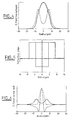
- the graph in FIG. 4 illustrates a mode conversion according to the invention.
- this graph represents the shape of the electric fields of the LP01 modes at the input of the converter (thick line) and at the output of the converter according to the invention (thin line).
- FIG. 5 represents the radial shape of the index profile at the input (thick line) and at output (thin line) of the mode adapter used for the application illustrated in FIG. 4.
- FIG. 6 illustrates the appearance of the electric field of the LP01 mode at the output of the converter of FIG. 4 (thick line), and the appearance of the electric fields of the modes LP01 (dotted lines) and LP02 (thin line) of a fiber of compensation. It can be seen that the mode converter according to the invention makes it possible to carry out a mode conversion by bringing the input form of the LP01 closer to a W shape approaching the form of the LP02 mode.
- a narrowing or widening of the mode can also be carried out gradually along a section of the optical guide of the converter according to the invention by UV irradiation or an appropriate “poling” of the photosensitive zone of the guide.
- FIGS. 4 to 6 illustrate an application in which it has been sought to carry out an injection in the mode of a dispersion-compensating fiber in a higher order mode (for example the LP02 mode) from the fundamental mode originating from a fiber standard index jump.
- the adaptation is thus carried out in two stages: the first stage consists in deconfining the fundamental mode LP01 coming from a standard fiber, in a similar way to the application described with reference to FIGS. 4 and 5; and the second step (FIGS.
- the transformation of the mode LP01 into a mode having a form of W, covering the form of the mode LP02, is carried out starting from an index profile similar to that obtained from the first adapter so as to reduce loss of connections.
- the mode conversion according to the invention can be carried out over a whole given spectral band, for an application to wideband dispersion compensation for example.
- the mode conversion can also be selective in wavelength, for an application to a compensation of mono channel dispersion for example.
- the rare earth doped zone can be distributed in a ring around the core of the fiber.
- it is advantageous to carry out the pumping of the amplifying medium by using a distribution of the pump power which improves the overlap of the pumping beam with the rare earth doped zone and this whatever the position of the ring.
- the rare earth doped zone can be moved away from the center of the fiber without harming the efficiency of the excitation by the pumping beam.
- the pumping beam can be adapted according to the invention by modifying the appearance of the fields of the modes of the optical signals propagating in the amplifying fiber.
- a non-concentric photosensitivity profile can be envisaged, making it possible to carry out mode conversions for non-concentric structures.
- an adaptation between a standard fiber and a photonic crystal fiber can thus be carried out.
- a transformation of the transverse distribution of the mode coming from a laser diode, with an asymmetrical profile can be carried out to make the transverse distribution of the mode symmetrical.
- Such an adiabatic transformation of the mode can be obtained using a mode converter according to the invention having a photosensitivity profile along a single axis.
- the mode converters according to the invention can advantageously be arranged in cascade in order to provide adaptations of complex modal distribution.
- the photosensitive area irradiated so as to induce the index profile specific to the converter according to the invention can be arranged along a section with an extended core of the optical guide or along a section with a cone heart (type ) of the light guide.
Landscapes
- Physics & Mathematics (AREA)
- Engineering & Computer Science (AREA)
- General Physics & Mathematics (AREA)
- Optics & Photonics (AREA)
- Power Engineering (AREA)
- Microelectronics & Electronic Packaging (AREA)
- Optical Integrated Circuits (AREA)
- Optical Couplings Of Light Guides (AREA)
Abstract
Description
- La présente invention concerne la conversion de mode optique dans un guide d'onde optique. Une telle conversion de mode peut être requise lors du couplage d'un guide optique vers un autre composant optique ou lors d'un traitement du signal optique transmis dans un guide optique nécessitant une conversion de mode, tel qu'une compensation de dispersion ou une égalisation de gain, par exemple.
- Un guide optique, tel qu'une fibre optique ou un guide d'onde planaire, est classiquement composé d'un coeur optique, ayant pour fonction de transmettre et éventuellement d'amplifier un signal optique, entouré d'une gaine optique, ayant pour fonction de confiner le signal optique dans le coeur. A cet effet, les indices de réfraction du coeur n1 et de la gaine n2 sont tels que n1>n2. Ainsi, le coeur et la gaine du guide se comportent comme deux guides d'onde concentriques.
- Un signal optique transmis dans un guide optique peut être monomode ou multimode selon la taille du coeur et la nature du guide optique. Le(s) mode(s) de propagation transmis dans un guide optique présente donc des distributions spatiales spécifiques à chaque application.
- Or, selon les applications, il peut être nécessaire d'adapter la taille d'un mode donné lorsqu'un signal optique est couplé d'un premier composant vers un second composant et que les diamètres de coeurs desdits composants ne sont pas identiques et/ou que les distributions transversales des modes de chaque composant ne sont pas identiques.
- L'adaptation de mode pour réaliser un couplage optique sans perte entre deux guides optiques différents a déjà fait l'objet de nombreux développements dans l'art antérieur.
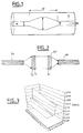
- Ainsi, la solution la plus répandue lorsque le mode doit être élargi consiste à utiliser une technique mise au point par la société NTT, dite TEC pour Thermally Expanded Core en anglais, dont une illustration est donnée sur la figure 1. Cette technique, qui a fait l'objet de brevets japonais (JP 5-330853 et JP 5-312676) consiste à dilater le coeur 10 d'une fibre en la chauffant localement. La chaleur entraîne une diffusion des dopants du coeur 10 vers la gaine 11 de la fibre et provoque un élargissement 12 du diamètre du coeur 10.
- Cette technique a prouvé son efficacité et permet une dilation du coeur d'un facteur deux à trois pour un couplage sans perte mais comporte néanmoins des inconvénients. En particulier, il est nécessaire de chauffer la fibre à environ 1500 °C pendant plusieurs heures et de bien contrôler les paramètres de temps et de température afin de garantir une dilatation adiabatique du coeur qui permette de conserver le caractère monomode du signal transmis sans pertes.
- De plus, la fibre TEC ne permet qu'une expansion du mode de propagation et non une réduction du mode ou une conversion de mode.
- Les autres techniques généralement utilisées pour adapter la taille d'un mode de propagation pour un couplage optique entre composants consistent dans la réalisation d'un taper dans le guide optique ou dans des montages complexes faisant intervenir des fibres lentillées. Un taper peut être réalisé par fusion- étirage de l'extrémité d'une fibre afin de créer une diminution adiabatique du diamètre du coeur et permettre une adaptation de mode sans pertes.
- Les techniques citées, fibres TEC et tapers, sont efficaces pour certaines applications, mais sont limités à des expansions ou réductions de diamètres de mode et ne permettent pas des adaptations plus complexes, avec des guides optiques présentant des géométries différentes, tels que des guides photoniques ou des guides en anneau.
- Une autre technique connue pour adapter la taille d'un mode guidé est décrite dans la publication de Jarvis R A et AI : « Spot size expander using UV trimming of trilayer photosensitive fiber », OECC/IOOC 2001, Confernece Incorporating ACOFT, 2-5 juillet 2001. Cette technique consite à réaliser un profil de photosensibilité qui induit un profil d'indice particulier, permettant en particulier d'élargir la taille du mode optique guidé.
- Les adaptateurs de mode connus décrits précédemment ne permettent pas de réaliser une conversion spatiale du mode de propagation, par exemple pour passer d'un mode de propagation LP01 à LP02. Or, une telle conversion de mode peut trouver des applications, par exemple en entrée d'un réseau à long pas pour une égalisation de gain ou pour une compensation de dispersion chromatique sur des modes d'ordre supérieur.
- Ainsi, en référence à la figure 2, la demande de brevet internationale WO 99/49342 propose de réaliser une conversion de mode optique en insérant des éléments, dits de sélection de phase 74, 74', entre deux guides optiques 54 et 64, ces éléments pouvant comporter des éléments diffractifs ou réflectifs, tels que des lentilles 72, des miroirs, des réseaux, des composants électro-optiques, etc.
- Un tel convertisseur de mode est néanmoins complexe et peu flexible.
- Ces techniques connues de l'art antérieur présentent des limitations que la présente invention écarte.
- L'invention a ainsi pour objet un convertisseur de mode qui permette de réaliser, simultanément, d'une part une modification radiale de la distribution spatiale du mode, et d'autre part une variation longitudinale adiabatique de cette modification radiale du mode.
- A cet effet, l'invention propose de réaliser un profil d'indice spécifique dans une section d'un guide optique au moyen d'un profil de photosensibilité déterminé et contrôlé.
- L'invention concerne plus spécifiquement un convertisseur de mode optique comprenant un guide optique apte à transmettre un signal optique selon au moins un mode guidé, caractérisé en ce que le guide optique comporte une zone photosensible irradiée de façon à induire un profil d'indice spécifique le long d'une section du guide, ledit profile d'indice définissant simultanément une transition adiabatique longitudinale et une distribution transverse du (des) mode(s) guidé(s) de manière à déconfiner le mode fondamental et à maximiser le recouvrement avec un mode d'ordre supérieur.
- Selon les modes de réalisation, le profil d'indice est induit de façon permanente par irradiation ou de façon reconfigurable par «poling» optique de la zone photosensible.
- Selon les applications, la zone photosensible est située dans le coeur et/ou la gaine du guide optique ou est disposée en anneau dans le guide optique.
- Selon une caractéristique, la zone photosensible est dopée avec du Germanium.
- Selon les modes de mise en oeuvre, le guide optique est monomode ou multimode et peut être constitué d'une fibre optique ou d'un guide d'onde planaire.
- Selon les applications, la transition adiabatique de la distribution transverse du mode guidé introduit en outre un élargissement ou un rétrécissement du diamètre dudit mode ou.
- Selon les applications, la conversion de mode peut être effectuée sur toute une bande spectrale donnée ou être sélective en longueur d'onde.
- Selon les modes de réalisation, la zone photosensible irradiée de façon à induire un profil d'indice spécifique peut être disposée le long d'une section à coeur en cône du guide optique ou le long d'une section à coeur étendu du guide optique
- Les particularités et avantages de l'invention ressortiront plus clairement à la lecture de la description qui suit, faite à titre d'exemple illustratif et non limitatif, en référence aux figures annexées dans lesquelles :
- la figure 1, déjà décrite, illustre schématiquement une technique d'adaptation de mode connue de l'art antérieur ;
- la figure 2, déjà décrite, illustre schématiquement une technique de conversion de mode connue de l'art antérieur ;
- la figure 3 illustre schématiquement un profil d'indice dans un adaptateur de mode selon l'invention ;
- la figure 4 est un graphe illustrant l'allure des champs électriques des modes LP01 en entrée et sortie dans une deuxième application de l'adaptateur selon l'invention ;
- la figure 5 est un graphe illustrant le profil d'indice radial en entrée et sortie de l'adaptateur de la figure 6 ;
- la figure 6 est un graphe illustrant l'allure du champ électrique du mode LP01 en sortie de l'adaptateur de la figure 6, et l'allure des champs électriques des modes LP01 et LP02 d'une fibre de compensation.
- L'objectif de la présente invention est de réaliser une modification radiale du profil d'indice dans un guide optique et de changer ainsi la distribution spatiale d'au moins un mode de propagation dans ledit guide optique avec une transition longitudinale adiabatique. L'invention peut s'appliquer à un quelconque guide optique, tel qu'un guide planaire ou une fibre optique, qu'il s'agisse d'un guide d'onde monomode ou multimode.
- Cette modification de la distribution spatiale d'au moins un mode de propagation consiste en une conversion de mode, éventuellement combinée avec une variation de l'étalement du mode (élargissement ou réduction).
- En référence à la figure 3, on nomme arbitrairement z l'axe dit longitudinal selon lequel se propage un signal optique dans le guide et r l'axe dit radial selon lequel est distribué le mode de propagation transmis.
- Le guide optique du convertisseur selon l'invention présente une zone photosensible obtenue par dopage des matériaux constituant le guide, par exemple avec du Germanium.
- On peut alors établir la relation suivante exprimant le profil d'indice du guide optique :

- n(r,z) l'indice du guide optique en un point donné
- nint l'indice intrinsèque du guide
- PS(r) le profil normalisé de photosensibilité du guide (0<PS(r)<1)
- FUV(z) la fonction d'irradiation longitudinale de la zone photosensible du guide (0<FUV(z)<max, avec FUV(z)=max correspondant à l'irradiation maximum entraînant une modification maximale de l'indice au point z donné.
- Ainsi, par une irradiation contrôlée de la zone photosensible du guide, il est possible de modifier localement et très précisément l'indice de réfraction du guide. La variation radiale du profil d'indice permet d'atteindre la conversion de mode recherchée et le contrôle précis de l'irradiation le long du guide permet en particulier d'assurer une transition longitudinale adiabatique de la variation radiale.
- Selon les applications, le profil d'indice peut être défini de manière permanente ou reconfigurable dans une section du guide d'onde de l'adaptateur de mode selon l'invention.
- La zone photosensible peut être irradiée par exposition à des rayons UV et définir ainsi un profil d'indice donné permanent.
- Un profil d'indice donné peut également être induit de façon reconfigurable. Une méthode envisageable pour réaliser un tel profil d'indice consiste dans une méthode dite de « poling » optique. La méthode de « poling» consiste à créer, au sein du matériau dont l'indice de réfraction doit être modifié, une direction et un sens privilégié qui augmentent la susceptibilité non-linéaire d'ordre 2. La zone photosensible du guide est donc insolée et un champ électrique est appliqué simultanément sur ladite zone. La commande des électrodes générant le champ électrique permet de déterminer la variation d'indice et de créer ainsi un profil d'indice reconfigurable.
- Le graphe de la figure 4 illustre une conversion de mode selon l'invention. En particulier, ce graphe représente l'allure des champs électriques des modes LP01 en entrée du convertisseur (trait épais) et en sortie du convertisseur selon l'invention (trait fin).
- La figure 5 représente l'allure radiale du profil d'indice en entrée (trait épais) et en sortie (trait fin) de l'adaptateur de mode utilisé pour l'application illustré sur la figure 4 .
- La figure 6 illustre l'allure du champ électrique du mode LP01 en sortie du convertisseur de la figure 4 (trait épais), et l'allure des champs électriques des modes LP01 (pointillés) et LP02 (trait fin) d'une fibre de compensation. On constate que le convertisseur de mode selon l'invention permet d'effectuer une conversion de mode en rapprochant la forme en entrée du LP01 à une forme en W se rapprochant de la forme du mode LP02.
- Selon l'invention, un rétrécissement ou un élargissement du mode peut également être conduit progressivement le long d'une section du guide optique du convertisseur selon l'invention par une irradiation UV ou un « poling » approprié de la zone photosensible du guide.Les figures 4 à 6 illustrent une application dans laquelle on a cherché à réaliser une injection dans le mode d'une fibre compensatrice de dispersion sur un mode d'ordre supérieur (par exemple le mode LP02) à partir du mode fondamental issu d'une fibre standard à saut d'indice. L'adaptation s'effectue ainsi en deux étapes : la première étape consiste à déconfiner le mode fondamental LP01 issu d'une fibre standard, de manière similaire à l'application décrite en référence aux figures 4 et 5 ; et la seconde étape (figures 6 à 8) consiste à mettre en forme le mode LP01 ainsi obtenu pour maximiser le recouvrement avec le mode d'ordre supérieur transmis par la fibre compensatrice (LP02). La transformation du mode LP01 en un mode présentant une forme de W, recouvrant la forme du mode LP02, est réalisée en partant d'un profil d'indice similaire à celui obtenu en sorti du premier adaptateur de manière à diminuer les pertes de connexions.
- Selon les applications, la conversion de mode selon l'invention peut être effectuée sur toute une bande spectrale donnée, pour une application à une compensation de dispersion large bande par exemple. La conversion de mode peut également être sélective en longueur d'onde, pour une application à une compensation de dispersion mono canal par exemple.
- D'autres exemples d'applications peuvent être envisagés pour le convertisseur de mode selon l'invention, selon le même principe que précédemment décrit, afin de réaliser une quelconque modification de la forme d'un mode de propagation d'un signal optique.
- En particulier, dans le domaine des fibres amplificatrices, dites EDFA pour Erbium Doped Fiber Amplifier en anglais, la zone dopée terre rare peut être répartie en anneau autour du coeur de la fibre. Dans une structure à pompage par la gaine, il est intéressant de réaliser le pompage du milieu amplificateur en utilisant une répartition de la puissance de pompe qui améliore le recouvrement du faisceau de pompage avec la zone dopée terre rare et ce quelle que soit la position de l'anneau.
- Ainsi, la zone dopée terre rare peut être éloignée du centre de la fibre sans nuire à l'efficacité de l'excitation par le faisceau de pompage. En effet, le faisceau de pompage peut être adapté selon l'invention par une modification de l'allure des champs des modes des signaux optiques se propageant dans la fibre amplificatrice.
- De même, un profil de photosensibilité non-concentrique peut être envisagé, permettant de réaliser des conversions de mode pour des structures non concentriques. Par exemple, une adaptation entre une fibre standard et une fibre à cristaux photoniques peut ainsi être réalisée.
- Dans un autre exemple, une transformation de la distribution transverse du mode issu d'une diode laser, avec un profil dissymétrique, peut être réalisée pour rendre la distribution transverse du mode symétrique. Une telle transformation adiabatique du mode peut être obtenue à l'aide d'un convertisseur de mode selon l'invention ayant un profil de photosensibilité suivant un seul axe.
- Les convertisseurs de mode selon l'invention peuvent avantageusement être disposés en cascade afin de fournir des adaptations de distribution modale complexes.
- On peut également envisager de combiner avantageusement les effets du convertisseur de mode selon l'invention avec des adaptateurs dits classiques mentionnés en référence à l'art antérieur. Ainsi, la zone photosensible irradiée de façon à induire le profil d'indice spécifique au convertisseur selon l'invention peut être disposée le long d'une section à coeur étendu du guide optique ou le long d'une section à coeur en cône (taper) du guide optique.
Claims (15)
- Convertisseur de mode optique comprenant un guide optique apte à transmettre un signal optique selon au moins un mode guidé, caractérisé en ce que le guide optique comporte une zone photosensible irradiée de façon à induire un profil d'indice spécifique le long d'une section du guide, ledit profil d'indice définissant simultanément une transition adiabatique longitudinale et une distribution transverse du (des) mode(s) guidé(s) de manière à déconfiner le mode fondamental et à maximiser le recouvrement avec un mode d'ordre supérieur.
- Convertisseur de mode selon la revendication 1, caractérisé en ce que le profil d'indice est induit de façon permanente par irradiation de la zone photosensible.
- Convertisseur de mode selon la revendication 1, caractérisé en ce que le profil d'indice est induit de façon reconfigurable par « poling » optique sur la zone photosensible.
- Convertisseur de mode selon l'une des revendications précédentes, caractérisé en ce que la zone photosensible est située dans le coeur et/ou la gaine du guide optique.
- Convertisseur de mode selon l'une des revendications précédentes, caractérisé en ce que la zone photosensible est disposée en anneau dans le guide optique.
- Convertisseur de mode selon l'une des revendications précédentes, caractérisé en ce que la zone photosensible est dopée avec du Germanium.
- Convertisseur de mode selon l'une des revendications 1 à 6, caractérisé en ce que le guide optique est un guide monomode.
- Convertisseur de mode selon l'une des revendications 1 à 6, caractérisé en ce que le guide optique est un guide multimode.
- Convertisseur de mode selon l'une des revendications 1 à 8, caractérisé en ce que le guide optique est une fibre optique.
- Convertisseur de mode selon l'une des revendications 1 à 8, caractérisé en ce que le guide optique est un guide d'onde planaire.
- Convertisseur de mode selon l'une des revendications précédentes, caractérisé en ce que la transition adiabatique de la distribution transverse du mode guidé induit en outre un élargissement ou un rétrécissement du diamètre dudit mode.
- Convertisseur de mode selon l'une des revendications 1 à 11, caractérisé en ce que la conversion de mode est effectuée sur toute une bande spectrale donnée.
- Convertisseur de mode selon l'une des revendications 1 à 11, caractérisé en ce que la conversion de mode est sélective en longueur d'onde.
- Convertisseur de mode selon l'une des revendications précédentes, caractérisé en ce que la zone photosensible irradiée de façon à induire un profil d'indice spécifique est disposée le long d'une section à coeur en cône du guide optique.
- Convertisseur de mode selon l'une des revendications précédentes, caractérisé en ce que la zone photosensible irradiée de façon à induire un profil d'indice spécifique est disposée le long d'une section à coeur étendu du guide optique.
Applications Claiming Priority (2)
| Application Number | Priority Date | Filing Date | Title |
|---|---|---|---|
| FR0202702 | 2002-03-04 | ||
| FR0202702A FR2836725A1 (fr) | 2002-03-04 | 2002-03-04 | Adaptateur de mode optique |
Publications (1)
| Publication Number | Publication Date |
|---|---|
| EP1343031A1 true EP1343031A1 (fr) | 2003-09-10 |
Family
ID=27741416
Family Applications (1)
| Application Number | Title | Priority Date | Filing Date |
|---|---|---|---|
| EP03290509A Withdrawn EP1343031A1 (fr) | 2002-03-04 | 2003-03-04 | Convertisseur de mode optique |
Country Status (3)
| Country | Link |
|---|---|
| US (1) | US6937789B2 (fr) |
| EP (1) | EP1343031A1 (fr) |
| FR (1) | FR2836725A1 (fr) |
Cited By (1)
| Publication number | Priority date | Publication date | Assignee | Title |
|---|---|---|---|---|
| EP1950589A1 (fr) * | 2007-01-25 | 2008-07-30 | Furukawa Electric North America, Inc. | Dispositifs de fibre optique et procédé d'interconnexion de fibres différentes |
Families Citing this family (5)
| Publication number | Priority date | Publication date | Assignee | Title |
|---|---|---|---|---|
| FR2875016B1 (fr) * | 2004-09-08 | 2006-11-24 | Cit Alcatel | Convertisseur de mode |
| US8255267B2 (en) * | 2007-07-13 | 2012-08-28 | Wahrheit, Llc | System and method for determining relative preferences |
| US20110293215A1 (en) * | 2010-03-30 | 2011-12-01 | Anthony Ruggiero | Low loss laser transmission through telescopes with mirror obscurations |
| ES2966910T3 (es) | 2014-03-25 | 2024-04-25 | Nkt Photonics As | Una fuente de generación de supercontinuo óptico que comprende una fibra óptica microestructurada |
| CN109725386B (zh) * | 2018-12-24 | 2023-08-29 | 云南大学 | 多波段的宽带光波导模式转换器 |
Citations (1)
| Publication number | Priority date | Publication date | Assignee | Title |
|---|---|---|---|---|
| WO2001059496A2 (fr) * | 2000-02-07 | 2001-08-16 | Corning Incorporated | Module de compensation de dispersion et convertisseur de mode, coupleur et guide d'ondes optique de compensation de dispersion |
Family Cites Families (3)
| Publication number | Priority date | Publication date | Assignee | Title |
|---|---|---|---|---|
| UA47454C2 (uk) * | 1996-12-20 | 2002-07-15 | Научний Центр Волоконной Оптікі Прі Інстітутє Общєй Фізікі Россійской Акадєміі Наук | Волоконний конвертор діаметра поля моди, спосіб локальної зміни показника заломлення оптичних хвильоводів та спосіб виготовлення заготівок для оптичних хвильоводів |
| KR100333900B1 (ko) * | 1999-01-21 | 2002-04-24 | 윤종용 | 모드모양 변환기, 그 제작 방법 및 이를 구비한 집적광학 소자 |
| US20040114869A1 (en) * | 2001-06-15 | 2004-06-17 | Fike Eugene E. | Mode converter including tapered waveguide for optically coupling photonic devices |
-
2002
- 2002-03-04 FR FR0202702A patent/FR2836725A1/fr active Pending
-
2003
- 2003-03-04 EP EP03290509A patent/EP1343031A1/fr not_active Withdrawn
- 2003-03-04 US US10/377,874 patent/US6937789B2/en not_active Expired - Fee Related
Patent Citations (1)
| Publication number | Priority date | Publication date | Assignee | Title |
|---|---|---|---|---|
| WO2001059496A2 (fr) * | 2000-02-07 | 2001-08-16 | Corning Incorporated | Module de compensation de dispersion et convertisseur de mode, coupleur et guide d'ondes optique de compensation de dispersion |
Non-Patent Citations (9)
| Title |
|---|
| FRISKEN S J: "LIGHT-INDUCED OPTICAL WAVEGUIDE UPTAPERS", OPTICS LETTERS, OPTICAL SOCIETY OF AMERICA, WASHINGTON, US, vol. 18, no. 13, 1 July 1993 (1993-07-01), pages 1035 - 1037, XP000372731, ISSN: 0146-9592 * |
| FUJIWARA T ET AL: "Electro-optic modulation in germanosilicate fibre with UV-excited poling", ELECTRONICS LETTERS, IEE STEVENAGE, GB, vol. 31, no. 7, 30 March 1995 (1995-03-30), pages 573 - 575, XP006002642, ISSN: 0013-5194 * |
| JARVIS R A ET AL: "Bend-radius reduction in planar waveguides using UV post-tuning", ELECTRONICS LETTERS, IEE STEVENAGE, GB, vol. 33, no. 10, 8 May 1997 (1997-05-08), pages 892 - 894, XP006007473, ISSN: 0013-5194 * |
| JARVIS R A ET AL: "Spot size expander using UV-trimming of trilayer photosensitive fibres", CONFERENCE PROCEEDINGS. OECC/IOOC 2001 CONFERENCE. INCORPORATING ACOFT, PROCEEDINGS OECC.IOOC 2001: OPTOELECTRONICS AND COMMUNICATIONS CONFERENCE INTEGRATED OPTICS AND OPTICAL FIBER COMMUNICATIONS, SYDNEY, NSW, AUSTRALIA, 1-5 JULY 2001, 2001, Sydney, NSW, Australia, OECC/IOOC 2001 Conference, Australia, pages 408 - 409, XP008012225, ISBN: 0-646-41752-5 * |
| JIN X: "OPTICAL FIBER INDEX TAPER-THEORETICAL ANALYSIS AND EXPERIMENT DEMONSTRATION", INTERNATIONAL JOURNAL OF INFRARED AND MILLIMETER WAVES, PLENUM PUBLISHING, NEW YORK, US, vol. 19, no. 6, 1 June 1998 (1998-06-01), pages 875 - 886, XP000766207, ISSN: 0195-9271 * |
| KY N H ET AL: "EFFICIENT BROADBAND INTRACORE GRATING LP01-LP02 MODE CONVERTERS FOR CHROMATIC-DISPERSION COMPENSATION", OPTICS LETTERS, OPTICAL SOCIETY OF AMERICA, WASHINGTON, US, vol. 23, no. 6, 15 March 1998 (1998-03-15), pages 445 - 447, XP000753367, ISSN: 0146-9592 * |
| LJUNGSTROM A M ET AL: "Light-induced self-writing effects in bulk chalcogenide glass", JOURNAL OF LIGHTWAVE TECHNOLOGY, JAN. 2002, IEEE, USA, vol. 20, no. 1, pages 78 - 85, XP002226454, ISSN: 0733-8724 * |
| POULSEN CHRISTIAN V ET AL: "Photosensitivity in germania-doped silica films", PROCEEDINGS OF THE 1994 CONFERENCE ON LASERS AND ELECTRO-OPTICS EUROPE;AMSTERDAM, NETH AUG 28-SEP 2 1994, 1994, Conf Lasers Electro Opt Eur Tech Dig;Conference on Lasers and Electro-Optics Europe - Technical Digest 1994 IEEE, Piscataway, NJ, USA, XP002226455 * |
| SVALGAARD M ET AL: "Direct UV writing of buried singlemode channel waveguides in Ge-doped silica films", ELECTRONICS LETTERS, IEE STEVENAGE, GB, vol. 30, no. 17, 18 August 1994 (1994-08-18), pages 1401 - 1403, XP006000929, ISSN: 0013-5194 * |
Cited By (2)
| Publication number | Priority date | Publication date | Assignee | Title |
|---|---|---|---|---|
| EP1950589A1 (fr) * | 2007-01-25 | 2008-07-30 | Furukawa Electric North America, Inc. | Dispositifs de fibre optique et procédé d'interconnexion de fibres différentes |
| CN101231368B (zh) * | 2007-01-25 | 2012-10-10 | 古河电子北美公司 | 用于互连不同光纤的光纤设备和方法 |
Also Published As
| Publication number | Publication date |
|---|---|
| FR2836725A1 (fr) | 2003-09-05 |
| US20030165289A1 (en) | 2003-09-04 |
| US6937789B2 (en) | 2005-08-30 |
Similar Documents
| Publication | Publication Date | Title |
|---|---|---|
| US6301421B1 (en) | Photonic crystal fiber lasers and amplifiers for high power | |
| EP1482606B1 (fr) | Fibre optique pour amplification ou pour émission laser | |
| JP2008276233A (ja) | 光ファイバ中でのモードフィールドのサイズ変更 | |
| FR2834347A1 (fr) | Coupleur optique pour pompe multimode | |
| FR2533034A1 (fr) | Derivation pour fibre optique | |
| EP0793124B1 (fr) | Filtre obtenu par inscription d'un réseau de Bragg dans une fibre optique | |
| FR2706633A1 (fr) | Dispositif optique comportant une fibre optique amorce et procédé pour sa fabrication. | |
| FR2756054A1 (fr) | Coupleur optique a evolution modale et procede pour sa fabrication | |
| WO2005003829A1 (fr) | Fibre optique multimode | |
| EP0992817A1 (fr) | Fibre optique monomode à dispersion décalée à grande aire effective | |
| EP1343031A1 (fr) | Convertisseur de mode optique | |
| FR2629219A1 (fr) | Coupleur de fibres optiques en etoile et de type actif | |
| EP2823342B1 (fr) | Dispositif de conversion du profil spatial transverse d'intensite d'un faisceau lumineux, utilisant de preference une fibre optique microstructuree | |
| EP2041848B1 (fr) | Dispositif laser à fibre optique de puissance | |
| CA2297558C (fr) | Systeme, ligne et procede de transmission a fibre optique | |
| FR3108412A1 (fr) | Guide d’onde multimode configuré pour générer une radiation monomode à partir d’une radiation monomode. | |
| EP1455425A1 (fr) | Fibre optique amplificatrice à anneau dope et amplificateur contenant une telle fibre | |
| FR2856482A1 (fr) | Filtre optique | |
| FR2929456A1 (fr) | Systeme a fibre laser de forte puissance. | |
| FR2805899A1 (fr) | Amplification optique a fibre a gaine multimode en bande c | |
| EP0637109B1 (fr) | Amplificateur optique à fibre optique en verre fluoré dopé et procédé de fabrication de cet amplificateur | |
| FR3016742A1 (fr) | Dispositif d'amplification optique multimode | |
| FR2635876A1 (fr) | Fibre optique monomode protegee contre le detournement d'informations transmises et procede de transmission utilisant cette fibre | |
| EP1030412B1 (fr) | Amplificateur optique | |
| FR2756055A1 (fr) | Coupleur optique multimodes et procede pour sa fabrication |
Legal Events
| Date | Code | Title | Description |
|---|---|---|---|
| PUAI | Public reference made under article 153(3) epc to a published international application that has entered the european phase |
Free format text: ORIGINAL CODE: 0009012 |
|
| AK | Designated contracting states |
Kind code of ref document: A1 Designated state(s): AT BE BG CH CY CZ DE DK EE ES FI FR GB GR HU IE IT LI LU MC NL PT RO SE SI SK TR |
|
| AX | Request for extension of the european patent |
Extension state: AL LT LV MK |
|
| RAP1 | Party data changed (applicant data changed or rights of an application transferred) |
Owner name: AVANEX CORPORATION |
|
| RIN1 | Information on inventor provided before grant (corrected) |
Inventor name: RIANT, ISABELLE Inventor name: LECLERE, CHRISTELLE Inventor name: MOLINA, MARIANNE Inventor name: PROVOST, LIONEL Inventor name: DE BARROS, CARLOS |
|
| 17P | Request for examination filed |
Effective date: 20040223 |
|
| AKX | Designation fees paid |
Designated state(s): AT BE BG CH CY CZ DE DK EE ES FI FR GB GR HU IE IT LI LU MC NL PT RO SE SI SK TR |
|
| 17Q | First examination report despatched |
Effective date: 20040507 |
|
| STAA | Information on the status of an ep patent application or granted ep patent |
Free format text: STATUS: THE APPLICATION IS DEEMED TO BE WITHDRAWN |
|
| 18D | Application deemed to be withdrawn |
Effective date: 20040908 |