EP1343003A2 - Gas sensor - Google Patents
Gas sensor Download PDFInfo
- Publication number
- EP1343003A2 EP1343003A2 EP03251312A EP03251312A EP1343003A2 EP 1343003 A2 EP1343003 A2 EP 1343003A2 EP 03251312 A EP03251312 A EP 03251312A EP 03251312 A EP03251312 A EP 03251312A EP 1343003 A2 EP1343003 A2 EP 1343003A2
- Authority
- EP
- European Patent Office
- Prior art keywords
- detection element
- gas sensor
- detection
- housing
- flow path
- Prior art date
- Legal status (The legal status is an assumption and is not a legal conclusion. Google has not performed a legal analysis and makes no representation as to the accuracy of the status listed.)
- Withdrawn
Links
- 238000001514 detection method Methods 0.000 claims abstract description 198
- 239000000945 filler Substances 0.000 claims abstract description 28
- 229910052751 metal Inorganic materials 0.000 claims description 18
- 239000002184 metal Substances 0.000 claims description 18
- 230000002238 attenuated effect Effects 0.000 claims description 12
- 229920003002 synthetic resin Polymers 0.000 claims description 4
- 239000000057 synthetic resin Substances 0.000 claims description 4
- 238000005192 partition Methods 0.000 claims description 3
- 238000005259 measurement Methods 0.000 abstract description 44
- 230000001681 protective effect Effects 0.000 abstract description 17
- 239000010410 layer Substances 0.000 description 76
- 230000002829 reductive effect Effects 0.000 description 29
- RYGMFSIKBFXOCR-UHFFFAOYSA-N Copper Chemical compound [Cu] RYGMFSIKBFXOCR-UHFFFAOYSA-N 0.000 description 25
- 239000011889 copper foil Substances 0.000 description 23
- 238000002474 experimental method Methods 0.000 description 23
- 230000005540 biological transmission Effects 0.000 description 20
- 239000000758 substrate Substances 0.000 description 17
- XUIMIQQOPSSXEZ-UHFFFAOYSA-N Silicon Chemical compound [Si] XUIMIQQOPSSXEZ-UHFFFAOYSA-N 0.000 description 15
- 229910052710 silicon Inorganic materials 0.000 description 15
- 239000010703 silicon Substances 0.000 description 15
- 239000006260 foam Substances 0.000 description 13
- 239000000463 material Substances 0.000 description 13
- 230000008859 change Effects 0.000 description 11
- 238000003780 insertion Methods 0.000 description 11
- 230000037431 insertion Effects 0.000 description 11
- 229920000139 polyethylene terephthalate Polymers 0.000 description 11
- 239000005020 polyethylene terephthalate Substances 0.000 description 11
- -1 Polyethylene terephthalate Polymers 0.000 description 10
- 239000000853 adhesive Substances 0.000 description 9
- 230000001070 adhesive effect Effects 0.000 description 9
- JOYRKODLDBILNP-UHFFFAOYSA-N Ethyl urethane Chemical compound CCOC(N)=O JOYRKODLDBILNP-UHFFFAOYSA-N 0.000 description 8
- 238000000034 method Methods 0.000 description 6
- 238000002485 combustion reaction Methods 0.000 description 5
- 230000007423 decrease Effects 0.000 description 5
- 230000002093 peripheral effect Effects 0.000 description 5
- 238000010926 purge Methods 0.000 description 4
- 230000009467 reduction Effects 0.000 description 4
- 230000035945 sensitivity Effects 0.000 description 4
- 230000035882 stress Effects 0.000 description 4
- 230000008646 thermal stress Effects 0.000 description 4
- 230000009471 action Effects 0.000 description 3
- 239000012790 adhesive layer Substances 0.000 description 3
- 239000000919 ceramic Substances 0.000 description 3
- 238000004891 communication Methods 0.000 description 3
- 230000000694 effects Effects 0.000 description 3
- 239000011521 glass Substances 0.000 description 3
- 238000012545 processing Methods 0.000 description 3
- 229920005989 resin Polymers 0.000 description 3
- 239000011347 resin Substances 0.000 description 3
- 229920002803 thermoplastic polyurethane Polymers 0.000 description 3
- 238000003466 welding Methods 0.000 description 3
- 229920002799 BoPET Polymers 0.000 description 2
- OKTJSMMVPCPJKN-UHFFFAOYSA-N Carbon Chemical compound [C] OKTJSMMVPCPJKN-UHFFFAOYSA-N 0.000 description 2
- 229910052782 aluminium Inorganic materials 0.000 description 2
- XAGFODPZIPBFFR-UHFFFAOYSA-N aluminium Chemical compound [Al] XAGFODPZIPBFFR-UHFFFAOYSA-N 0.000 description 2
- 229910052799 carbon Inorganic materials 0.000 description 2
- 229910052802 copper Inorganic materials 0.000 description 2
- 239000010949 copper Substances 0.000 description 2
- 229920001971 elastomer Polymers 0.000 description 2
- 239000000446 fuel Substances 0.000 description 2
- 238000002347 injection Methods 0.000 description 2
- 239000007924 injection Substances 0.000 description 2
- 239000003921 oil Substances 0.000 description 2
- 238000005476 soldering Methods 0.000 description 2
- XLYOFNOQVPJJNP-UHFFFAOYSA-N water Chemical compound O XLYOFNOQVPJJNP-UHFFFAOYSA-N 0.000 description 2
- 239000004593 Epoxy Substances 0.000 description 1
- VYPSYNLAJGMNEJ-UHFFFAOYSA-N Silicium dioxide Chemical compound O=[Si]=O VYPSYNLAJGMNEJ-UHFFFAOYSA-N 0.000 description 1
- 230000015572 biosynthetic process Effects 0.000 description 1
- 239000003990 capacitor Substances 0.000 description 1
- 239000013078 crystal Substances 0.000 description 1
- 230000003247 decreasing effect Effects 0.000 description 1
- 238000010586 diagram Methods 0.000 description 1
- 238000007599 discharging Methods 0.000 description 1
- 239000003822 epoxy resin Substances 0.000 description 1
- 238000005530 etching Methods 0.000 description 1
- 230000008020 evaporation Effects 0.000 description 1
- 238000001704 evaporation Methods 0.000 description 1
- WABPQHHGFIMREM-UHFFFAOYSA-N lead(0) Chemical compound [Pb] WABPQHHGFIMREM-UHFFFAOYSA-N 0.000 description 1
- 239000000203 mixture Substances 0.000 description 1
- 238000012986 modification Methods 0.000 description 1
- 230000004048 modification Effects 0.000 description 1
- 238000012544 monitoring process Methods 0.000 description 1
- 238000000465 moulding Methods 0.000 description 1
- 229920000647 polyepoxide Polymers 0.000 description 1
- 230000001902 propagating effect Effects 0.000 description 1
- 230000002441 reversible effect Effects 0.000 description 1
- 239000011034 rock crystal Substances 0.000 description 1
- 238000005096 rolling process Methods 0.000 description 1
- 230000002123 temporal effect Effects 0.000 description 1
- 230000007704 transition Effects 0.000 description 1
- 238000007740 vapor deposition Methods 0.000 description 1
Images









Classifications
-
- G—PHYSICS
- G01—MEASURING; TESTING
- G01N—INVESTIGATING OR ANALYSING MATERIALS BY DETERMINING THEIR CHEMICAL OR PHYSICAL PROPERTIES
- G01N29/00—Investigating or analysing materials by the use of ultrasonic, sonic or infrasonic waves; Visualisation of the interior of objects by transmitting ultrasonic or sonic waves through the object
- G01N29/02—Analysing fluids
-
- G—PHYSICS
- G01—MEASURING; TESTING
- G01N—INVESTIGATING OR ANALYSING MATERIALS BY DETERMINING THEIR CHEMICAL OR PHYSICAL PROPERTIES
- G01N29/00—Investigating or analysing materials by the use of ultrasonic, sonic or infrasonic waves; Visualisation of the interior of objects by transmitting ultrasonic or sonic waves through the object
- G01N29/02—Analysing fluids
- G01N29/032—Analysing fluids by measuring attenuation of acoustic waves
-
- G—PHYSICS
- G01—MEASURING; TESTING
- G01N—INVESTIGATING OR ANALYSING MATERIALS BY DETERMINING THEIR CHEMICAL OR PHYSICAL PROPERTIES
- G01N29/00—Investigating or analysing materials by the use of ultrasonic, sonic or infrasonic waves; Visualisation of the interior of objects by transmitting ultrasonic or sonic waves through the object
- G01N29/22—Details, e.g. general constructional or apparatus details
- G01N29/222—Constructional or flow details for analysing fluids
-
- G—PHYSICS
- G01—MEASURING; TESTING
- G01N—INVESTIGATING OR ANALYSING MATERIALS BY DETERMINING THEIR CHEMICAL OR PHYSICAL PROPERTIES
- G01N2291/00—Indexing codes associated with group G01N29/00
- G01N2291/02—Indexing codes associated with the analysed material
- G01N2291/021—Gases
- G01N2291/0217—Smoke, combustion gases
-
- G—PHYSICS
- G01—MEASURING; TESTING
- G01N—INVESTIGATING OR ANALYSING MATERIALS BY DETERMINING THEIR CHEMICAL OR PHYSICAL PROPERTIES
- G01N2291/00—Indexing codes associated with group G01N29/00
- G01N2291/02—Indexing codes associated with the analysed material
- G01N2291/028—Material parameters
- G01N2291/02809—Concentration of a compound, e.g. measured by a surface mass change
Definitions
- the present invention relates to a gas sensor, and more specifically relates to a gas sensor which is provided facing a predetermined flow path of a gas and includes a detection element for receiving a predetermined signal to vibrate and detecting means which transmits a vibration wave generated by the vibration of the detection element in a flow path direction to detect characteristics of a gas.
- a gas sensor which detects characteristics, for example, a concentration, a temperature, or a humidity, of a specific component of a gas existing in a flow path, using a detection element.
- a signal from the detection element is electrically processed and outputted as an electric signal corresponding to the characteristics of the gas.
- a gas concentration sensor which is provided in transportation equipment mounted with an internal combustion engine such as an automobile and detects a concentration of gasoline, gas oil, or the like utilizing a change in a propagation speed of a vibration wave of sound will be discussed.
- Such a gas sensor is arranged, for example, in a passage for purging gasoline from a canister mounted on the automobile to an inlet pipe of the internal combustion engine.
- the gas concentration sensor includes a flow path of a predetermined volume through which a gas containing gasoline vapor in the above-described passage flows and a detection element which is provided facing this flow path and detects a gas concentration.
- the gas concentration sensor vibrates the detection element in detecting the gas concentration and transmits a vibration wave (e.g., ultrasonic wave) generated by this vibration in a flow path direction.
- a vibration wave which is transmitted in the flow path direction of the gas from the detection element by the detection element vibrating for detection of the gas concentration is hereinafter referred to as a vibration wave for detection.
- a speed of the vibration wave passing through the flow path changes according to a concentration of gasoline vapor existing in the flow paths
- the gas concentration sensor detects a speed of the vibration wave for detection passing through a flow path of a fixed flow path length with a receiver for receiving the vibration wave for detection, finds the concentration of the gasoline vapor from a result of this detection, and outputs it.
- the detection element for transmitting the vibration wave for detection is arranged in a housing which is formed of resin or the like with high heat resistance (e.g., see JP-A-2000-206099).
- a filled layer is formed by filling a filler such as urethane in the housing, in which the detection element is arranged, to seal the detection element and regulate a positional movement of the detection element.
- a reverberation may occur in a filled layer in which the detection element is embedded following vibration of the detection element, and as the detection element is affected by this reverberation, it is likely that characteristics of a gas such as a gas concentration cannot be detected accurately.
- noise vibration wave a vibration wave emitted in the direction different from the transmission direction of the vibration wave for detection by vibration of the detection element affected by this reverberation
- the detection element for transmission and the detection element for reception are provided separately, it is also likely that, if a reverberation in the filled layer lasts long, after a vibration wave for detection is transmitted to a gas flow path, a noise vibration wave is transmitted to the gas flow path from the detection element affected by the reverberation, and accuracy of detection of a gas concentration based upon the vibration wave for detection falls.
- a characteristic is observed that such a reverberation is continued over a longer period under a higher temperature. Therefore, under an environment in which temperature tends to increase such as in the vicinity of a passage for purging gasoline or a gas flow path in the gas sensor, a reverberation may increase to make accurate detection of a gas concentration difficult.
- the present invention adopts a structure as described below for the purpose of solving at least one of the above-described problems and providing a gas sensor which is capable of detecting a gas concentration accurately under high temperature.
- a gas sensor of the present invention is a gas sensor including a detection element which is provided facing a predetermined flow path of a gas and receives a predetermined signal to vibrate and detecting means which transmits a vibration wave, which is generated by the vibration of the detection element in the flow path direction, as a vibration wave for detection to detect characteristics of the gas, characterized by comprising:
- the element for transmitting a vibration wave for detection in a flow path direction of a gas according to vibration and an attenuation member with which vibration wave (noise vibration wave) emitted in a direction different from a transmission direction of the vibration wave for detection collides to have an energy thereof attenuated are provided in the housing, and the filled layer is formed by filling the predetermined filler at least up to a position where the detection element is embedded in the housing.
- the attenuation member is preferably set in a propagation route of noise vibration wave to be emitted in term of increasing certainty of collision with the noise vibration wave.
- a set position of the attenuation member a position surrounding the detection element between the housing and the detection element, a surface of the detection element opposed to a surface of the filled layer, and the like are possible.
- the attenuation member set in the former position is hereinafter referred to as an intervening member and the attenuation member set in the latter position is hereinafter referred to as a surface member.
- a structure in which one of the intervening member and the surface member is set may be adopted or a structure in which both the intervening member and the surface member are set may be adopted. It is needless to mention that it is also possible to set the attenuation member in a position other than the above-mentioned position cited as an example.
- the intervening member is provided as the attenuation member, since the energy of a noise vibration wave emitted in a direction of an internal peripheral surface of the housing is attenuated by collision with the intervening member, a reverberation generated in the filled layer can be reduced promptly.
- this intervening member surrounds the entire periphery of the detection element, an attenuation efficiency of reverberation can be further increased.
- the intervening member is constituted by using a medium having a larger density than the filler on the detection element side.
- a structure is possible in which the medium used in the housing side is synthetic resin and the medium used on the detection element side is a metal.
- the intervening member In the case in which a metal is used on the detection element side of the intervening member, it is preferable to make this metal not adhered to the filled layer. In this way, since a metal surface of the intervening member is allowed to slide against the filled layer, a thermal stress generated in the periphery of the detection element is eased. In addition, since an interface in which the metal and the filled layer are not adhered to each other exists, a loss of energy of the noise vibration wave occurs on the interface. Therefore, the duration of the reverberation can be further reduced. A structure in which the intervening member has a predetermined number of holes may be adopted.
- the intervening member prefferably with a porous body.
- a porous body foamed silicon, foamed urethane, foamed rubber, porous ceramics, porous carbon, and the like are possible.
- an attenuation efficiency of an energy of a noise vibration wave increases, and a gas sensor with a short duration of a reverberation can be realized.
- the gas sensor may have a structure in which the intervening member is arranged in a position adjacent to the detection element. In the case in which this structure was adopted, it was found that the attenuation efficiency of the noise vibration wave further increased and a reverberation could be reduced more promptly.
- a structure may be added in which a film which is mounted on an opening portion of a housing and partitions the housing and a flow path is provided, a matching member which is mounted on the film and transmits vibration of a detection element to a flow path via the film and a detection element mounted on a surface on the opposite side of the mounting surface of the matching member on the film are housed in the housing, and an intervening member is provided in a position surrounding the detection element and the matching member between the matching member and detection element and the housing (hereinafter referred to as "structure with a film”).
- the detection element becomes less likely to be affected by thermal expansion of the filled layer, and positional movement of the detection element following the thermal expansion of the filled layer (e.g., the detection element moves in a direction toward a flow path of a gas) can be prevented surely. Therefore, accuracy of detection for characteristics of the gas can be further improved.
- the plural holes provided in the intervening member in the case in which the metal used on the detection element side of the intervening member is made not adhered to the filled layer, it is also preferable to form the plural holes provided in the intervening member to be offset to the opposite side of the flow path side of the intervening member. In this way, the positional movement of the detection element following the thermal expansion of the filled layer is suppressed by the holes provided in the intervening member and, at the same time, the holes are formed to offset to the opposite side of the flow path side, whereby appropriate slip of the metal surface of the intervening member against the filled layer is secured, and the thermal stress generated in the periphery of the detection element is eased. Therefore, the duration of the reverberation can be further reduced while securing accuracy of detection for characteristics of the gas.
- the above-mentioned surface member (which is provided on the surface of the detection element opposed to the surface of the filled layer) is provided as the attenuation member, since the energy of the noise vibration wave emitted in the surface direction of the filled layer is attenuated by collision with the surface member, a reverberation generated in the filled layer can be reduced promptly.
- both the intervening member and the surface member since the attenuation efficiency of the energy of the noise vibration wave becomes higher than that in the case in which one of them is provided, the reverberation can be reduced more promptly and a duration of the reverberation can be further reduced.
- the surface member is also preferable to form the surface member with a porous body. In this way, the attenuation efficiency of the energy of the noise vibration wave increases, and a gas sensor with a short duration of a reverberation can be realized.
- the filler filled in the housing penetrates into foams inside the porous body, and an interface between the porous body and the filler increases in the porous body. Therefore, the attenuation efficiency of the energy of the noise vibration wave in the interface increases, and the reverberation time can be further reduced. In addition, the characteristic change of the gas sensor following the increase in the ambient temperature can be suppressed.
- the duration of the reverberation and the sensitivity of the detection element never change largely with the detection element subjected to a local stress due to increase in an air volume in the porous body.
- the gas sensor may have a structure in which a reflecting section for reflecting a vibration wave, which is transmitted from one detection element in the flow path direction, in the direction of the one detection element is provided, and the one detection element receives the vibration wave reflected by the reflecting section, thereby detecting characteristics of the gas.
- this is a structure in which one detection element which has transmitted the vibration wave for detection in the flow path direction receives the vibration wave for detection reflected by the reflecting section after the transmission, thereby detecting characteristics of the gas.
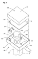
- FIG. 1 is a disassembled perspective view of a gas sensor 10 as a first embodiment of the present invention.
- This gas sensor 10 is a sensor for detecting a concentration of gasoline vapor utilizing the fact that a propagation speed of an ultrasonic wave changes according to a gas concentration.
- This gas sensor is arranged, for example, in a passage for purging gasoline from a canister, which is mounted on a vehicle using an internal combustion engine as a power source, to an inlet passage and used for the purpose of detecting a concentration of the gasoline to be purged, and the like.
- this gas sensor 10 includes: a flow path forming member 20 for forming a flow path through which gasoline vapor as an object of concentration detection passes; a detection element main body 40 which is housed in a housing section 22 integrally formed in this flow path forming member 20; a thermistor 60 for detecting a temperature of a gas passing through the flow path; an electronic circuit substrate 70 arranged above the detection element main body 40; and a metal case 80 to be fit in the housing section 22.
- the flow path forming member 20 is formed of synthetic resin containing a glass filler. Elasticity of the flow path forming member 20 is adjusted to a value suitable as a gas sensor.
- the detection element main body 40 is fixed to a recessed portion for attachment 24 provided in the housing section 22 by ultrasonic welding, and the thermistor 60 is inserted in and fixed to an insertion hole for attachment 25.
- the detection element main body 40 and the thermistor 60 have a terminal for exchanging electric signals. This terminal is inserted in a corresponding attachment hole of the electronic circuit substrate 70 and fixed by soldering.
- the gas sensor 10 is manufactured by, after fixing the detection element main body 40 and the thermistor 60 to the housing section 22, attaching the electronic circuit substrate 70 to the housing section 22, further fitting the case 80 in the housing section 22, and then molding them with resin, for example, urethane resin.
- this flow path forming member 20 is provided with the housing section 22 for housing the detection element main body 40 above it and has a flow path through which a gas for detection of a concentration flows below the housing section 22.
- This flow path includes an introducing path 27 for introducing a gas containing gasoline vapor (hereinafter referred to as gas GS) into the gas sensor 10, a measurement chamber 28 for detecting a concentration of the gasoline vapor in this gas GS with an ultrasonic wave, and a bypass flow path 29 for bypassing the gas GS to the measurement chamber 28.
- the measurement chamber 28 and the bypass flow path 29 are provided substantially directly below the detection element main body 40 and substantially directly below the thermistor 60, respectively.
- a vertical section of the gas sensor 10 is shown in Fig. 2.
- Fig. 2 is a sectional view of the gas sensor 10 cut along a plane including axial lines of the introducing path 27 and the detection element main body 40.
- a flow path of the gas GS formed inside the flow path forming member 20 is divided into the introducing path 27, the measurement chamber 28, and the bypass flow path 29.
- the introducing path 27 extended in a substantially horizontal direction communicates with the bypass flow path 29 at a right angle and also communicates with the measurement chamber 28 via an introducing hole 32.
- the above-described measurement chamber 28 is equivalent to a "predetermine flow path of a gas" in claims. It is needless to mention that it is possible to realize the "predetermined flow path of a gas" in claims with a form other than this measurement chamber 28.
- an outlet 34 is formed in a lower part of the bypass flow path 29.
- the outlet 34 is connected to the inlet passage of the internal combustion engine by a not-shown hose.
- the gas GS introduced from the introducing path 27 is discharged to the inlet passage from the above-described outlet 34.
- an insertion hole 25 is formed at an end on the opposite side of the outlet 34 of the bypass flow path 29, and the thermistor 60 is attached to this insertion hole 25.
- the thermistor 60 detects a temperature of the gas GS flowing into the bypass flow path 29 from the introducing path 27 via the insertion with the insertion hole 25.
- an upper part of the measurement chamber 28 communicates with the recessed portion 24 via a communication hole 24a formed on a bottom surface of the recessed portion 24, and the detection element main body 40 is attached to this recessed portion 24.
- the detection element main body 40 detects a concentration of the gasoline vapor in the gas GS, which has flown into the measurement chamber 28, via the communication hole 24a. In this case, the concentration of the gasoline vapor is detected with a predetermined relationship with the detected temperature of the gas GS.
- a reflecting section 33 for reflecting an ultrasonic wave transmitted from the detection element main body 40 is formed below the measurement chamber 28. A function of this reflecting section 33 will be described later.
- the reflecting section 33 is formed by raising a central area of the bottom of the measurement chamber 28 by a predetermined distance (several millimetres in this embodiment). Consequently, a predetermined gap is formed around the reflecting section 33.
- the gap around this reflecting section 33 is directly connected to the bypass flow path 29 via a discharge flow path 35 communicating with the bottom of the measurement chamber 28. Consequently, the gas GS flowing in from the introducing path 27 through the introducing hole 32 fills inside the measurement chamber 28 and exits to the bypass flow path 29 from the discharge flow path 35 at a predetermined ratio.
- the discharge flow path 35 is provided in the bottom of the measurement chamber 28, in the case in which water vapor, gasoline vapor, or the like in the measurement chamber 28 condensed and liquefied, the discharge flow path 35 also functions as a drain for discharging water drips or oil drips.
- the recessed portion for attachment 24 provided with the communication hole 24a communicating with the measurement chamber 28, the insertion hole 25 for attaching a thermistor, and the like are formed.
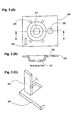
- a metal plate 36 shown in Fig. 3 is insert-molded in a place equivalent to this housing section 22. As shown in the figure, this metal plate 36 has a shape substantially following a bottom surface shape of the housing section 22 and has a recessed portion 37 corresponding to the recessed portion 24, an opening portion 38 corresponding to the insertion hole 25.
- This metal plate 36 includes a cut-raised portion 83 at its one comer. As shown in Fig.
- this cut-raised portion 83 is brought into a state in which it is vertically provided on the inner side of the housing section 22 and, when the electronic circuit substrate 70 is attached, inserted in an attachment hole 72 on the substrate.
- a land connected to a ground line is prepared in the attachment hole 72, and the cut-raised portion 83 is soldered to this land.
- a projected portion for terminal 22a is provided which is also used as a support base for mounting the electronic circuit substrate 70.
- a connector 31 for exchanging an electric signal is formed, and terminals forming the connector 31 penetrate through an external wall of the housing section 22 in this part.
- Three terminals are prepared for the connector 31 on its entrance side, and two terminals on both sides of the three terminals serve as power supply lines (grand and DC voltage Vcc) for supplying a power to this gas censor 10 from the outside and one in the center thereof serves as a signal output line from the gas center 10.
- the number of the terminals of this connector 31 is four (31a to 31d) as shown in Fig.
- the terminal 31c for the ground line has a shape branched into two in the middle.
- One of the two branched terminals 31d is extended upward and inserted in an insertion hole 85 prepared in a corresponding position of this case 80 when the case 80 is assembled. After the insertion, the terminal 31d is soldered or brazed to the case 80. As a result, the entire case 80 is electrically coupled to the ground line.
- a not-shown support base is formed for the purpose of mounting the electronic circuit substrate 70.
- the detection element main body 40 includes an element case 42 made of synthetic resin.
- An opening portion is provided on a bottom surface of this element case 42, and a circular protective film 48 using a material having an anti-gasoline property is adhered to an end face 45 around this opening portion so as to cover the opening portion.
- a step portion 46 is formed in an outside edge of the end face 45.
- the above-mentioned element case 42 to which the protective film 48 is adhered is equivalent to a "housing" in claims. It is needless to mention that it is also possible to realize the "housing" in claims according to a form other than this element case 42 to which the protective film 48 is adhered.
- the element case 42 includes a flange section 41 of a shape extended to the outside above it and a housing section 43 below the flange section 41.
- the flange section 41 is formed in diameter larger than the recessed portion 24 provided in the housing section 22, and the housing section 43 is formed in a diameter smaller than the recessed portion 24.
- a projection for welding 59 is formed in a circular shape substantially in the center of a lower surface of the flange section 41.
- the element case 42 has a sectional shape of a substantially reverse "L".
- An internal peripheral surface of the element case 42 is tapered at approximately 11 degrees with respect to a vertical surface. Therefore, a part equivalent to the external wall of the housing section 43 becomes thicker as it is closer to the lower part, that is, the protective film 48.
- the housing section 43 of the element case 42 has the external wall which is thin and excellent in flexibility in the vicinity of its joint with the flange section 41, and on the end face 45 on the lower side, has an area sufficient for sticking the protective film 48.
- Projecting portions 56a and 56b of a shape projecting to an inner side of the case is provided in this element case 42, and terminals 55a and 55b are embedded in these projecting portions 56a and 56b. As shown in Fig. 5, one end of each of the terminals 55a and 55b is slighted projected to the inner side of the case, and the other end of each of the terminals 55a and 55b is projected to above the case.
- an acoustic matching plate 50 of a substantially columnar shape, a piezoelectric element 51, and a tube body 52 are housed in the element case 42.
- the above-mentioned acoustic matching plate 50 is equivalent to a "matching member" in claims.
- the acoustic matching plate 50 is adhered and fixed to substantially a center of the protective film 48, and a piezoelectric element 51 is adhered and fixed to substantially a center of an upper surface of this acoustic matching plate 50.
- the acoustic matching plate 50 is provided for transmitting vibration of the piezoelectric element 51 into the air (to the measurement chamber 28 in this embodiment) efficiently via the protective film 48.
- Vibration of the piezoelectric element 51 can be transmitted into the measurement chamber 28 as an ultrasonic wave efficiently by jointing the piezoelectric element 51 to the protective film 48 via the acoustic matching plate 50 rather than adhering it directly thereto.
- an ultrasonic wave has a characteristic that it easily reflects in a place where there is a difference of densities of media. Note that, although a plate formed by hardening a large number of small glass balls with epoxy resin was used as the acoustic matching plate 50 in this embodiment, it is needless to mention that it is possible to use a material other than this.
- the piezoelectric element 51 is an electrostrictive element such as piezoelectric formed in a columnar shape and is cut out with directions of gratings arranged such that distortion occurs only in an axial direction when a voltage is applied to electrodes formed on its upper and lower surfaces in the axial direction.
- a piezoelectric element 51 a crystal such as piezoelectric ceramics or a rock crystal can be used appropriately.
- the electrodes may be formed with a technique such as vapor deposition on the upper and lower surfaces of the piezoelectric element 51 or may be formed by sticking a metal thin plate to it.
- One ends of two lead wires 54a and 54b are soldered to the electrodes of the piezoelectric element 51. As shown in Fig. 5, the other ends of the two lead wires 54a and 54b are soldered to one ends of the respective terminals 55a and 55b projecting from the projecting portion 56a and 56b of the element case 42.
- the piezoelectric element 51 functions as a transmitter for transmitting an ultrasonic wave into the measurement chamber 28 and, at the same time, in this embodiment, also functions as a receiver for receiving ultrasonic vibration and outputting an electric signal. It is needless to mention that it is also possible to provide an element for transmission and an element for reception separately to make a gas sensor.
- a tube body 52 of a cylindrical shape is mounted on the protective film 48 in a position where it surrounds the acoustic matching plate 50 and the piezoelectric element 51.
- This tube body 52 is formed by rolling a polyethylene terephthalate film 52a and a copper foil 52c, which are stuck together via an adhesion layer 52b, in a tubular shape with the copper foil 52c side being inside to fit and stick end faces on both sides together. Details of this tube body 52 will be described later.
- the lead wires 54a and 54b of the piezoelectric element 51 are connected to the terminals 55a and 55b.
- resin is filled in the element case 42 as a filler, whereby a filled layer 99 is formed in the element case 42 as shown in Fig. 5.
- the acoustic matching plate 50, the piezoelectric element 51, the tube body 52, the lead wires 54a and 54b are brought into a state in which they are embedded in the filled layer 99. Consequently, assembly of the detection element main body 40 is completed.
- urethane is used as the filler in this embodiment.
- the above-described tube body 52 is equivalent to an "intervening member” in claims. It is needless to mention that it is possible to realize the "intervening member” in claims according to a form other than this tube body 52.
- the above-described filled layer 99 is equivalent to a "filled layer” in claims. It is needless to mention that it is possible to realize the "filled layer” in claims according to a form other than this filled layer 99.
- the detection element main body 40 is formed in the disk shape as shown in Fig. 1.
- the flange section 41 of the detection element main body 40 is adhered to the recessed portion 24 of the housing section 22 firmly by ultrasonic welding the projection 59 formed on a lower surface of the flange section 41.
- A-4 Structure of the electronic circuit substrate 70 and a technique for detecting a vapor concentration of gasoline
- the electronic circuit substrate 70 is a glass epoxy substrate on which a circuit pattern is formed in advance by etching or the like, and through-holes or the like are provided in positions for attaching various components (e.g., various components for signal processing such as an integrated circuit (IC) for signal processing, a resistor, and a capacitor).
- various components e.g., various components for signal processing such as an integrated circuit (IC) for signal processing, a resistor, and a capacitor.
- IC integrated circuit
- a capacitor e.g., various components for signal processing such as an integrated circuit (IC) for signal processing, a resistor, and a capacitor.
- the electronic circuit substrate 70 to which the above-described various components are attached is mounted on the housing section 22 of the flow path forming member 20. Thereafter, an electric circuit configuration of the electronic circuit substrate 70 is completed by soldering the terminals inserted in the respective attachment holes of the electronic circuit substrate 70 to lands around them.
- this electronic circuit substrate 70 includes a microprocessor 91 as a main component and also includes respective circuit elements connected to the microprocessor 91, that is, a digital/analog converter (D/A converter) 92, a driver 93, a comparator 97 to which an amplifier 96 is connected, and the like.
- the driver 93 and the amplifier 96 are connected to the detection element main body 40.
- the thermistor 60 is directly connected to an analog input port of the microprocessor 91.
- the driver 93 is a circuit for receiving an instruction from the microprocessor 91 to drive the piezoelectric element 51 of the detection element main body 40 for a predetermined time. Upon receiving an instruction from the microprocessor 91, the driver 93 outputs plural rectangular waves. Upon receiving signals of the rectangular waves outputted by the driver 93, the piezoelectric element 51 vibrates and functions as a transmitter to transmit an ultrasonic wave into the measurement chamber 28. Such an ultrasonic wave which is transmitted from the piezoelectric element 51 into the measurement chamber 28 as the piezoelectric element 51 vibrates upon receiving an output signal from the driver 93 is hereinafter referred to as an ultrasonic wave for detection DW.
- this signal of a rectangular wave outputted by the driver 93 is equivalent to a "predetermined signal" in claims. It is needless to mention that it is also possible to realize the "predetermined signal” in claims according to a form other than this signal of a rectangular wave outputted by the driver 93.
- the ultrasonic wave transmitted into the measurement chamber 28 travels straight ahead while keeping relatively high directivity and reflects on the reflecting section 33 of the bottom portion of the measurement chamber 28 to return.
- vibration of the ultrasonic wave is transmitted to the piezoelectric element 51 via the protective film 48 and the acoustic matching plate 50.
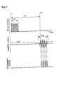
- the piezoelectric element 51 having received the vibration of the ultrasonic wave then functions as a receiver to output an electric signal according to the vibration to the amplifier 96. This state is shown in Fig. 7. In Fig.
- a transmission period P1 represents a period during which the piezoelectric element 51 receives the signal from the driver 93 and transmits the ultrasonic wave for detection DW (period during which the piezoelectric element 51 functions as a transmitter), and an input period P2 represents a period during which a signal of the piezoelectric element 51 having received the vibration of the ultrasonic wave is inputted in the amplifier 96 (period during which the piezoelectric element 51 functions as a receiver).
- the signal of the piezoelectric element 51 at the time when it functions as the receiver is inputted in the amplifier 96 and amplified.
- An output of this amplifier 96 is inputted in the comparator 97 and compared here with a threshold value Vref prepared in advance.
- the threshold value Vref is in a level in which an error signal outputted by the amplifier 96 due to an influence of a noise can be distinguished.
- the piezoelectric element 51 is adhered to the acoustic matching plate 50 and filled with a filler, since it is capable of performing free end vibration to some extent, it may perform damped vibration over a predetermined period even after a drive signal outputted from the driver 93 is lost.
- Such an ultrasonic wave transmitted from the piezoelectric element 51 as the piezoelectric element 51 vibrates upon receiving an influence of a reverberation in the element case 42 is hereinafter referred to as a noise ultrasonic wave NW.
- the comparator 97 compares the signal from the amplifier 96 with the threshold value Vref, thereby reversing its output when a magnitude of vibration received by the piezoelectric element 51 becomes equal to or larger than a predetermined magnitude.
- This expression (1) is a general expression which is established for a gas in which plural components are mixed, and a variable n is a suffix indicating that the expression concerns an nth component. Therefore, C pn represents a constant pressure specific heat of the nth component of the gas GS existing in the measurement chamber 28, C vn represents an isovolumetric specific heat of the nth component of the gas GS in the measurement chamber 28, M n represents a molecular weight of the nth component, and X n represents a mixture ratio of the nth component. In addition, R represents a gas constant and T represents a temperature of the gas GS in the measurement chamber 28.
- the propagation speed C is defined by the temperature T and the concentration ratio X n of the gas GS in the measurement chamber 28.
- the microprocessor 91 performs an arithmetic operation in accordance with the above expression at a high speed and outputs a signal corresponding to the found vapor concentration of gasoline via the D/A converter 92.
- This signal is outputted to the outside via the terminal 31b of the connector 31.
- this signal is outputted to a computer, which controls a fuel injection amount of an internal combustion engine, and is used here for processing such as correcting the fuel injection amount taking into account a purge amount of gasoline from a canister.
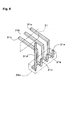
- Fig. 8 is a disassembled perspective view showing a relationship between the tube body 52 and the acoustic matching plate 50 and piezoelectric element 51. As shown in Figs. 5 and 8, the tube body 52 is provided in an area between the acoustic matching plate 50 and piezoelectric element 51 and the element case 42 so as to surround the acoustic matching plate 50 and the piezoelectric element 51.
- the tube body 52 is formed in a three-layer structure consisting of three types of media with different densities, namely, the polyethylene terephthalate (PET) film 52a, the adhesion layer 52b, and the copper foil 52c. Consequently, an acoustic impedance of the tube body 52 has different values in the respective layers.
- PET polyethylene terephthalate
- the tube body 52 is formed with the polyethylene terephthalate film 52a on its outer side (element case 42 side shown in Fig. 5) and the copper foil 52c having a larger density than the polyethylene terephthalate film 52a on its inner side (piezoelectric element 51 side shown in Fig. 5).
- the copper foil 52c which is a medium having a larger density than urethane resin serving as a filler is used on the inner side of the tube body 52.
- this tube body 52 since an inner diameter of this tube body 52 substantially coincides with an outer diameter of the acoustic matching plate 50, the tube body 52 is closely attached to the external periphery of the acoustic matching plate 50 in a state in which it is mounted on the protective film 48. As a result, the tube body 52 is arranged in a position closer to the acoustic matching plate 50 and piezoelectric element 51 than the element case 42 in an area between the acoustic matching plate 50 and piezoelectric element 51 and the element case 42 in a state in which it is close to the acoustic matching plate 50 and piezoelectric element 51. Note that the tube body 52 and the acoustic matching plate 50 are not adhered to each other. In addition, the copper foil 52c on the inner side of the tube body 52 is not adhered to the filled layer 99.
- the external diameter of the piezoelectric element 51 is made smaller than the external diameter of the acoustic matching plate 50. Therefore, a gap is formed between the internal surface of the tube body 52 surrounding the acoustic matching plate 50 and the piezoelectric element 51 and the side of the piezoelectric element 51.
- openings 53 are provided in the tube body 52. These openings 53 are provided in positions offset upward along the axial direction of the piezoelectric element 51 (in other words, in a position offset to the opposite side of the measurement chamber 28). Therefore, after assembly, the openings 53 of the tube body 52 exist in positions corresponding to the external periphery of the piezoelectric element 51 rather than the external periphery of the acoustic matching plate 50. Note that, in Fig. 8, for convenience of understanding, respective layers 52a, 52b, and 52c forming the tube body 52 are drawn integrally.
- the acoustic matching plate 50 and the piezoelectric element 51 are adhered and fixed in the element case 42 to which the protective film 48 is adhered in an opening portion of its bottom surface, and the tube body 52 is provided so as to surround the acoustic matching plate 50 and the piezoelectric element 51.
- the noise ultrasonic wave NW is emitted in a direction other than a regular direction (measurement chamber 28 side) from the piezoelectric element 51 and the acoustic matching plate 50.
- a noise ultrasonic wave NWs emitted in an internal peripheral surface direction of the element case 42 is divided into a component NWs1 to be reflected on an interface with the copper foil 52c of the tube body 52 and a component NWs2 transmitting through the copper foil 52c.
- the component NWs2 which has transmitted through the copper foil 52c is further divided into a component NWs3 to be reflected on an interface with the adhesion layer 52b and a component NWs4 transmitting through the adhesion layer 52b.
- the noise ultrasonic wave NWs collides with the tube body 52 to be dispersed in terms of time and energy, the energy of the noise ultrasonic wave NWs returning to the piezoelectric element 51 is attenuated.
- an acoustic level of the noise ultrasonic wave NWs becomes low compared with the case without the tube body 52. Note that it has become clear according to results of experiments to be described later that a duration of a reverberation is reduced in the case in which the tube body 52 is provided.
- Fig. 9 is a graph showing temporal transition of a vibration state of the piezoelectric element 51 after the piezoelectric element 51 has transmitted the ultrasonic wave for detection DW upon receiving an output signal from the driver 93 (after elapse of the transmission period P1 in Fig. 7).
- the horizontal axis shows an elapsed time and the vertical axis shows an amplitude of the piezoelectric element 51.
- This amplitude of the piezoelectric element 51 shows an amplitude detected in a vibration detector connected to the piezoelectric element 51.
- a value of "Vref' of the amplitude of the piezoelectric element 51 indicates an amplitude to be detected in the case in which the piezoelectric element 51 is in a vibration state equivalent to a threshold value Vref.
- an input period P2 indicates a period during which the piezoelectric element 51 functions as a receiver.
- the amplitude of the piezoelectric element 51 promptly attenuates after it is generated as the piezoelectric element 51 is vibrated by the driver 93. That is, the amplitude of the piezoelectric element 51 becomes smaller than "Vref" after the transmission of the ultrasonic wave for detection DW and becomes feeble before a beginning of the input period P2. This means that a reverberation in the element case 42 is promptly reduced after the transmission of the ultrasonic wave for detection DW.
- the noise ultrasonic wave NW transmitted from the piezoelectric element 51 is brought into a state in which it is extremely feeble, and the piezoelectric element 51 receives the ultrasonic wave for detection DW reflected by the reflecting section 33 in this state. If the noise ultrasonic wave NW is feeble in this way, even in the case in which it interferes with the ultrasonic wave for detection DW as a reflected wave, since a degree of interference is weak, a waveform or a phase of the ultrasonic wave for detection DW is never disturbed significantly. Therefore, it becomes possible to accurately obtain an elapsed time since a first ultrasonic wave for detection DW is transmitted until it returns to the piezoelectric element 51. In addition, a signal of a level equal to or higher than the threshold value Vref can be inputted in the comparator 97 surely as the piezoelectric element 51 receives the ultrasonic wave DW which has returned.
- the gas sensor 10 of the first embodiment it becomes possible to promptly reduce an acoustic level of the noise ultrasonic wave NW transmitted from the piezoelectric element 51, and accurate detection of a concentration of gasoline vapor based upon the ultrasonic wave for detection DW can be secured.
- the copper foil 52c on the inner side of the tube body 52 is brought into a state in which it is not adhered to the filled layer 99 in the element case 42. In this way, the surface of the copper foil 52c slides against the filled layer 99, whereby a thermal stress applied to the periphery of the acoustic matching plate 50 and the piezoelectric element 51 is eased.
- a loss of an ultrasonic wave energy of a reverberation is generated on that interface. Therefore, a duration of the reverberation can be further reduced.
- the tube body 52 after arranging the tube body 52 on the protective film 48 in the bottom of the element case 42 to be close to the acoustic matching plate 50 and the piezoelectric element 51, a filler is filled in the element case 42 to form the filled layer 99.
- a large number of openings 53 are provided in this tube body 52, the filler penetrates into the openings 53 at the time when the filler is filled. Therefore, when the filler is hardened, the tube body 52 and the inner side portion thereof are bonded with the outer side portion of the tube body 52.
- the openings 53 provided in the tube body 52 are formed in a position offset upward along an axial direction of the piezoelectric element 51. Consequently, positional movement of the acoustic matching plate 50 and the piezoelectric element 51 following the thermal expansion of the filled layer 99 is suppressed and, at the same time, appropriate slip of the surface of the copper foil 52c against the filled layer 99 is secured, and a thermal stress applied to the periphery of the acoustic matching plate 50 and the piezoelectric element 51 is eased. Therefore, reduction of a duration of a reverberation can be realized while securing accuracy of detection for a concentration of gasoline vapor.
- the tube body 52 is formed using three types of media in the first embodiment, the tube body may be formed only with one type of material.
- a material in this case a material with a quality different from urethane resin serving as the filled layer (e.g., metal such as copper) is possible.
- the noise ultrasonic wave NWs emitted in the internal peripheral surface direction of the element case 42 transmits through the tube body or collides with the tube body to reflect, whereby its energy is attenuated. Therefore, the duration of the reverberation in the filled layer 99 can be reduced compared with the case without the tube body.
- the tube body 52 is formed in a shape surrounding the entire periphery of the acoustic matching plate 50 and the piezoelectric element 51 in the first embodiment, it is also possible to adopt a structure in which the tube body 52 is constituted from plural members and the respective members are arranged around the acoustic matching plate 50 and the piezoelectric element 51.
- the members constituting the tube body 52 may be arranged with gaps among the members. In this way, a state in which the filler has flown in the gaps provided among the members is obtained, and in the case in which the filled layer 99 expands, movements of the respective members constituting the tube body 52 are restricted by the expanded filler. Therefore, as in the case in which the opening 53 is provided in the above-mentioned embodiment, the acoustic matching plate 50 and the piezoelectric element 51 can be prevented from moving in a direction toward the measurement chamber 28.
- the filled layer 99 in the element case 42 only has to be formed with a height at which the piezoelectric element 51 is embedded.
- the filled layer 99 is provided with a height at which the top end of the tube body 52 is not embedded and the lead wires 54a and 54b of the piezoelectric element 51 are connected to the terminals 55a and 55b via the copper foil 52c at the top end of the tube body 52.
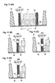
- one element case in which the tube body 52 was not provided around the acoustic matching plate 50 and the piezoelectric element 51 was prepared and, at the same time, four types of element cases in which one of tube bodies 52A to 52C was provided around the acoustic matching plate 50 and the piezoelectric element 51 were prepared as shown in Fig. 11.
- the tube body 52A without the opening 53, the tube body 52B in which the opening 53 was formed in its upper part, the tube body 52D in which the opening 53 was formed in its lower part, and the tube body 52C in which the opening 53 was formed between the upper part and the lower part (hereinafter referred to as central part) are housed.
- the tube body 52E was a tube body in which directions of the polyethylene terephthalate film 52a and the copper foil 52c were opposite to the direction of the tube body 52B (i.e., the polyethylene terephthalate film 52a was on the inner side (piezoelectric element 51 side shown in Fig. 5) and the copper foil 52c was on the outer side (element case 42 side shown in Fig.
- a material and an inner diameter D of the tube body 52E were assumed to be the same as those of the tube body 52B.
- a result of this experiment 2 is shown in Fig. 12(B).
- a result was obtained in that a duration of a reverberation in the element case including the tube body 52E was shorter than that in the element case which was not provided with the tube body 52 and was longer than that in the element case including the tube body 52B.
- the tube bodies 52F and 52G were tube bodies in which inner diameters D thereof were made larger than that of the tube body 52B, the inner diameter D of the tube body 52F was " ⁇ 12.7" and the inner diameter D of the tube body 52G was " ⁇ 14.5".
- the material of the tube body 52B was changed to a tube body 52H or 521 described below, and a duration of a reverberation was measured with the same method as the above-described experiment 1.
- the tube body 52H was formed in a three-layer structure consisting of the polyethylene terephthalate film 52a, the adhesion layer 52B, and aluminum, and the tube body 52I was a tube body in which the copper foil 52c was adhered between two polyethylene terephthalate films.
- Fig. 12(D) A result of this experiment 4 is shown in Fig. 12(D).
- Fig. 12(D) a result was obtained in that the duration of the reverberation in each element case including the tube body 52H or 521 was shorter than that of the element case which was not provided with the tube body 52 and longer than that of the element case including the tube body 52B, and the time during which the reverberation continued was shorter in the order of the element case including the tube body 52H and the element case including the tube body 521.
- a gas sensor of the second embodiment is different from the gas sensor of the first embodiment in that a plate-like body 165Q, which is formed using a porous body, is provided in the element case 42 of the detection element main body 40.
- a sectional structure of a detection element main body 140 provided with the plate-like body 165Q in an element case 142 in this way is shown in Fig. 13.
- Fig. 13 represents a section corresponding to Fig. 5.
- numerals of second and first positions and alphabets following them of symbols are represented using the same numerals or alphabets as those in Fig. 5.
- a tube body 152 is the same as the above-mentioned tube body 52 and is arranged in the same position as the tube body 52.
- the plate-like body 165Q made of foamed silicon is provided on a surface (hereinafter referred to as upper surface) of a piezoelectric element 151 opposed to a surface of a filled layer 199.
- the above-mentioned plate-like body 165Q is equivalent to the "surface member" in claims.
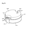
- FIG. 14 A perspective shape in the vicinity of the upper surface of the piezoelectric element 151 is shown in Fig. 14.
- a positive electrode 151a and a negative electrode 151b are formed by evaporation on the upper surface and the lower surface of the piezoelectric element 151, respectively.
- the negative electrode 151b has a folded-back portion 151c which is a portion for taking out input and output from the negative electrode 151b. This folded-back portion 151c is folded back to the upper surface of the piezoelectric element 151 so as not to come into contact with the positive electrode 151a.
- One ends of the lead wires 154a and 154b are soldered to the positive electrode 151 a and the folded-back portion 151c of the negative electrode 151b, respectively.
- the plate-like body 165Q is adhered to an area excluding the portion, where the lead wire 154a is soldered, on the positive electrode 151 a and fixed to the piezoelectric element 151.
- a silicon adhesive which is capable of adhering the plate-like body 165Q to the positive electrode 151a of the piezoelectric element 151 without a gap is used as an adhesive for the plate-like body 165Q. It is needless to mention that it is also possible to use an adhesive material (e.g., a couple-face tape) other than the silicon adhesive. In the case in which the couple-face tape is used, reduction of hardening time of an adhesive and reduction of working man-hour required for adhesion can be realized.
- an adhesive material e.g., a couple-face tape
- this reverberation decreased promptly according to actions of the tube body 152 and the plate-like body 165Q, and time during which the reverberation continues is further shorten. In this way, since the time during which the reverberation continues is further shortened, an acoustic level of a noise ultrasonic wave NW transmitted from the piezoelectric element 151 is reduced more promptly.
- an energy of a noise ultrasonic wave NWs emitted in the internal peripheral surface direction of the element case 142 (horizontal direction in Fig. 13) by vibration of the piezoelectric element 151 and the acoustic matching plate 150 is attenuated by the collision of the noise ultrasonic wave NWs with the tube body 52 as in the first embodiment.
- a noise ultrasonic wave NWu emitted in the surface direction of the filled layer 199 upward direction in Fig.
- the noise ultrasonic wave NWu collides with the hardened silicon adhesive or the plate-like body 165Q to be dispersed in terms of time and energy, an energy of the noise ultrasonic wave NWu returning to the piezoelectric element 151 is attenuated. As a result, an acoustic level of the noise ultrasonic wave NWu is reduced compared with the case without the plate-like body 165Q.
- the above-mentioned components NWu3 and NWu4 collide with a surface of the porous body and a surface of an inner wall forming foams inside the porous body, respectively. Therefore, a degree of the noise ultrasonic wave NWu colliding with the plate-like body 165Q increases, and an attenuation efficiency of the energy of the noise ultrasonic wave NW increases. Thus, a gas sensor with a short duration of a reverberation can be realized.
- the plate-like body 165Q is adhered and fixed to the upper surface of the piezoelectric element 151. Consequently, in the case in which a temperature around a part where the gas sensor is set (hereinafter referred to as ambient temperature) rises, even if a force following expansion of the filled layer 199 acts on the plate-like body 165Q such that the plate-like body 165Q separates from the upper surface of the piezoelectric element 151, since the plate-like body 165Q stays on the upper surface of the piezoelectric element 151 against such a force, a situation in which foams are generated between the piezoelectric element 151 and the plate-like body 165Q is less likely to occur.
- ambient temperature a temperature around a part where the gas sensor is set
- the filled layer 199 in the element case 142 only has to be formed with a height at which the piezoelectric element 151 is embedded.
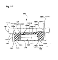
- a structure may be adopted in which a surface 165Qe on the opposite side of the piezoelectric element 151 of the plate-like body 165Q is not embedded in the filled layer 199, and a part of the plate-like body 165Q including the surface 165Qe is exposed above the surface of the filled layer 199.
- a gas sensor of the third embodiment is different from the gas sensor of the second embodiment in that the tube body 152 provided in the element case 142 is formed using a porous body.
- a section of such a detection element main body 240 is shown in Fig. 16.
- Fig. 16 shows a section corresponding to Fig. 13.
- numerals of second and first positions and alphabets following them of symbols are represented using the same numerals or alphabets as those in Fig. 13.
- a plate-like body 265Q is the same as the above-mentioned plate-like body 165Q and arranged in the same position as the plate-like body 165Q.
- a tube body 252Q made of foamed silicon is provided in an area between the acoustic matching plate 250 to the piezoelectric element 251 and the element case 242 so as to surround the acoustic matching plate 250 and the piezoelectric element 251.
- the above-mentioned tube body 252Q is equivalent to an "intervening member" in claims.
- the noise ultrasonic wave NWs collides with a surface of the porous body and a surface of an inner wall forming foams inside the porous body, a degree of the noise ultrasonic wave NWs colliding with the tube body 252Q increases. Therefore, time during which the reverberation continues can be shortened in the same degree as the second embodiment (the case in which a tube body is formed in the three-layer structure consisting of PET, an adhesive layer, and a copper foil).
- the filled layer 299 in the element case 242 only has to be formed with a height at which the piezoelectric element 251 is embedded, and it is allowable to change a state of embedding the plate-like body 265Q by the filled layer 299 to the same state as shown in Fig. 15.
- porous body to be used in formation of the plate-like body 165Q or 265Q or the tube body 252Q in the second and third embodiments foamed urethane, foamed rubber, porous ceramics, porous carbon, and the like are possible other than the foamed silicon.
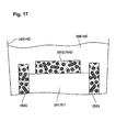
- the plate-like body 165Q or 265Q or the tube body 252Q is embedded in the filled layer 199 or 299.
- urethane as a filler penetrates into the porous body, an amount of air remaining in the porous body is reduced.
- the filler is filled in foams in this way, since a reflected component of the noise ultrasonic wave NW in the foam portion decreases, the noise ultrasonic wave NW reflected in the direction of the piezoelectric element 151 or 251 decreases, and the duration of the reverberation can be further suppressed.
- the piezoelectric element 151 or 251 becomes less susceptible to a local stress according to the increase in the volume of air in the porous body. Therefore, change in the sensitivity of the piezoelectric element 151 or 251 following the increase in the ambient temperature can be suppressed.
- a structure in which the urethane as a filler penetrates into foams existing inside the porous body, a state is obtained in which almost no air exists in the porous body embedded in the filled layer 199 or 299. Therefore, the characteristic change of the gas sensor following the increase in the ambient temperature can be suppressed totally.
- Such a structure can be realized by defoaming the porous body under vacuum after filling urethane, forming the plate-like body 165Q or 265Q or the tube body 252Q with a porous body having continuous foams, or the like.
- Fig. 18 shows explanatory views and table indicating conditions and results concerning the second and third embodiments.
- Fig. 18(A) represents four types of detection element main bodies which were used for the experiment. As shown in Fig. 18(A), in this experiment, the four types of detection element main bodies of the following (1) to (4) were prepared:
- Fig. 18(B) shows measurement values for the duration of the reverberation obtained for the respective gas sensors in a form of table. The below listed facts of ⁇ a> and ⁇ b> were found from the table shown in Fig. 18(B).
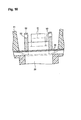
- Embodiments of the present invention have been described above. It is to be understood that the present invention is not limited to such embodiments at all, but can be applied to, for example, a temperature sensor or a specific heat sensor using an ultrasonic wave, and a sensor for detecting various characteristics of a gas with a method other than using the ultrasonic wave, which are within the scope of the invention as defined by the claims.
- envisaged modifications include a structure in which only a plate-like body serving as a porous body is provided without providing a tube body. According to this structure, the energy of the noise ultrasonic wave NWu emitted in a surface direction of a filled layer from a piezoelectric element is attenuated by collision with the plate-like body. Therefore, time during which a reverberation continues can be reduced more than in the past. In addition, it is allowable to form the above-mentioned plate-like body with a material other than copper (a material having a quality different from a filler).
- the gas sensor is constituted such that the piezoelectric element 51 is caused to function as a transmitter and a receiver of the ultrasonic wave for detection DW by providing the reflecting section 33 in the measurement chamber 28, the prompt reduction of a reverberation as shown in Fig. 9 has an important meaning even in the case in which the reflecting section 33 as described above is not provided and an piezoelectric element as a transmitter (hereinafter referred to as element for transmission) and an piezoelectric element as a receiver (hereinafter referred to as element for reception) are provided separately.
- a noise ultrasonic wave NW is prevented from being transmitted from the element for transmission after the transmission of the ultrasonic wave for detection DW.
- the strong noise ultrasonic wave NW is never transmitted to the element for reception. Therefore, a comparator 97 connected to the element for reception never outputs a signal from the element for reception having received the noise ultrasonic wave NW to the microprocessor 91 confusing it with a signal based upon the ultrasonic wave for detection DW.
Landscapes
- Physics & Mathematics (AREA)
- Acoustics & Sound (AREA)
- Health & Medical Sciences (AREA)
- Life Sciences & Earth Sciences (AREA)
- Chemical & Material Sciences (AREA)
- Analytical Chemistry (AREA)
- Biochemistry (AREA)
- General Health & Medical Sciences (AREA)
- General Physics & Mathematics (AREA)
- Immunology (AREA)
- Pathology (AREA)
- Investigating Or Analyzing Materials By The Use Of Ultrasonic Waves (AREA)
Abstract
Description
- The present invention relates to a gas sensor, and more specifically relates to a gas sensor which is provided facing a predetermined flow path of a gas and includes a detection element for receiving a predetermined signal to vibrate and detecting means which transmits a vibration wave generated by the vibration of the detection element in a flow path direction to detect characteristics of a gas.
- Conventionally, there is known a gas sensor which detects characteristics, for example, a concentration, a temperature, or a humidity, of a specific component of a gas existing in a flow path, using a detection element. In such a gas sensor, a signal from the detection element is electrically processed and outputted as an electric signal corresponding to the characteristics of the gas. As an example of the gas sensor, a gas concentration sensor which is provided in transportation equipment mounted with an internal combustion engine such as an automobile and detects a concentration of gasoline, gas oil, or the like utilizing a change in a propagation speed of a vibration wave of sound will be discussed.
- Such a gas sensor is arranged, for example, in a passage for purging gasoline from a canister mounted on the automobile to an inlet pipe of the internal combustion engine. The gas concentration sensor includes a flow path of a predetermined volume through which a gas containing gasoline vapor in the above-described passage flows and a detection element which is provided facing this flow path and detects a gas concentration. The gas concentration sensor vibrates the detection element in detecting the gas concentration and transmits a vibration wave (e.g., ultrasonic wave) generated by this vibration in a flow path direction. Such a vibration wave which is transmitted in the flow path direction of the gas from the detection element by the detection element vibrating for detection of the gas concentration is hereinafter referred to as a vibration wave for detection. A speed of the vibration wave passing through the flow path changes according to a concentration of gasoline vapor existing in the flow paths The gas concentration sensor detects a speed of the vibration wave for detection passing through a flow path of a fixed flow path length with a receiver for receiving the vibration wave for detection, finds the concentration of the gasoline vapor from a result of this detection, and outputs it.
- In such a conventional gas sensor, the detection element for transmitting the vibration wave for detection is arranged in a housing which is formed of resin or the like with high heat resistance (e.g., see JP-A-2000-206099). In addition, since it is necessary to keep a position of the detection element constant in order to accurately detect a speed of the vibration wave for detection passing through the gas flow path, a filled layer is formed by filling a filler such as urethane in the housing, in which the detection element is arranged, to seal the detection element and regulate a positional movement of the detection element.
- However, in such a gas sensor for detecting a gas concentration utilizing a vibration wave from a detection element, a reverberation may occur in a filled layer in which the detection element is embedded following vibration of the detection element, and as the detection element is affected by this reverberation, it is likely that characteristics of a gas such as a gas concentration cannot be detected accurately.
- That is, in the case in which a detection element is used as both a detection element for transmission and a detection element for reception, it is likely that, if a reverberation in the filled layer lasts long, a vibration wave emitted in the direction different from the transmission direction of the vibration wave for detection by vibration of the detection element affected by this reverberation (hereinafter referred to as noise vibration wave) interferes with the vibration wave for detection, and accurate detection of a gas concentration based upon the vibration wave for detection cannot be performed. In addition, in the case in which the detection element for transmission and the detection element for reception are provided separately, it is also likely that, if a reverberation in the filled layer lasts long, after a vibration wave for detection is transmitted to a gas flow path, a noise vibration wave is transmitted to the gas flow path from the detection element affected by the reverberation, and accuracy of detection of a gas concentration based upon the vibration wave for detection falls.
- A characteristic is observed that such a reverberation is continued over a longer period under a higher temperature. Therefore, under an environment in which temperature tends to increase such as in the vicinity of a passage for purging gasoline or a gas flow path in the gas sensor, a reverberation may increase to make accurate detection of a gas concentration difficult.
- In addition, in the conventional gas sensor, it is likely that, in the case in which temperature increases in the gas sensor, the filler in the housing thermally expands and a position of the detection element moves in the housing following this thermal expansion. In the case in which such positional movement occurs, since a flow path length of the gas flow path changes and time for the vibration wave for detection passing through the gas flow path changes following the change in the flow path length, it is likely that accuracy of detection of a gas concentration based upon the vibration wave for detection falls.
- Thus, the present invention adopts a structure as described below for the purpose of solving at least one of the above-described problems and providing a gas sensor which is capable of detecting a gas concentration accurately under high temperature.
- A gas sensor of the present invention is a gas sensor including a detection element which is provided facing a predetermined flow path of a gas and receives a predetermined signal to vibrate and detecting means which transmits a vibration wave, which is generated by the vibration of the detection element in the flow path direction, as a vibration wave for detection to detect characteristics of the gas, characterized by comprising:
- a housing for housing the detection element in a form capable of transmitting the vibration wave for detection in the flow path direction;
- an attenuation member which is provided in the housing and with which the vibration wave emitted in a direction different from the transmitting direction of the vibration wave for detection collides to have an energy thereof attenuated; and
- a filled layer which is formed by filling a predetermined filler in the housing at least up to a position where the detection element is embedded.
- According to the gas sensor of the above-described structure, the element for transmitting a vibration wave for detection in a flow path direction of a gas according to vibration and an attenuation member with which vibration wave (noise vibration wave) emitted in a direction different from a transmission direction of the vibration wave for detection collides to have an energy thereof attenuated are provided in the housing, and the filled layer is formed by filling the predetermined filler at least up to a position where the detection element is embedded in the housing. Consequently, in the case in which a reverberation occurs in the filled layer following the transmission of the vibration wave for detection due to vibration of a detection element having received a predetermined signal, a noise vibration wave emitted by the vibration of this detection element affected by the reverberation collides with the attenuation member to have an energy thereof attenuated. Consequently, the reverberation generated in the filled layer promptly decreases and a duration of the reverberation is reduced. Therefore, accurate detection of characteristics of the gas based upon the vibration wave for detection can be secured.
- The attenuation member is preferably set in a propagation route of noise vibration wave to be emitted in term of increasing certainty of collision with the noise vibration wave. As an example of a set position of the attenuation member, a position surrounding the detection element between the housing and the detection element, a surface of the detection element opposed to a surface of the filled layer, and the like are possible. The attenuation member set in the former position is hereinafter referred to as an intervening member and the attenuation member set in the latter position is hereinafter referred to as a surface member. In this case, a structure in which one of the intervening member and the surface member is set may be adopted or a structure in which both the intervening member and the surface member are set may be adopted. It is needless to mention that it is also possible to set the attenuation member in a position other than the above-mentioned position cited as an example.
- In the case in which the above-mentioned intervening member is provided as the attenuation member, since the energy of a noise vibration wave emitted in a direction of an internal peripheral surface of the housing is attenuated by collision with the intervening member, a reverberation generated in the filled layer can be reduced promptly. By adopting a structure in which this intervening member surrounds the entire periphery of the detection element, an attenuation efficiency of reverberation can be further increased.
- It was also found that, if the intervening member was formed using plural media with different densities, a reverberation was further reduced in duration. If such a structure is adopted, it is possible that a noise vibration wave generated in the filled layer tends to be reflected by the intervening member, and an attenuation efficiency of an energy of the noise vibration wave increases. Therefore, a reverberation can be reduced early after its generation.
- It is also desirable that the intervening member is constituted by using a medium having a larger density than the filler on the detection element side. In this way, an attenuation efficiency of a reverberation can be further increased. More specifically, for example, a structure is possible in which the medium used in the housing side is synthetic resin and the medium used on the detection element side is a metal.
- In the case in which a metal is used on the detection element side of the intervening member, it is preferable to make this metal not adhered to the filled layer. In this way, since a metal surface of the intervening member is allowed to slide against the filled layer, a thermal stress generated in the periphery of the detection element is eased. In addition, since an interface in which the metal and the filled layer are not adhered to each other exists, a loss of energy of the noise vibration wave occurs on the interface. Therefore, the duration of the reverberation can be further reduced. A structure in which the intervening member has a predetermined number of holes may be adopted.
- It is also preferable to form the intervening member with a porous body. As such a porous body, foamed silicon, foamed urethane, foamed rubber, porous ceramics, porous carbon, and the like are possible. By using such a porous body, an attenuation efficiency of an energy of a noise vibration wave increases, and a gas sensor with a short duration of a reverberation can be realized.
- The gas sensor may have a structure in which the intervening member is arranged in a position adjacent to the detection element. In the case in which this structure was adopted, it was found that the attenuation efficiency of the noise vibration wave further increased and a reverberation could be reduced more promptly.
- A structure may be added in which a film which is mounted on an opening portion of a housing and partitions the housing and a flow path is provided, a matching member which is mounted on the film and transmits vibration of a detection element to a flow path via the film and a detection element mounted on a surface on the opposite side of the mounting surface of the matching member on the film are housed in the housing, and an intervening member is provided in a position surrounding the detection element and the matching member between the matching member and detection element and the housing (hereinafter referred to as "structure with a film"). In this structure with a film, in the case in which the intervening member is arranged in a position adjacent to the detection element, the detection element becomes less likely to be affected by thermal expansion of the filled layer, and positional movement of the detection element following the thermal expansion of the filled layer (e.g., the detection element moves in a direction toward a flow path of a gas) can be prevented surely. Therefore, accuracy of detection for characteristics of the gas can be further improved.
- In addition, in the structure with a film, in the case in which the metal used on the detection element side of the intervening member is made not adhered to the filled layer, it is also preferable to form the plural holes provided in the intervening member to be offset to the opposite side of the flow path side of the intervening member. In this way, the positional movement of the detection element following the thermal expansion of the filled layer is suppressed by the holes provided in the intervening member and, at the same time, the holes are formed to offset to the opposite side of the flow path side, whereby appropriate slip of the metal surface of the intervening member against the filled layer is secured, and the thermal stress generated in the periphery of the detection element is eased. Therefore, the duration of the reverberation can be further reduced while securing accuracy of detection for characteristics of the gas.
- In the case in which the above-mentioned surface member (which is provided on the surface of the detection element opposed to the surface of the filled layer) is provided as the attenuation member, since the energy of the noise vibration wave emitted in the surface direction of the filled layer is attenuated by collision with the surface member, a reverberation generated in the filled layer can be reduced promptly. In addition, in the case in which both the intervening member and the surface member are provided, since the attenuation efficiency of the energy of the noise vibration wave becomes higher than that in the case in which one of them is provided, the reverberation can be reduced more promptly and a duration of the reverberation can be further reduced.
- It is also desirable to adhere and fix the surface member to the detection element. In this way, in the case in which the filled layer expands following increase in an ambient temperature, the surface member exfoliates from the surface of the detection element, whereby a gas layer (foams) is less likely to be generated between the detection element and the surface member. As a result, the duration of the reverberation and sensitivity of the detection element never change largely with the detection element subjected to a local stress by the generation of such foams. Therefore, characteristic change of the gas sensor following the increase in the ambient temperature can be suppressed.
- It is also preferable to form the surface member with a porous body. In this way, the attenuation efficiency of the energy of the noise vibration wave increases, and a gas sensor with a short duration of a reverberation can be realized.
- It is also desirable to adopt a structure in which at least a part of the porous body is embedded in the filled layer and filler penetrates into the inside of the porous body. In this way, the filler filled in the housing penetrates into foams inside the porous body, and an interface between the porous body and the filler increases in the porous body. Therefore, the attenuation efficiency of the energy of the noise vibration wave in the interface increases, and the reverberation time can be further reduced. In addition, the characteristic change of the gas sensor following the increase in the ambient temperature can be suppressed. For example, in the case in which the filled layer expands following the increase in the ambient temperature, the duration of the reverberation and the sensitivity of the detection element never change largely with the detection element subjected to a local stress due to increase in an air volume in the porous body.
- The gas sensor may have a structure in which a reflecting section for reflecting a vibration wave, which is transmitted from one detection element in the flow path direction, in the direction of the one detection element is provided, and the one detection element receives the vibration wave reflected by the reflecting section, thereby detecting characteristics of the gas. In other words, this is a structure in which one detection element which has transmitted the vibration wave for detection in the flow path direction receives the vibration wave for detection reflected by the reflecting section after the transmission, thereby detecting characteristics of the gas. In the case in which this structure is adopted, again, as a result of an energy of a noise vibration wave being attenuated by the above-described action of the attenuation member, a reverberation promptly attenuates and a duration of the reverberation is reduced. Therefore, wrong detection of characteristics of the gas can be prevented while making the structure for detecting characteristics of a gas simple. For example, it becomes possible to avoid a situation in which, after a vibration wave for detection is transmitted toward a flow path of a gas by vibrating one detection element, a noise vibration wave with a large energy is transmitted from this one detection element and this noise vibration wave interferes with the vibration wave for detection reflected by the reflecting section, and accuracy of the vibration wave for detection received by the one detection element can be secured.
- Embodiments of the invention will now be described, by way of example only, with reference to the accompanying drawings in which:-
- Fig. 1 is an exploded perspective view of a
gas sensor 10 as an embodiment of the present invention; - Fig. 2 is a vertical section of the
gas sensor 10; - Figs. 3(A-C) are explanatory views showing a shape of a
metal plate 36 inserted in ahousing section 22; - Fig. 4 is a perspective view showing shapes of
terminals 31a to 31d provided in aconnector 31; - Fig. 5 is a sectional view showing a structure of a detection element
main body 40; - Fig. 6 is an explanatory view showing an electric structure of an inside of the
gas sensor 10; - Fig. 7 is a time chart illustrating a principle of detection of a concentration of gasolinc vapor using an ultrasonic wave;
- Fig. 8 is an explanatory view showing structures of an
acoustic matching plate 50, apiezoelectric element 51, and atube body 52 in a perspective shape; - Fig. 9 is a time chart showing a state in which an acoustic level of a noise ultrasonic wave NW is reduced in the
gas sensor 10; - Fig. 10 is an explanatory view showing movement of the
acoustic matching plate 50 and thepiezoelectric element 51 to be prevented by thegas sensor 10 of this embodiment; - Figs. 11(A-D) are explanatory views showing conditions of
experiment 1 concerning a first embodiment; - Figs. 12(A-D) are tables showing results of
experiments 1 to 4 concerning the first embodiment; - Fig. 13 is an explanatory view showing a sectional structure of a detection element
main body 140 provided in a gas sensor of a second embodiment of the present invention; - Fig. 14 is an explanatory view showing a perspective shape in the vicinity of an upper surface of a
piezoelectric element 151; - Fig. 15 is a sectional view showing a modified example of the second embodiment;
- Fig. 16 is an explanatory view showing a sectional structure of a detection element
main body 240 provided in a gas sensor of a third embodiment of the present invention; - Fig. 17 is an explanatory view showing, in a section, a state in which urethane as a filler penetrates into foams existing inside a porous body; and
- Figs. 18(A-B) are explanatory views and a table indicating conditions and results of experiments concerning the second and third embodiments.
-
- 10... Gas sensor
- 20... Flow path forming member
- 22... Housing section
- 22a ...Projected portion for terminal
- 24... Recessed portion
- 25... Insertion hole
- 27... Introducing path
- 28... Measurement chamber
- 29··· Bypass flow path
- 31··· Connector
- 31a to 31d ···Terminals
- 32··· Introducing hole
- 33...Reflecting section
- 34...Outlet
- 35... Discharge flow path
- 36···Metal plate
- 37...Recessed portion
- 38...Opening portion
- 40, 140, 240... Detection element main bodies
- 41... Flange section
- 42, 142, 242 ...Element cases
- 43 ...Housing section
- 45 ...End face
- 46 ...Step portion
- 48 ...Protective Film
- 50, 150, 250... Acoustic matching plates
- 51, 151, 251...Piezoelectric elements
- 52, 52A to 52I ...Tube bodies
- 52a ...Polyethylene terephthalate film
- 52b ...Adhesion layer
- 52c ...Copper foil
- 53... Openings
- 54a, 54b, 154a, 154b... Lead wires
- 55a, 55b ...Terminals
- 56a, 56b ... Projecting portions
- 59...Projection
- 60... Thermistor
- 65... Plate-like body
- 70... Electronic circuit substrate
- 72... Attachment hole
- 80...Case
- 83... Cut-raised portion
- 85... Insertion hole
- 91... Microprocessor
- 93...Driver
- 96 ...Amplifier
- 97... Comparator
- 99, 199, 299...Filled layers
- 151a ...Positive electrode
- 151b ...Negative electrode
- 151c ...Folded-back portion
- 165Q, 265Q ...Plate-like bodies
- 165Qe...Surface
- 252Q ...Housing
- DW ···Ultrasonic wave for detection
- NW, NWs, NWu ...Noise ultrasonic waves
- Modes for carrying out the present invention will be hereinafter described based upon an embodiment. Fig. 1 is a disassembled perspective view of a
gas sensor 10 as a first embodiment of the present invention. Thisgas sensor 10 is a sensor for detecting a concentration of gasoline vapor utilizing the fact that a propagation speed of an ultrasonic wave changes according to a gas concentration. This gas sensor is arranged, for example, in a passage for purging gasoline from a canister, which is mounted on a vehicle using an internal combustion engine as a power source, to an inlet passage and used for the purpose of detecting a concentration of the gasoline to be purged, and the like. - As shown in Fig. 1, roughly speaking, this
gas sensor 10 includes: a flowpath forming member 20 for forming a flow path through which gasoline vapor as an object of concentration detection passes; a detection elementmain body 40 which is housed in ahousing section 22 integrally formed in this flowpath forming member 20; athermistor 60 for detecting a temperature of a gas passing through the flow path; anelectronic circuit substrate 70 arranged above the detection elementmain body 40; and ametal case 80 to be fit in thehousing section 22. - The flow
path forming member 20 is formed of synthetic resin containing a glass filler. Elasticity of the flowpath forming member 20 is adjusted to a value suitable as a gas sensor. In addition, the detection elementmain body 40 is fixed to a recessed portion forattachment 24 provided in thehousing section 22 by ultrasonic welding, and thethermistor 60 is inserted in and fixed to an insertion hole forattachment 25. - As discussed later, the detection element
main body 40 and thethermistor 60 have a terminal for exchanging electric signals. This terminal is inserted in a corresponding attachment hole of theelectronic circuit substrate 70 and fixed by soldering. - The
gas sensor 10 is manufactured by, after fixing the detection elementmain body 40 and thethermistor 60 to thehousing section 22, attaching theelectronic circuit substrate 70 to thehousing section 22, further fitting thecase 80 in thehousing section 22, and then molding them with resin, for example, urethane resin. - As shown in Fig. 1, this flow
path forming member 20 is provided with thehousing section 22 for housing the detection elementmain body 40 above it and has a flow path through which a gas for detection of a concentration flows below thehousing section 22. This flow path includes an introducingpath 27 for introducing a gas containing gasoline vapor (hereinafter referred to as gas GS) into thegas sensor 10, ameasurement chamber 28 for detecting a concentration of the gasoline vapor in this gas GS with an ultrasonic wave, and abypass flow path 29 for bypassing the gas GS to themeasurement chamber 28. Themeasurement chamber 28 and thebypass flow path 29 are provided substantially directly below the detection elementmain body 40 and substantially directly below thethermistor 60, respectively. - In order to describe such a flow path structure in detail, a vertical section of the
gas sensor 10 is shown in Fig. 2. Fig. 2 is a sectional view of thegas sensor 10 cut along a plane including axial lines of the introducingpath 27 and the detection elementmain body 40. As shown in Fig. 2, a flow path of the gas GS formed inside the flowpath forming member 20 is divided into the introducingpath 27, themeasurement chamber 28, and thebypass flow path 29. The introducingpath 27 extended in a substantially horizontal direction communicates with thebypass flow path 29 at a right angle and also communicates with themeasurement chamber 28 via an introducinghole 32. - In this embodiment, the above-described
measurement chamber 28 is equivalent to a "predetermine flow path of a gas" in claims. It is needless to mention that it is possible to realize the "predetermined flow path of a gas" in claims with a form other than thismeasurement chamber 28. - As shown in Fig. 2, an
outlet 34 is formed in a lower part of thebypass flow path 29. In this embodiment, theoutlet 34 is connected to the inlet passage of the internal combustion engine by a not-shown hose. The gas GS introduced from the introducingpath 27 is discharged to the inlet passage from the above-describedoutlet 34. - As shown in Figs. 1 and 2, an
insertion hole 25 is formed at an end on the opposite side of theoutlet 34 of thebypass flow path 29, and thethermistor 60 is attached to thisinsertion hole 25. Thethermistor 60 detects a temperature of the gas GS flowing into thebypass flow path 29 from the introducingpath 27 via the insertion with theinsertion hole 25. - As shown in Figs. 1 and 2, an upper part of the
measurement chamber 28 communicates with the recessedportion 24 via acommunication hole 24a formed on a bottom surface of the recessedportion 24, and the detection elementmain body 40 is attached to this recessedportion 24. The detection elementmain body 40 detects a concentration of the gasoline vapor in the gas GS, which has flown into themeasurement chamber 28, via thecommunication hole 24a. In this case, the concentration of the gasoline vapor is detected with a predetermined relationship with the detected temperature of the gas GS. - As shown in Fig. 2, a reflecting
section 33 for reflecting an ultrasonic wave transmitted from the detection elementmain body 40 is formed below themeasurement chamber 28. A function of this reflectingsection 33 will be described later. - The reflecting
section 33 is formed by raising a central area of the bottom of themeasurement chamber 28 by a predetermined distance (several millimetres in this embodiment). Consequently, a predetermined gap is formed around the reflectingsection 33. The gap around this reflectingsection 33 is directly connected to thebypass flow path 29 via adischarge flow path 35 communicating with the bottom of themeasurement chamber 28. Consequently, the gas GS flowing in from the introducingpath 27 through the introducinghole 32 fills inside themeasurement chamber 28 and exits to thebypass flow path 29 from thedischarge flow path 35 at a predetermined ratio. Note that, since thedischarge flow path 35 is provided in the bottom of themeasurement chamber 28, in the case in which water vapor, gasoline vapor, or the like in themeasurement chamber 28 condensed and liquefied, thedischarge flow path 35 also functions as a drain for discharging water drips or oil drips. - As described above, in the
housing section 22 of the flowpath forming member 20, the recessed portion forattachment 24 provided with thecommunication hole 24a communicating with themeasurement chamber 28, theinsertion hole 25 for attaching a thermistor, and the like are formed. Ametal plate 36 shown in Fig. 3 is insert-molded in a place equivalent to thishousing section 22. As shown in the figure, thismetal plate 36 has a shape substantially following a bottom surface shape of thehousing section 22 and has a recessedportion 37 corresponding to the recessedportion 24, an openingportion 38 corresponding to theinsertion hole 25. Thismetal plate 36 includes a cut-raisedportion 83 at its one comer. As shown in Fig. 1, after being insert-molded, this cut-raisedportion 83 is brought into a state in which it is vertically provided on the inner side of thehousing section 22 and, when theelectronic circuit substrate 70 is attached, inserted in anattachment hole 72 on the substrate. A land connected to a ground line is prepared in theattachment hole 72, and the cut-raisedportion 83 is soldered to this land. - In one part adjacent to the cut-raised
portion 83 among four inside comers of thehousing section 22, a projected portion forterminal 22a is provided which is also used as a support base for mounting theelectronic circuit substrate 70. On the outside thereof, aconnector 31 for exchanging an electric signal is formed, and terminals forming theconnector 31 penetrate through an external wall of thehousing section 22 in this part. Three terminals are prepared for theconnector 31 on its entrance side, and two terminals on both sides of the three terminals serve as power supply lines (grand and DC voltage Vcc) for supplying a power to thisgas censor 10 from the outside and one in the center thereof serves as a signal output line from thegas center 10. The number of the terminals of thisconnector 31 is four (31a to 31d) as shown in Fig. 4 on thehousing section 22 side. This is because, as shown in the figure, the terminal 31c for the ground line has a shape branched into two in the middle. One of the twobranched terminals 31d is extended upward and inserted in aninsertion hole 85 prepared in a corresponding position of thiscase 80 when thecase 80 is assembled. After the insertion, theterminal 31d is soldered or brazed to thecase 80. As a result, theentire case 80 is electrically coupled to the ground line. In the remaining two parts among the comers of thehousing section 22, a not-shown support base is formed for the purpose of mounting theelectronic circuit substrate 70. - A structure of the detection element
main body 40 is shown in a sectional view of Fig. 5. As shown in Fig. 5, the detection elementmain body 40 includes anelement case 42 made of synthetic resin. An opening portion is provided on a bottom surface of thiselement case 42, and a circularprotective film 48 using a material having an anti-gasoline property is adhered to anend face 45 around this opening portion so as to cover the opening portion. Note that astep portion 46 is formed in an outside edge of theend face 45. - In this embodiment, the above-mentioned
element case 42 to which theprotective film 48 is adhered is equivalent to a "housing" in claims. It is needless to mention that it is also possible to realize the "housing" in claims according to a form other than thiselement case 42 to which theprotective film 48 is adhered. - The
element case 42 includes aflange section 41 of a shape extended to the outside above it and ahousing section 43 below theflange section 41. Theflange section 41 is formed in diameter larger than the recessedportion 24 provided in thehousing section 22, and thehousing section 43 is formed in a diameter smaller than the recessedportion 24. A projection for welding 59 is formed in a circular shape substantially in the center of a lower surface of theflange section 41. - As shown in Fig. 5, the
element case 42 has a sectional shape of a substantially reverse "L". An internal peripheral surface of theelement case 42 is tapered at approximately 11 degrees with respect to a vertical surface. Therefore, a part equivalent to the external wall of thehousing section 43 becomes thicker as it is closer to the lower part, that is, theprotective film 48. As a result, thehousing section 43 of theelement case 42 has the external wall which is thin and excellent in flexibility in the vicinity of its joint with theflange section 41, and on theend face 45 on the lower side, has an area sufficient for sticking theprotective film 48. - Projecting
portions element case 42, andterminals portions terminals terminals - As shown in Fig. 5, an
acoustic matching plate 50 of a substantially columnar shape, apiezoelectric element 51, and atube body 52 are housed in theelement case 42. In this embodiment, the above-mentionedacoustic matching plate 50 is equivalent to a "matching member" in claims. Theacoustic matching plate 50 is adhered and fixed to substantially a center of theprotective film 48, and apiezoelectric element 51 is adhered and fixed to substantially a center of an upper surface of thisacoustic matching plate 50. Theacoustic matching plate 50 is provided for transmitting vibration of thepiezoelectric element 51 into the air (to themeasurement chamber 28 in this embodiment) efficiently via theprotective film 48. Vibration of thepiezoelectric element 51 can be transmitted into themeasurement chamber 28 as an ultrasonic wave efficiently by jointing thepiezoelectric element 51 to theprotective film 48 via theacoustic matching plate 50 rather than adhering it directly thereto. This is because an ultrasonic wave has a characteristic that it easily reflects in a place where there is a difference of densities of media. Note that, although a plate formed by hardening a large number of small glass balls with epoxy resin was used as theacoustic matching plate 50 in this embodiment, it is needless to mention that it is possible to use a material other than this. - The
piezoelectric element 51 is an electrostrictive element such as piezoelectric formed in a columnar shape and is cut out with directions of gratings arranged such that distortion occurs only in an axial direction when a voltage is applied to electrodes formed on its upper and lower surfaces in the axial direction. As such apiezoelectric element 51, a crystal such as piezoelectric ceramics or a rock crystal can be used appropriately. Note that, although not specifically illustrated, the electrodes may be formed with a technique such as vapor deposition on the upper and lower surfaces of thepiezoelectric element 51 or may be formed by sticking a metal thin plate to it. - One ends of two
lead wires piezoelectric element 51. As shown in Fig. 5, the other ends of the twolead wires respective terminals portion element case 42. - As described later, the
piezoelectric element 51 functions as a transmitter for transmitting an ultrasonic wave into themeasurement chamber 28 and, at the same time, in this embodiment, also functions as a receiver for receiving ultrasonic vibration and outputting an electric signal. It is needless to mention that it is also possible to provide an element for transmission and an element for reception separately to make a gas sensor. - In addition, a
tube body 52 of a cylindrical shape is mounted on theprotective film 48 in a position where it surrounds theacoustic matching plate 50 and thepiezoelectric element 51. Thistube body 52 is formed by rolling apolyethylene terephthalate film 52a and acopper foil 52c, which are stuck together via anadhesion layer 52b, in a tubular shape with thecopper foil 52c side being inside to fit and stick end faces on both sides together. Details of thistube body 52 will be described later. - After housing and mounting the
acoustic matching plate 50, thepiezoelectric element 51, and thetube body 52 in theelement case 42 to which theprotective film 48 is adhered in this way, thelead wires piezoelectric element 51 are connected to theterminals element case 42 as a filler, whereby a filledlayer 99 is formed in theelement case 42 as shown in Fig. 5. As a result, theacoustic matching plate 50, thepiezoelectric element 51, thetube body 52, thelead wires layer 99. Consequently, assembly of the detection elementmain body 40 is completed. Note that urethane is used as the filler in this embodiment. - In this embodiment, the above-described
tube body 52 is equivalent to an "intervening member" in claims. It is needless to mention that it is possible to realize the "intervening member" in claims according to a form other than thistube body 52. In addition, in this embodiment, the above-described filledlayer 99 is equivalent to a "filled layer" in claims. It is needless to mention that it is possible to realize the "filled layer" in claims according to a form other than this filledlayer 99. - According to such assembly, the detection element
main body 40 is formed in the disk shape as shown in Fig. 1. After the completion of the assembly, theflange section 41 of the detection elementmain body 40 is adhered to the recessedportion 24 of thehousing section 22 firmly by ultrasonic welding theprojection 59 formed on a lower surface of theflange section 41. - Next, a structure of the
electronic circuit substrate 70 and attachment thereof will be described. Theelectronic circuit substrate 70 is a glass epoxy substrate on which a circuit pattern is formed in advance by etching or the like, and through-holes or the like are provided in positions for attaching various components (e.g., various components for signal processing such as an integrated circuit (IC) for signal processing, a resistor, and a capacitor). In addition, as already described, in theelectric circuit substrate 70, in positions corresponding to the detection elementmain body 40, thethermistor 60, theterminals terminals 31a to 31c of theconnector 31, and the cut-raisedportion 83, attachment holes of a size according to shapes of the respective terminals are provided, and a land pattern surrounds the attachment holes. After the attachment of the detection elementmain body 40 and thethermistor 60 is completed, theelectronic circuit substrate 70 to which the above-described various components are attached is mounted on thehousing section 22 of the flowpath forming member 20. Thereafter, an electric circuit configuration of theelectronic circuit substrate 70 is completed by soldering the terminals inserted in the respective attachment holes of theelectronic circuit substrate 70 to lands around them. - An electric structure of the
gas sensor 10 completed in this way is shown in a block diagram of Fig. 6. As shown in the figure, thiselectronic circuit substrate 70 includes amicroprocessor 91 as a main component and also includes respective circuit elements connected to themicroprocessor 91, that is, a digital/analog converter (D/A converter) 92, adriver 93, acomparator 97 to which anamplifier 96 is connected, and the like. Thedriver 93 and theamplifier 96 are connected to the detection elementmain body 40. In addition, thethermistor 60 is directly connected to an analog input port of themicroprocessor 91. - The
driver 93 is a circuit for receiving an instruction from themicroprocessor 91 to drive thepiezoelectric element 51 of the detection elementmain body 40 for a predetermined time. Upon receiving an instruction from themicroprocessor 91, thedriver 93 outputs plural rectangular waves. Upon receiving signals of the rectangular waves outputted by thedriver 93, thepiezoelectric element 51 vibrates and functions as a transmitter to transmit an ultrasonic wave into themeasurement chamber 28. Such an ultrasonic wave which is transmitted from thepiezoelectric element 51 into themeasurement chamber 28 as thepiezoelectric element 51 vibrates upon receiving an output signal from thedriver 93 is hereinafter referred to as an ultrasonic wave for detection DW. - In this embodiment, this signal of a rectangular wave outputted by the
driver 93 is equivalent to a "predetermined signal" in claims. It is needless to mention that it is also possible to realize the "predetermined signal" in claims according to a form other than this signal of a rectangular wave outputted by thedriver 93. - The ultrasonic wave transmitted into the
measurement chamber 28 travels straight ahead while keeping relatively high directivity and reflects on the reflectingsection 33 of the bottom portion of themeasurement chamber 28 to return. When the ultrasonic wave which has returned reaches theprotective film 48, vibration of the ultrasonic wave is transmitted to thepiezoelectric element 51 via theprotective film 48 and theacoustic matching plate 50. Thepiezoelectric element 51 having received the vibration of the ultrasonic wave then functions as a receiver to output an electric signal according to the vibration to theamplifier 96. This state is shown in Fig. 7. In Fig. 7, a transmission period P1 represents a period during which thepiezoelectric element 51 receives the signal from thedriver 93 and transmits the ultrasonic wave for detection DW (period during which thepiezoelectric element 51 functions as a transmitter), and an input period P2 represents a period during which a signal of thepiezoelectric element 51 having received the vibration of the ultrasonic wave is inputted in the amplifier 96 (period during which thepiezoelectric element 51 functions as a receiver). - The signal of the
piezoelectric element 51 at the time when it functions as the receiver is inputted in theamplifier 96 and amplified. An output of thisamplifier 96 is inputted in thecomparator 97 and compared here with a threshold value Vref prepared in advance. The threshold value Vref is in a level in which an error signal outputted by theamplifier 96 due to an influence of a noise can be distinguished. - As the above-described error signal, in addition to one due to a noise, there is one due to an influence of a reverberation or the like which the detection element
main body 40 itself has. Although thepiezoelectric element 51 is adhered to theacoustic matching plate 50 and filled with a filler, since it is capable of performing free end vibration to some extent, it may perform damped vibration over a predetermined period even after a drive signal outputted from thedriver 93 is lost. In addition, there is also a slight ultrasonic vibration propagating from thepiezoelectric element 51 to its periphery, and vibration which is caused by the ultrasonic vibration reflecting on an interface of theelement case 42 or the like to return also exists. These become reverberations. Such an ultrasonic wave transmitted from thepiezoelectric element 51 as thepiezoelectric element 51 vibrates upon receiving an influence of a reverberation in theelement case 42 is hereinafter referred to as a noise ultrasonic wave NW. - The
comparator 97 compares the signal from theamplifier 96 with the threshold value Vref, thereby reversing its output when a magnitude of vibration received by thepiezoelectric element 51 becomes equal to or larger than a predetermined magnitude. By monitoring the output of thecomparator 97 with themicroprocessor 91 and measuring a time Δt from output timing (timing t1 of Fig. 7) of a first ultrasonic wave from thepiezoelectric element 51 until output timing (timing t2 of Fig. 7) when the output of thecomparator 97 reverses, a time required for the ultrasonic wave to travel a propagation distance to and from thereflection section 33 in themeasurement chamber 28 can be found. It is known that a speed C at which an ultrasonic wave propagates through a certain medium is in accordance with the following expression (1):
- This expression (1) is a general expression which is established for a gas in which plural components are mixed, and a variable n is a suffix indicating that the expression concerns an nth component. Therefore, Cpn represents a constant pressure specific heat of the nth component of the gas GS existing in the
measurement chamber 28, Cvn represents an isovolumetric specific heat of the nth component of the gas GS in themeasurement chamber 28, Mn represents a molecular weight of the nth component, and Xn represents a mixture ratio of the nth component. In addition, R represents a gas constant and T represents a temperature of the gas GS in themeasurement chamber 28. - The propagation speed C is defined by the temperature T and the concentration ratio Xn of the gas GS in the
measurement chamber 28. The propagation speed C of an ultrasonic wave can be expressed as follows using the propagation distance L from thepiezoelectric element 51 to the reflecting section 33:
- The
microprocessor 91 performs an arithmetic operation in accordance with the above expression at a high speed and outputs a signal corresponding to the found vapor concentration of gasoline via the D/A converter 92. This signal is outputted to the outside via the terminal 31b of theconnector 31. In the embodiment, this signal is outputted to a computer, which controls a fuel injection amount of an internal combustion engine, and is used here for processing such as correcting the fuel injection amount taking into account a purge amount of gasoline from a canister. - Characteristics of the
tube body 52 will be described with reference to Figs. 5 and 8. Fig. 8 is a disassembled perspective view showing a relationship between thetube body 52 and theacoustic matching plate 50 andpiezoelectric element 51. As shown in Figs. 5 and 8, thetube body 52 is provided in an area between theacoustic matching plate 50 andpiezoelectric element 51 and theelement case 42 so as to surround theacoustic matching plate 50 and thepiezoelectric element 51. - As already described, the
tube body 52 is formed in a three-layer structure consisting of three types of media with different densities, namely, the polyethylene terephthalate (PET)film 52a, theadhesion layer 52b, and thecopper foil 52c. Consequently, an acoustic impedance of thetube body 52 has different values in the respective layers. - As shown in Fig. 5, the
tube body 52 is formed with thepolyethylene terephthalate film 52a on its outer side (element case 42 side shown in Fig. 5) and thecopper foil 52c having a larger density than thepolyethylene terephthalate film 52a on its inner side (piezoelectric element 51 side shown in Fig. 5). In this way, thecopper foil 52c which is a medium having a larger density than urethane resin serving as a filler is used on the inner side of thetube body 52. - As shown in Figs. 5 and 8, since an inner diameter of this
tube body 52 substantially coincides with an outer diameter of theacoustic matching plate 50, thetube body 52 is closely attached to the external periphery of theacoustic matching plate 50 in a state in which it is mounted on theprotective film 48. As a result, thetube body 52 is arranged in a position closer to theacoustic matching plate 50 andpiezoelectric element 51 than theelement case 42 in an area between theacoustic matching plate 50 andpiezoelectric element 51 and theelement case 42 in a state in which it is close to theacoustic matching plate 50 andpiezoelectric element 51. Note that thetube body 52 and theacoustic matching plate 50 are not adhered to each other. In addition, thecopper foil 52c on the inner side of thetube body 52 is not adhered to the filledlayer 99. - In addition, as shown in Figs. 5 and 8, the external diameter of the
piezoelectric element 51 is made smaller than the external diameter of theacoustic matching plate 50. Therefore, a gap is formed between the internal surface of thetube body 52 surrounding theacoustic matching plate 50 and thepiezoelectric element 51 and the side of thepiezoelectric element 51. - As shown in Fig. 8, twelve
openings 53 are provided in thetube body 52. Theseopenings 53 are provided in positions offset upward along the axial direction of the piezoelectric element 51 (in other words, in a position offset to the opposite side of the measurement chamber 28). Therefore, after assembly, theopenings 53 of thetube body 52 exist in positions corresponding to the external periphery of thepiezoelectric element 51 rather than the external periphery of theacoustic matching plate 50. Note that, in Fig. 8, for convenience of understanding,respective layers tube body 52 are drawn integrally. - In the
gas sensor 10 of the first embodiment described above, theacoustic matching plate 50 and thepiezoelectric element 51 are adhered and fixed in theelement case 42 to which theprotective film 48 is adhered in an opening portion of its bottom surface, and thetube body 52 is provided so as to surround theacoustic matching plate 50 and thepiezoelectric element 51. By providing thetube body 52 in this way, in the case in which a reverberation is generated in the filledlayer 99 of theelement case 42 following transmission of the ultrasonic wave for detection DW, this reverberation decreases promptly and time during which the reverberation continues is reduced. In this way, since the time during which the reverberation continues is reduced, an acoustic level of the noise ultrasonic NW transmitted from thepiezoelectric element 51 is reduced promptly. - That is, when the
piezoelectric element 51 and theacoustic matching plate 50 vibrate, the noise ultrasonic wave NW is emitted in a direction other than a regular direction (measurement chamber 28 side) from thepiezoelectric element 51 and theacoustic matching plate 50. Of this noise ultrasonic wave NW, a noise ultrasonic wave NWs emitted in an internal peripheral surface direction of the element case 42 (horizontal direction in Fig. 5) is divided into a component NWs1 to be reflected on an interface with thecopper foil 52c of thetube body 52 and a component NWs2 transmitting through thecopper foil 52c. In addition, the component NWs2 which has transmitted through thecopper foil 52c is further divided into a component NWs3 to be reflected on an interface with theadhesion layer 52b and a component NWs4 transmitting through theadhesion layer 52b. In this way, since the noise ultrasonic wave NWs collides with thetube body 52 to be dispersed in terms of time and energy, the energy of the noise ultrasonic wave NWs returning to thepiezoelectric element 51 is attenuated. As a result, an acoustic level of the noise ultrasonic wave NWs becomes low compared with the case without thetube body 52. Note that it has become clear according to results of experiments to be described later that a duration of a reverberation is reduced in the case in which thetube body 52 is provided. - A state in which the acoustic level of the noise ultrasonic wave NW is reduced in the
gas sensor 10 of the first embodiment is shown in Fig. 9. Fig. 9 is a graph showing temporal transition of a vibration state of thepiezoelectric element 51 after thepiezoelectric element 51 has transmitted the ultrasonic wave for detection DW upon receiving an output signal from the driver 93 (after elapse of the transmission period P1 in Fig. 7). In this graph, the horizontal axis shows an elapsed time and the vertical axis shows an amplitude of thepiezoelectric element 51. This amplitude of thepiezoelectric element 51 shows an amplitude detected in a vibration detector connected to thepiezoelectric element 51. In this graph, a value of "Vref' of the amplitude of thepiezoelectric element 51 indicates an amplitude to be detected in the case in which thepiezoelectric element 51 is in a vibration state equivalent to a threshold value Vref. Note that an input period P2 indicates a period during which thepiezoelectric element 51 functions as a receiver. - As shown in Fig. 9, the amplitude of the
piezoelectric element 51 promptly attenuates after it is generated as thepiezoelectric element 51 is vibrated by thedriver 93. That is, the amplitude of thepiezoelectric element 51 becomes smaller than "Vref" after the transmission of the ultrasonic wave for detection DW and becomes feeble before a beginning of the input period P2. This means that a reverberation in theelement case 42 is promptly reduced after the transmission of the ultrasonic wave for detection DW. Consequently, in the input period P2, the noise ultrasonic wave NW transmitted from thepiezoelectric element 51 is brought into a state in which it is extremely feeble, and thepiezoelectric element 51 receives the ultrasonic wave for detection DW reflected by the reflectingsection 33 in this state. If the noise ultrasonic wave NW is feeble in this way, even in the case in which it interferes with the ultrasonic wave for detection DW as a reflected wave, since a degree of interference is weak, a waveform or a phase of the ultrasonic wave for detection DW is never disturbed significantly. Therefore, it becomes possible to accurately obtain an elapsed time since a first ultrasonic wave for detection DW is transmitted until it returns to thepiezoelectric element 51. In addition, a signal of a level equal to or higher than the threshold value Vref can be inputted in thecomparator 97 surely as thepiezoelectric element 51 receives the ultrasonic wave DW which has returned. - In this way, according to the
gas sensor 10 of the first embodiment, it becomes possible to promptly reduce an acoustic level of the noise ultrasonic wave NW transmitted from thepiezoelectric element 51, and accurate detection of a concentration of gasoline vapor based upon the ultrasonic wave for detection DW can be secured. - In addition, in the
gas sensor 10 of the first embodiment, thecopper foil 52c on the inner side of thetube body 52 is brought into a state in which it is not adhered to the filledlayer 99 in theelement case 42. In this way, the surface of thecopper foil 52c slides against the filledlayer 99, whereby a thermal stress applied to the periphery of theacoustic matching plate 50 and thepiezoelectric element 51 is eased. In addition, since an interface on which thecopper foil 52c and the filledlayer 99 are not adhered to each other exists, a loss of an ultrasonic wave energy of a reverberation is generated on that interface. Therefore, a duration of the reverberation can be further reduced. - Moreover, in the
gas sensor 10 of the first embodiment, after arranging thetube body 52 on theprotective film 48 in the bottom of theelement case 42 to be close to theacoustic matching plate 50 and thepiezoelectric element 51, a filler is filled in theelement case 42 to form the filledlayer 99. A large number ofopenings 53 are provided in thistube body 52, the filler penetrates into theopenings 53 at the time when the filler is filled. Therefore, when the filler is hardened, thetube body 52 and the inner side portion thereof are bonded with the outer side portion of thetube body 52. Consequently, when thegas sensor 10 is exposed in the high temperature atmosphere and the filledlayer 99 thermally expands, theacoustic matching plate 50 and thepiezoelectric element 51 arranged in the inner side portion of thetube body 52 are prevented from moving in a direction toward themeasurement chamber 28 following this thermal expansion (a state indicated by an alternate long and two short dashes line in Fig. 10). As a result, accuracy of detection for a concentration of gasoline vapor can be further improved. - In addition, in the
gas sensor 10 of the first embodiment, theopenings 53 provided in thetube body 52 are formed in a position offset upward along an axial direction of thepiezoelectric element 51. Consequently, positional movement of theacoustic matching plate 50 and thepiezoelectric element 51 following the thermal expansion of the filledlayer 99 is suppressed and, at the same time, appropriate slip of the surface of thecopper foil 52c against the filledlayer 99 is secured, and a thermal stress applied to the periphery of theacoustic matching plate 50 and thepiezoelectric element 51 is eased. Therefore, reduction of a duration of a reverberation can be realized while securing accuracy of detection for a concentration of gasoline vapor. - Note that, although the
tube body 52 is formed using three types of media in the first embodiment, the tube body may be formed only with one type of material. As a material in this case, a material with a quality different from urethane resin serving as the filled layer (e.g., metal such as copper) is possible. In this way, the noise ultrasonic wave NWs emitted in the internal peripheral surface direction of theelement case 42 transmits through the tube body or collides with the tube body to reflect, whereby its energy is attenuated. Therefore, the duration of the reverberation in the filledlayer 99 can be reduced compared with the case without the tube body. - In addition, although the
tube body 52 is formed in a shape surrounding the entire periphery of theacoustic matching plate 50 and thepiezoelectric element 51 in the first embodiment, it is also possible to adopt a structure in which thetube body 52 is constituted from plural members and the respective members are arranged around theacoustic matching plate 50 and thepiezoelectric element 51. In this structure, the members constituting thetube body 52 may be arranged with gaps among the members. In this way, a state in which the filler has flown in the gaps provided among the members is obtained, and in the case in which the filledlayer 99 expands, movements of the respective members constituting thetube body 52 are restricted by the expanded filler. Therefore, as in the case in which theopening 53 is provided in the above-mentioned embodiment, theacoustic matching plate 50 and thepiezoelectric element 51 can be prevented from moving in a direction toward themeasurement chamber 28. - In the first embodiment, the filled
layer 99 in theelement case 42 only has to be formed with a height at which thepiezoelectric element 51 is embedded. For example, it is also possible to adopt a structure in which the filledlayer 99 is provided with a height at which the top end of thetube body 52 is not embedded and thelead wires piezoelectric element 51 are connected to theterminals copper foil 52c at the top end of thetube body 52. - The above description "by providing the
tube body 52 so as to surround theacoustic matching plate 50 and thepiezoelectric element 51, the reverberation generated in theelement case 42 following the transmission of the ultrasonic wave for detection DW attenuates promptly, and time during which the reverberation continues is reduced" will be indicated below based upon anexperiment 1. Conditions of thisexperiment 1 are shown in Fig. 11. - First, one element case in which the
tube body 52 was not provided around theacoustic matching plate 50 and thepiezoelectric element 51 was prepared and, at the same time, four types of element cases in which one oftube bodies 52A to 52C was provided around theacoustic matching plate 50 and thepiezoelectric element 51 were prepared as shown in Fig. 11. In these four types of element cases, thetube body 52A without theopening 53, thetube body 52B in which theopening 53 was formed in its upper part, thetube body 52D in which theopening 53 was formed in its lower part, and thetube body 52C in which theopening 53 was formed between the upper part and the lower part (hereinafter referred to as central part) are housed. Concerning a material of thetube bodies 52A to 52D, a direction and an inner diameter D of thecopper foil 52c, conditions were assumed to be the same as those in the above-described embodiment. Note that, in Fig. 11, descriptions of the filledlayer 99 and the like formed in the element case are omitted for convenience of description. - For such five types of element cases, it was measured plural times under a high temperature condition of 85°C how long time was required to reduce a reverberation in the
element case 42 to a fixed level or less after the ultrasonic wave for detection DW was transmitted. An average value of the plural times of measurement is shown in Fig. 12(A) as a result of theexperiment 1. As shown in Fig. 12(A), a result was obtained in that time during which the reverberation continued was shorter in the element cases which were provided with thetube bodies 52A to 52D than in the element case which was not provided with thetube body 52. In addition, concerning the four types of element cases which were provided with thetube bodies 52A to 52D, a result was obtained in that the time during which the reverberation continued was shorter in the order of the element case including thetube body 52D, the element case including thetube body 52C, the element case including thetube body 52A, and the element case including thetube body 52B. According to this result, it is surmised that an effect for reducing a duration of a reverberation becomes high in the case in which theopening 53 of the tube body is placed in an upper position. - Next, an
experiment 2 will be described. In theexperiment 2, concerning the element case including thetube body 52B in which time during which a reverberation continued was shortest, thetube body 52B was changed to atube body 52E described below, and a duration of a reverberation was measured with the same method as the above-describedexperiment 1. Thetube body 52E was a tube body in which directions of thepolyethylene terephthalate film 52a and thecopper foil 52c were opposite to the direction of thetube body 52B (i.e., thepolyethylene terephthalate film 52a was on the inner side (piezoelectric element 51 side shown in Fig. 5) and thecopper foil 52c was on the outer side (element case 42 side shown in Fig. 5), and the position of theopening 53, a material and an inner diameter D of thetube body 52E were assumed to be the same as those of thetube body 52B. A result of thisexperiment 2 is shown in Fig. 12(B). As shown in Fig. 12(B), a result was obtained in that a duration of a reverberation in the element case including thetube body 52E was shorter than that in the element case which was not provided with thetube body 52 and was longer than that in the element case including thetube body 52B. - Next, an
experiment 3 will be described. In theexperiment 3, concerning the element case including thetube body 52B in which time during which a reverberation continued was shortest, thetube body 52B was changed to atube body experiment 1. Thetube bodies tube body 52B, the inner diameter D of thetube body 52F was "ϕ 12.7" and the inner diameter D of thetube body 52G was "ϕ 14.5". In thetube bodies opening 53, the orientation of thecopper foil 52c, and the material of thetube body 52 were assumed to be the same as those in thetube body 52B. A result of thisexperiment 3 is shown in Fig. 12(C). As shown in Fig. 12(C), a result was obtained in that a duration of a reverberation in each element case including thetube body tube body 52 and longer than that of the element case including thetube body 52B, and the time during which the reverberation continued was shorter in the order of the element case including thetube body 52F and the element case including thetube body 52G. According to this result, it is surmised that the duration of the reverberation becomes shorter as the inner diameter of the tube body becomes smaller and the distance between theacoustic matching plate 50 and thepiezoelectric element 51 becomes shorter. - Next, an
experiment 4 will be described. In theexperiment 4, concerning the element case including thetube body 52B in which time during which a reverberation continued was shortest, the material of thetube body 52B was changed to atube body experiment 1. Thetube body 52H was formed in a three-layer structure consisting of thepolyethylene terephthalate film 52a, theadhesion layer 52B, and aluminum, and the tube body 52I was a tube body in which thecopper foil 52c was adhered between two polyethylene terephthalate films. In thetube bodies opening 53, and the direction and the inner diameter D of the metal layer (aluminum) were assumed to be the same as those of thetube body 52B. A result of thisexperiment 4 is shown in Fig. 12(D). As shown in Fig. 12(D), a result was obtained in that the duration of the reverberation in each element case including thetube body tube body 52 and longer than that of the element case including thetube body 52B, and the time during which the reverberation continued was shorter in the order of the element case including thetube body 52H and the element case including thetube body 521. According to this result, it is surmised that, when densities of media of an internal surface and an external surface of a tube body are varied, a difference is generated in an acoustic impedance between the internal surface and the external surface of the tube body to reduce the duration of the reverberation. - Next, a second embodiment of the present invention will be described. A gas sensor of the second embodiment is different from the gas sensor of the first embodiment in that a plate-
like body 165Q, which is formed using a porous body, is provided in theelement case 42 of the detection elementmain body 40. A sectional structure of a detection elementmain body 140 provided with the plate-like body 165Q in anelement case 142 in this way is shown in Fig. 13. Fig. 13 represents a section corresponding to Fig. 5. In Fig. 13, concerning the respective portions common to the detection elementmain body 40 in the first embodiment, numerals of second and first positions and alphabets following them of symbols are represented using the same numerals or alphabets as those in Fig. 5. Atube body 152 is the same as the above-mentionedtube body 52 and is arranged in the same position as thetube body 52. - As shown in Fig. 13, the plate-
like body 165Q made of foamed silicon is provided on a surface (hereinafter referred to as upper surface) of apiezoelectric element 151 opposed to a surface of a filledlayer 199. In this embodiment, the above-mentioned plate-like body 165Q is equivalent to the "surface member" in claims. - A perspective shape in the vicinity of the upper surface of the
piezoelectric element 151 is shown in Fig. 14. As shown in Fig. 14, apositive electrode 151a and anegative electrode 151b are formed by evaporation on the upper surface and the lower surface of thepiezoelectric element 151, respectively. Thenegative electrode 151b has a folded-back portion 151c which is a portion for taking out input and output from thenegative electrode 151b. This folded-back portion 151c is folded back to the upper surface of thepiezoelectric element 151 so as not to come into contact with thepositive electrode 151a. One ends of thelead wires positive electrode 151 a and the folded-back portion 151c of thenegative electrode 151b, respectively. The plate-like body 165Q is adhered to an area excluding the portion, where thelead wire 154a is soldered, on thepositive electrode 151 a and fixed to thepiezoelectric element 151. - In this embodiment, a silicon adhesive which is capable of adhering the plate-
like body 165Q to thepositive electrode 151a of thepiezoelectric element 151 without a gap is used as an adhesive for the plate-like body 165Q. It is needless to mention that it is also possible to use an adhesive material (e.g., a couple-face tape) other than the silicon adhesive. In the case in which the couple-face tape is used, reduction of hardening time of an adhesive and reduction of working man-hour required for adhesion can be realized. - According to the gas sensor of the second embodiment constituted as described above, in the case in which a reverberation is generated in the filled
layer 199 of theelement case 142 following transmission of an ultrasonic wave for detection DW, this reverberation decreased promptly according to actions of thetube body 152 and the plate-like body 165Q, and time during which the reverberation continues is further shorten. In this way, since the time during which the reverberation continues is further shortened, an acoustic level of a noise ultrasonic wave NW transmitted from thepiezoelectric element 151 is reduced more promptly. - That is, an energy of a noise ultrasonic wave NWs emitted in the internal peripheral surface direction of the element case 142 (horizontal direction in Fig. 13) by vibration of the
piezoelectric element 151 and theacoustic matching plate 150 is attenuated by the collision of the noise ultrasonic wave NWs with thetube body 52 as in the first embodiment. In addition, a noise ultrasonic wave NWu emitted in the surface direction of the filled layer 199 (upward direction in Fig. 13) from thepositive electrode 151a side of thepiezoelectric element 151 by the vibration of thepiezoelectric element 151 and theacoustic matching plate 150 is divided into a component NWu1 to be reflected on an interface with the hardened silicon adhesive and a component NWu2 transmitting through the hardened silicon adhesive. Further, the component NWu2 transmitted through the silicon adhesive is further divided into a component NWu3 to be reflected on the interface with the plate-like body 165Q and the component NWu4 transmitting through the plate-like body 165Q. In this way, the noise ultrasonic wave NWu collides with the hardened silicon adhesive or the plate-like body 165Q to be dispersed in terms of time and energy, an energy of the noise ultrasonic wave NWu returning to thepiezoelectric element 151 is attenuated. As a result, an acoustic level of the noise ultrasonic wave NWu is reduced compared with the case without the plate-like body 165Q. - Moreover, the above-mentioned components NWu3 and NWu4 collide with a surface of the porous body and a surface of an inner wall forming foams inside the porous body, respectively. Therefore, a degree of the noise ultrasonic wave NWu colliding with the plate-
like body 165Q increases, and an attenuation efficiency of the energy of the noise ultrasonic wave NW increases. Thus, a gas sensor with a short duration of a reverberation can be realized. - In addition, according to the gas sensor of the second embodiment, the plate-
like body 165Q is adhered and fixed to the upper surface of thepiezoelectric element 151. Consequently, in the case in which a temperature around a part where the gas sensor is set (hereinafter referred to as ambient temperature) rises, even if a force following expansion of the filledlayer 199 acts on the plate-like body 165Q such that the plate-like body 165Q separates from the upper surface of thepiezoelectric element 151, since the plate-like body 165Q stays on the upper surface of thepiezoelectric element 151 against such a force, a situation in which foams are generated between thepiezoelectric element 151 and the plate-like body 165Q is less likely to occur. As a result of foams becoming less likely to be generated in this way, a situation in which a duration of the reverberation and a sensitivity of thepiezoelectric element 151 changes largely with thepiezoelectric element 151 subjected to a local stress by the foams is avoided, and characteristic change of the gas sensor following the increase in the ambient temperature is suppressed. Therefore, accurate detection of a concentration of a gasoline vapor can be realized regardless of the change in the ambient temperature. - Note that, in the above-mentioned second embodiment, the filled
layer 199 in theelement case 142 only has to be formed with a height at which thepiezoelectric element 151 is embedded. For example, as shown in Fig. 15 representing an modified example of the second embodiment, a structure may be adopted in which a surface 165Qe on the opposite side of thepiezoelectric element 151 of the plate-like body 165Q is not embedded in the filledlayer 199, and a part of the plate-like body 165Q including the surface 165Qe is exposed above the surface of the filledlayer 199. - Next, a third embodiment of the present invention will be described. A gas sensor of the third embodiment is different from the gas sensor of the second embodiment in that the
tube body 152 provided in theelement case 142 is formed using a porous body. A section of such a detection elementmain body 240 is shown in Fig. 16. Fig. 16 shows a section corresponding to Fig. 13. In Fig. 16, concerning the respective portions common to the detection elementmain body 140 in the second embodiment, numerals of second and first positions and alphabets following them of symbols are represented using the same numerals or alphabets as those in Fig. 13. A plate-like body 265Q is the same as the above-mentioned plate-like body 165Q and arranged in the same position as the plate-like body 165Q. - As shown in Fig. 16, a
tube body 252Q made of foamed silicon is provided in an area between theacoustic matching plate 250 to thepiezoelectric element 251 and theelement case 242 so as to surround theacoustic matching plate 250 and thepiezoelectric element 251. In this embodiment, the above-mentionedtube body 252Q is equivalent to an "intervening member" in claims. - According to the gas sensor of the third embodiment constituted as described above, since the noise ultrasonic wave NWs collides with a surface of the porous body and a surface of an inner wall forming foams inside the porous body, a degree of the noise ultrasonic wave NWs colliding with the
tube body 252Q increases. Therefore, time during which the reverberation continues can be shortened in the same degree as the second embodiment (the case in which a tube body is formed in the three-layer structure consisting of PET, an adhesive layer, and a copper foil). - Note that, in the above-mentioned third embodiment, again, the filled
layer 299 in theelement case 242 only has to be formed with a height at which thepiezoelectric element 251 is embedded, and it is allowable to change a state of embedding the plate-like body 265Q by the filledlayer 299 to the same state as shown in Fig. 15. - Note that, as the porous body to be used in formation of the plate-
like body tube body 252Q in the second and third embodiments, foamed urethane, foamed rubber, porous ceramics, porous carbon, and the like are possible other than the foamed silicon. - In addition, in the second and third embodiments, at least a part of the plate-
like body tube body 252Q is embedded in the filledlayer piezoelectric element layer piezoelectric element piezoelectric element - In addition, as shown in Fig. 17, if a structure is adopted in which the urethane as a filler penetrates into foams existing inside the porous body, a state is obtained in which almost no air exists in the porous body embedded in the filled
layer like body tube body 252Q with a porous body having continuous foams, or the like. - It is also clarified by experimental data as shown below that the gas sensors of the second and third embodiments realize the above-mentioned operational effects.
- Fig. 18 shows explanatory views and table indicating conditions and results concerning the second and third embodiments. Fig. 18(A) represents four types of detection element main bodies which were used for the experiment. As shown in Fig. 18(A), in this experiment, the four types of detection element main bodies of the following (1) to (4) were prepared:
- (1) the detection element
main body 40 in the first embodiment (provided with thetube body 52 consisting of the three layer structure of the PET film, the adhesive layer, and the copper foil); - (2) the detection element
main body 140 in the second embodiment (provided with thetube body 152 consisting of the three layer structure of the PET film, the adhesive layer, and the copper foil and the plate-like body 165Q formed of foamed silicon); - (3) the detection element
main body 40 in the first embodiment, in which thetube body 52 is formed of foamed silicon; and - (4) the detection element
main body 240 in the third embodiment (provided with thetube body 252Q formed of foamed silicon and the plate-like body 265Q formed of foamed silicon). - First, four gas sensors provided with the above-mentioned respective detection element main bodies were set in predetermined parts where an ambient temperature was 25°C. Next, the ambient temperature of the setting parts was changed to "85°C", and time during which a reverberation continued after the ultrasonic wave for detection DW was transmitted was measured. Fig. 18(B) shows measurement values for the duration of the reverberation obtained for the respective gas sensors in a form of table. The below listed facts of <a> and <b> were found from the table shown in Fig. 18(B).
- <a> Even if the material of the tube body is changed to foamed silicon from the above-mentioned three layer structure, the duration of the reverberation is reduced to the same degree (comparison between the measurement values of (1) and the measurement values of (3)).
- <b> In the case in which the plate-
like body - Embodiments of the present invention have been described above. It is to be understood that the present invention is not limited to such embodiments at all, but can be applied to, for example, a temperature sensor or a specific heat sensor using an ultrasonic wave, and a sensor for detecting various characteristics of a gas with a method other than using the ultrasonic wave, which are within the scope of the invention as defined by the claims.
- In addition, in the above-mentioned embodiments, envisaged modifications include a structure in which only a plate-like body serving as a porous body is provided without providing a tube body. According to this structure, the energy of the noise ultrasonic wave NWu emitted in a surface direction of a filled layer from a piezoelectric element is attenuated by collision with the plate-like body. Therefore, time during which a reverberation continues can be reduced more than in the past. In addition, it is allowable to form the above-mentioned plate-like body with a material other than copper (a material having a quality different from a filler).
- Note that, although the gas sensor is constituted such that the
piezoelectric element 51 is caused to function as a transmitter and a receiver of the ultrasonic wave for detection DW by providing the reflectingsection 33 in themeasurement chamber 28, the prompt reduction of a reverberation as shown in Fig. 9 has an important meaning even in the case in which the reflectingsection 33 as described above is not provided and an piezoelectric element as a transmitter (hereinafter referred to as element for transmission) and an piezoelectric element as a receiver (hereinafter referred to as element for reception) are provided separately. That is, after the ultrasonic wave for detection DW is transmitted from the element for transmission to the element for reception, if a reverberation in an element case housing the element for transmission is reduced promptly as shown in Fig. 9, a noise ultrasonic wave NW is prevented from being transmitted from the element for transmission after the transmission of the ultrasonic wave for detection DW. For example, before the ultrasonic wave for detection DW is transmitted again from the element for transmission or when the ultrasonic wave for detection DW is transmitted again in order to perform detection of a concentration again, the strong noise ultrasonic wave NW is never transmitted to the element for reception. Therefore, acomparator 97 connected to the element for reception never outputs a signal from the element for reception having received the noise ultrasonic wave NW to themicroprocessor 91 confusing it with a signal based upon the ultrasonic wave for detection DW.
Claims (17)
- A gas sensor which includes: a detection element, which is provided facing a predetermined flow path of a gas and receives a predetermined signal to vibrate; and detecting means, which transmits a vibration wave generated by the vibration of the detection element in the flow path direction to detect at least one characteristic of the gas, the gas sensor comprising:a housing for housing the detection element in a form capable of transmitting the vibration wave for detection in the flow path direction;an attenuation member which is provided in the housing and with which the vibration wave emitted in a direction different from the transmitting direction of the vibration wave for detection collides to have an energy thereof attenuated; anda filled layer which is formed by filling a predetermined filler in the housing at least up to a position where the detection element is embedded.
- A gas sensor according to claim 1, comprising an intervening member provided in a position surrounding the detection element between the housing and the detection element as the attenuation member.
- A gas sensor according to claim 2,
wherein the intervening member surrounds the entire periphery of the detection element. - A gas sensor according to claim 2 or 3,
wherein the intervening member is formed using plural media having different densities. - A gas sensor according to claim 2, 3 or 4,
wherein the intervening member is formed by using at least one medium having a density larger than that of the filler on the detection element side. - A gas sensor according to claim 5,
wherein a medium used on the housing side is synthetic resin and a medium used on the detection element side is a metal. - A gas sensor according to claim 6,
wherein the metal which is a medium used on the detection element side is not adhered to the filled layer. - A gas sensor according to any one of claims 2 to 7,
wherein the intervening member has a predetermined number of holes. - A gas sensor according to any one of claims 2 to 8,
wherein the intervening member is formed of a porous body. - A gas sensor according to any one of claims 2 to 9,
wherein the intervening member is arranged in a position adjacent to the detection element. - A gas sensor according to claim 10, comprising a film which is mounted on an opening portion of the housing and partitions the housing and the flow path,
wherein a matching member, which is mounted on the film and transmits vibration of the detection element to the flow path via the film, and the detection element, which is mounted on a surface on the opposite side of a mounting surface of the matching member to the film, are housed in the housing, and the intervening member is provided in a position surrounding the detection element and the matching member between the housing and the matching member and the detection element. - A gas sensor according to claim 7, comprising a film which is mounted on an opening portion of the housing and partitions the housing and the flow path,
wherein a matching member, which is mounted on the film and transmits vibration of the detection element to the flow path via the film, and the detection element, which is mounted on a surface on the opposite side of a mounting surface of the matching member to the film, are housed in the housing, and the intervening member is provided in a position surrounding the detection element and the matching member between the housing and the matching member, and the intervening member has a predetermined number of holes offset to a side opposite the flow path side of the intervening member. - A gas sensor according to claim 1 or 2, comprising a surface member provided on the surface of the detection element opposed to the surface of the filled layer as the attenuation member.
- A gas sensor according to claim 13,
wherein the surface member is adhered and fixed to the detection element. - A gas sensor according to claim 13 or 14,
wherein the surface member is formed of a porous body. - A gas sensor according to claim 15,
wherein at least a part of the porous body is embedded in the filled layer, and the filler penetrates into the porous body. - A gas sensor according to any one of claims 1 to 16, comprising a reflecting section for reflecting the vibration wave for detection, which is transmitted from one detection element in the flow path direction, to a direction of the detection element,
wherein the detecting means is means which detects characteristics of the gas as the one detection element receives the vibration wave for detection reflected by the reflecting section.
Applications Claiming Priority (2)
| Application Number | Priority Date | Filing Date | Title |
|---|---|---|---|
| JP2002060683 | 2002-03-06 | ||
| JP2002060683 | 2002-03-06 |
Publications (2)
| Publication Number | Publication Date |
|---|---|
| EP1343003A2 true EP1343003A2 (en) | 2003-09-10 |
| EP1343003A3 EP1343003A3 (en) | 2005-05-11 |
Family
ID=27751140
Family Applications (1)
| Application Number | Title | Priority Date | Filing Date |
|---|---|---|---|
| EP03251312A Withdrawn EP1343003A3 (en) | 2002-03-06 | 2003-03-05 | Gas sensor |
Country Status (2)
| Country | Link |
|---|---|
| US (1) | US7082810B2 (en) |
| EP (1) | EP1343003A3 (en) |
Cited By (1)
| Publication number | Priority date | Publication date | Assignee | Title |
|---|---|---|---|---|
| EP1361430A3 (en) * | 2002-05-08 | 2005-05-04 | Ngk Spark Plug Co., Ltd | Gas concentration sensor |
Families Citing this family (12)
| Publication number | Priority date | Publication date | Assignee | Title |
|---|---|---|---|---|
| CN1844909B (en) * | 2006-02-27 | 2010-06-30 | 中国人民解放军第三军医大学第一附属医院 | Acoustic Leakage Surface Wave Sensor |
| US7377147B1 (en) * | 2006-10-23 | 2008-05-27 | 3M Innovative Properties Company | Testing performance of gas monitors |
| US7497108B2 (en) * | 2006-10-23 | 2009-03-03 | 3M Innovative Properties Company | Gas monitor testing apparatus, method, and system |
| US20080196478A1 (en) * | 2007-02-20 | 2008-08-21 | Honeywell International Inc. | Transition metals doped zeolites for saw based CO2 gas sensor applications |
| WO2008124213A1 (en) * | 2007-04-02 | 2008-10-16 | 3M Innovative Properties Company | System, method and computer network for testing gas monitors |
| JP5647190B2 (en) * | 2011-07-29 | 2014-12-24 | 日本特殊陶業株式会社 | Gas sensor |
| US11215586B2 (en) | 2017-01-30 | 2022-01-04 | Aromatix, Inc. | Ultrasound gas sensor system using machine learning |
| US10850308B2 (en) * | 2017-02-24 | 2020-12-01 | Sensus Spectrum, Llc | Ultrasonic device including acoustically matched regions therein |
| CN112611834B (en) * | 2019-10-03 | 2023-05-09 | 日本碍子株式会社 | Gas sensor and protective cover |
| CN114441028B (en) * | 2020-10-30 | 2024-04-23 | 深圳富桂精密工业有限公司 | Stamping abnormality detection system |
| JP2024090372A (en) * | 2022-12-23 | 2024-07-04 | 富士電機株式会社 | Clamp-on ultrasonic flowmeter |
| DE102025106468A1 (en) | 2025-02-20 | 2026-08-20 | Schaeffler Technologies AG & Co. KG | Device for measuring a gas mixture |
Family Cites Families (8)
| Publication number | Priority date | Publication date | Assignee | Title |
|---|---|---|---|---|
| US4297607A (en) * | 1980-04-25 | 1981-10-27 | Panametrics, Inc. | Sealed, matched piezoelectric transducer |
| US5060514A (en) * | 1989-11-30 | 1991-10-29 | Puritan-Bennett Corporate | Ultrasonic gas measuring device |
| US5351522A (en) * | 1993-11-02 | 1994-10-04 | Aequitron Medical, Inc. | Gas sensor |
| US5392635A (en) * | 1993-12-30 | 1995-02-28 | At&T Corp. | Acoustic analysis of gas mixtures |
| US6311573B1 (en) * | 1997-06-19 | 2001-11-06 | Mahesh C. Bhardwaj | Ultrasonic transducer for high transduction in gases and method for non-contact ultrasound transmission into solid materials |
| JP2000081421A (en) * | 1998-09-07 | 2000-03-21 | Sekisui Plastics Co Ltd | Ultrasonic probe damper and ultrasonic probe having the same |
| JP2000206099A (en) * | 1999-01-11 | 2000-07-28 | Ngk Spark Plug Co Ltd | Gas concentration sensor |
| US6449563B1 (en) * | 1999-10-12 | 2002-09-10 | Dispersion Technology, Inc | Method and device for determining particle size distribution and zeta potential in concentrated dispersions |
-
2003
- 2003-03-05 EP EP03251312A patent/EP1343003A3/en not_active Withdrawn
- 2003-03-06 US US10/379,710 patent/US7082810B2/en not_active Expired - Fee Related
Cited By (1)
| Publication number | Priority date | Publication date | Assignee | Title |
|---|---|---|---|---|
| EP1361430A3 (en) * | 2002-05-08 | 2005-05-04 | Ngk Spark Plug Co., Ltd | Gas concentration sensor |
Also Published As
| Publication number | Publication date |
|---|---|
| US20030177813A1 (en) | 2003-09-25 |
| EP1343003A3 (en) | 2005-05-11 |
| US7082810B2 (en) | 2006-08-01 |
Similar Documents
| Publication | Publication Date | Title |
|---|---|---|
| US7082810B2 (en) | Gas sensor | |
| US8037752B2 (en) | Apparatus for measuring the filling level of a liquid in a container | |
| US10408663B2 (en) | Ultrasonic level sensor with reflectors | |
| JP3104956B2 (en) | Apparatus and method for acoustic analysis of mixed gas | |
| CN113994230A (en) | Ultrasonic transducer and method for manufacturing an ultrasonic transducer | |
| US11181414B2 (en) | Apparatus for measuring residual amount of fuel in fuel tank using ultrasonic sensor | |
| CN106415217A (en) | Apparatus and method for determining a level of a fluid surface in a fluid container | |
| US20070151363A1 (en) | Non-invasive sensing technique for measuring gas flow and temperature | |
| US6892565B2 (en) | Gas sensor and gas concentration detecting device | |
| JP6089550B2 (en) | Wind direction and wind speed measuring device | |
| JP3746728B2 (en) | Sensor and manufacturing method thereof | |
| JP2002135894A (en) | Ultrasonic sensor and electronic device using the same | |
| JP2012028961A (en) | Method for attaching ultrasonic transducer and ultrasonic flowmeter using the same | |
| KR20150032883A (en) | Method and device for determining a height of a fluid level in a fluid container | |
| JP2003302386A (en) | Sensor | |
| JP3861062B2 (en) | Gas sensor and gas concentration detection device | |
| JP2012103040A (en) | Anemometer device | |
| JP2003302385A (en) | Sensor | |
| JP2003329658A (en) | Gas sensor | |
| JP2003254951A (en) | Gas sensor and method of manufacturing the same | |
| JP2003302387A (en) | Element container, sensor, and manufacturing method thereof | |
| JP2003302384A (en) | Sensor | |
| CN117629350A (en) | A liquid level detector for the reaction plate of a biochemical analyzer | |
| JP2004294181A (en) | Ultrasonic vibrator and fluid flow measuring device using the same | |
| JP2006138667A (en) | Ultrasonic flow meter and fluid leak detection device |
Legal Events
| Date | Code | Title | Description |
|---|---|---|---|
| PUAI | Public reference made under article 153(3) epc to a published international application that has entered the european phase |
Free format text: ORIGINAL CODE: 0009012 |
|
| AK | Designated contracting states |
Kind code of ref document: A2 Designated state(s): AT BE BG CH CY CZ DE DK EE ES FI FR GB GR HU IE IT LI LU MC NL PT RO SE SI SK TR |
|
| AX | Request for extension of the european patent |
Extension state: AL LT LV MK |
|
| PUAL | Search report despatched |
Free format text: ORIGINAL CODE: 0009013 |
|
| AK | Designated contracting states |
Kind code of ref document: A3 Designated state(s): AT BE BG CH CY CZ DE DK EE ES FI FR GB GR HU IE IT LI LU MC NL PT RO SE SI SK TR |
|
| AX | Request for extension of the european patent |
Extension state: AL LT LV MK |
|
| RIC1 | Information provided on ipc code assigned before grant |
Ipc: 7G 01N 29/24 B Ipc: 7G 01N 29/02 A |
|
| 17P | Request for examination filed |
Effective date: 20050524 |
|
| AKX | Designation fees paid |
Designated state(s): DE FR |
|
| STAA | Information on the status of an ep patent application or granted ep patent |
Free format text: STATUS: THE APPLICATION HAS BEEN WITHDRAWN |
|
| 18W | Application withdrawn |
Effective date: 20091008 |