EP1342920A2 - Compressor balancing system - Google Patents
Compressor balancing system Download PDFInfo
- Publication number
- EP1342920A2 EP1342920A2 EP03005001A EP03005001A EP1342920A2 EP 1342920 A2 EP1342920 A2 EP 1342920A2 EP 03005001 A EP03005001 A EP 03005001A EP 03005001 A EP03005001 A EP 03005001A EP 1342920 A2 EP1342920 A2 EP 1342920A2
- Authority
- EP
- European Patent Office
- Prior art keywords
- drive shaft
- central axis
- mass
- rotational
- mass bodies
- Prior art date
- Legal status (The legal status is an assumption and is not a legal conclusion. Google has not performed a legal analysis and makes no representation as to the accuracy of the status listed.)
- Withdrawn
Links
Images



Classifications
-
- F—MECHANICAL ENGINEERING; LIGHTING; HEATING; WEAPONS; BLASTING
- F04—POSITIVE - DISPLACEMENT MACHINES FOR LIQUIDS; PUMPS FOR LIQUIDS OR ELASTIC FLUIDS
- F04B—POSITIVE-DISPLACEMENT MACHINES FOR LIQUIDS; PUMPS
- F04B39/00—Component parts, details, or accessories, of pumps or pumping systems specially adapted for elastic fluids, not otherwise provided for in, or of interest apart from, groups F04B25/00 - F04B37/00
- F04B39/0027—Pulsation and noise damping means
-
- F—MECHANICAL ENGINEERING; LIGHTING; HEATING; WEAPONS; BLASTING
- F04—POSITIVE - DISPLACEMENT MACHINES FOR LIQUIDS; PUMPS FOR LIQUIDS OR ELASTIC FLUIDS
- F04B—POSITIVE-DISPLACEMENT MACHINES FOR LIQUIDS; PUMPS
- F04B27/00—Multi-cylinder pumps specially adapted for elastic fluids and characterised by number or arrangement of cylinders
- F04B27/08—Multi-cylinder pumps specially adapted for elastic fluids and characterised by number or arrangement of cylinders having cylinders coaxial with, or parallel or inclined to, main shaft axis
- F04B27/0873—Component parts, e.g. sealings; Manufacturing or assembly thereof
- F04B27/0895—Component parts, e.g. sealings; Manufacturing or assembly thereof driving means
-
- F—MECHANICAL ENGINEERING; LIGHTING; HEATING; WEAPONS; BLASTING
- F04—POSITIVE - DISPLACEMENT MACHINES FOR LIQUIDS; PUMPS FOR LIQUIDS OR ELASTIC FLUIDS
- F04B—POSITIVE-DISPLACEMENT MACHINES FOR LIQUIDS; PUMPS
- F04B27/00—Multi-cylinder pumps specially adapted for elastic fluids and characterised by number or arrangement of cylinders
- F04B27/08—Multi-cylinder pumps specially adapted for elastic fluids and characterised by number or arrangement of cylinders having cylinders coaxial with, or parallel or inclined to, main shaft axis
- F04B27/10—Multi-cylinder pumps specially adapted for elastic fluids and characterised by number or arrangement of cylinders having cylinders coaxial with, or parallel or inclined to, main shaft axis having stationary cylinders
- F04B27/1036—Component parts, details, e.g. sealings, lubrication
Definitions
- the present invention relates to a compressor provided with a conversion mechanism to convert rotational motion of a drive shaft into compression motion of a compression member in a compression mechanism.
- the hinge mechanism is provided at a top dead center portion around the axis of the drive shaft. Accordingly, the conversion mechanism is structured so as to have offset load around the axis of the drive shaft. The offset load may be a factor to generate vibration during rotation of the drive shaft.
- a counter weight is attached to a bottom dead center portion around the axis of the drive shaft in the swash plate.
- the counter weight is capable of canceling the offset load of the conversion mechanism.
- the counter weight is provided at the bottom dead center portion of the rotor to fix mass balance around the axis of the drive shaft, for example.
- the counter weight as large or much mass as possible to deal with the offset load needs to be provided, which is a factor to cause the compressor to be large or heavy.
- the present invention is directed to a compressor that is capable of reducing the rotational vibration or vibration caused by the offset load around the axis of a drive shaft of a conversion mechanism and that can be small and lightweight.
- a compressor includes a drive shaft, a conversion mechanism, a rotation body and a mass body.
- the conversion mechanism converts rotational motion of the drive shaft into compression motion of a compression member in a compression mechanism.
- the rotation body is provided with the drive shaft so as to integrally rotate with the drive shaft.
- the drive shaft and the rotation body have a rotational central axis.
- the mass body is provided with the rotation body.
- the mass body performs pendulum motion whose center is an axis that is remote from the rotational central axis by a predetermined distance and that is substantially parallel with the rotational central axis.
- the compressor is characterized in that the mass body is provided to cancel offset load of the conversion mechanism around the rotational central axis of the drive shaft.
- FIG. 1 A first preferred embodiment of the present invention will now be described with reference to Figs. 1, 2A and 2B. Note that the left side and the right side of Fig. 1 are the front and the rear of the compressor in Fig. 1, respectively.
- a compressor C includes a cylinder block 11, a front housing 12 joined and fixed to the front end thereof, and a rear housing 14 joined and fixed to the rear end of the cylinder block 11 via a valve plate assembly 13.
- the cylinder block 11, the front housing 12, the valve plate assembly 13, and the rear housing 14 constitute the housing of the compressor C.
- a crank chamber 15 is defined in a region surrounded by the cylinder block 11 and the front housing 12.
- a drive shaft 16, which is provided so as to penetrate the crank chamber 15, is rotatably supported in the housing.
- the front end of the drive shaft 16 is arranged so as to penetrate a front wall of the front housing 12 and protrude outside.
- the front end of the drive shaft 16 is connected for operation to a vehicle engine E as an external drive source via a pulley 17 as a rotation body (described later) and a belt 18 partially wound around the pulley 17.
- a lug plate 19 is fixed to the drive shaft 16 so as to integrally rotate with the drive shaft 16 in the crank chamber 15. Thereby, the lug plate 19 has the same rotational central axis as the drive shaft 16.
- a swash plate 20 as a cam plate is housed in the crank chamber 15. The swash plate 20 is supported so as to be capable of sliding and inclining with respect to an axis of the drive shaft 16. The swash plate 20 is connected for operation to the lug plate 19 via a hinge mechanism 21 as will be described later.
- the hinge mechanism 21 includes a pair of support arms 19A provided so as to protrude from the rear surface of the lug plate 19 toward the rear direction and a pair of guide pins 20A provided so as to protrude from the front surface of the swash plate 20 toward the front direction.
- a pair of guide holes 19B are formed respectively at the distal portions of the support arms 19A, and a spherical portion 20B having a substantially spherical shape, which is formed at each distal portion of the guide pins 20A, is fitted into each of the guide holes 19B movably in a sliding manner.
- the swash plate 20 is capable of connecting to the lug plate 19 for operation via the hinge mechanism 21, rotating integrally with the lug plate 19 and the drive shaft 16 by support of the drive shaft 16, and can be inclined with respect to a rotational central axis of the drive shaft 16 while sliding along the rotational central axis of the drive shaft 16.
- the minimum inclination angle of the swash plate 20 is defined by a circular clip 22 fixed to the drive shaft 16 and a spring 23 disposed between the circular clip 22 and the swash plate 20. Note that the minimum inclination angle of the swash plate 20 indicates an inclination angle in the state where the angle made by the swash plate 20 and the rotational central axis of the drive shaft 16 is closest to 90°.
- a plurality of cylinder bores 24 are formed in the cylinder block 11 in a penetrating manner along a direction of the rotational central axis of the drive shaft 16.
- Single-head pistons 25 (compression member) are housed in the cylinder bores 24 for reciprocation. Front and rear openings of the cylinder bore 24 are closed by the piston 25 and the valve plate assembly 13, and a compression chamber, whose volume changes in accordance with the reciprocating motion of the piston 25, is defined in the cylinder bore 24.
- Each piston 25 is firmly fixed to the outer periphery of the swash plate 20 via a pair of shoes 26. With this configuration, the rotational motion of the drive shaft 16 is converted into reciprocating motion or compression motion of each piston 25 via the lug plate 19, the swash plate 20, the shoes 26.
- piston type compression mechanism is constituted of the drive shaft 16, the lug plate 19, the swash plate 20, the hinge mechanism 21, the pistons 25, and the shoes 26. Further, the lug plate 19, the swash plate 20, the hinge mechanism 21, and the shoes 26 constitute the conversion mechanism to convert the rotational motion of the drive shaft 16 into the compression motion of the pistons 25.
- a suction chamber 27 and a discharge chamber 28 are defined and formed in the rear housing 14.
- the front portions of the suction chamber 27 and the discharge chamber 28 are closed by the valve plate assembly 13.
- Refrigerant gas (fluid) in the suction chamber 27 is introduced into the cylinder bore 24 (compression chamber) by the movement of each piston 25 from the rear portion to the front portion via a suction port 29 with opening a suction valve 30, which are formed in the valve plate assembly 13.
- the low pressure refrigerant gas introduced into the cylinder bore 24 is compressed to a predetermined pressure by the movement of the piston 25 from the front portion to the rear portion, and is introduced into the discharge chamber 28 via a discharge port 31 with opening a discharge valve 32, which are formed in the valve plate assembly 13.
- the suction chamber 27 and the discharge chamber 28 are connected by an external refrigerant circuit (not shown).
- the refrigerant discharged from the discharge chamber 28 is introduced into the external refrigerant circuit.
- the external refrigerant circuit performs heat exchange using the refrigerant.
- the refrigerant discharged from the external refrigerant circuit is introduced into the suction chamber 27, introduced into the cylinder bore 24, and compressed again.
- the housing is provided with a bleed passage 33 via which the crank chamber 15 communicates with the suction chamber 27. Additionally, the housing is provided with a supply passage 34 via which the discharge chamber 28 communicates with the crank chamber 15. A control valve 35 disposed on the supply passage 34 is capable of adjusting an opening degree of the supply passage 34.
- crank chamber pressure Pc inner pressure of the crank chamber 15
- the differential pressure between the crank chamber pressure Pc and the inner pressure of the compression chamber via the piston 25 is changed in accordance with variation of the crank pressure Pc, and the inclination angle of the swash plate 20 is varied.
- stroke distance of the piston 25, that is, discharge capacity per one rotation of the drive shaft 16 is adjusted.
- the state where the capacity of the compression chamber is the smallest is the state where the piston 25 is positioned at the top dead center
- the state where the capacity of the compression chamber is the largest is the state where the piston 25 is positioned at the bottom dead center.
- a portion where the piston 25 is positioned at the top dead center around the rotational central axis of the drive shaft 16 is referred to as a top dead center portion around the rotational central axis of the drive shaft 16
- a portion where the piston 25 is positioned at the bottom dead center is referred to as a bottom dead center portion around the rotational central axis of the drive shaft 16.
- the hinge mechanism 21 is provided at the top dead center portion around the rotational central axis of the drive shaft 16 (an upper portion of the drive shaft 16 in Fig. 1). Specifically, a pair of the support arms 19A and a pair of the pins 20A are provided at the top dead center portion around the rotational central axis of the drive shaft 16 with respect to the lug plate 19 and the swash plate 20, respectively.
- a counter weight 19C for reducing the offset load of the lug plate 19 around the rotational central axis of the drive shaft 16, which is caused by the mass of a pair of the support arms 19A, is provided at the bottom dead center portion around the rotational central axis of the drive shaft 16.
- a counter weight 20C for reducing the offset load of the swash plate 20 around the rotational central axis of the drive shaft 16, which is caused by the mass of a pair of the pins 20A is provided at the bottom dead center portion around the rotational central axis of the drive shaft 16.
- the pulley 17 is fixed to the drive shaft 16 so as to integrally rotate with the drive shaft 16 in the state where the pulley is rotatably supported by a bearing 41 that is disposed on the outer circumferential surface of a support cylinder 40 provided on a front outer wall surface of the front housing 12.
- the pulley 17 has the same rotational central axis as the drive shaft 16.
- the pulley 17 includes a pulley body 42 made of resin.
- the pulley body 42 is provided with a boss 43 attached to an outer ring of the bearing 41 and a cylindrical belt receiving portion 44 to which the belt 18 is hooked.
- six recesses 45 (only one is shown in Fig. 1) as guide portions are formed in an area between the boss 43 and the belt receiving portion 44.
- the recesses 45 are arranged at uniform intervals in a circumferential direction of the pulley 17. Further, three recesses 45 (a first recess 45A, a second recess 45B, a third recess 45C) among the six recesses 45 are arranged at the top dead center portion around the rotational central axis of the drive shaft 16, and the remaining three recesses 45 (a fourth recess 45D, a fifth recess 45E, a sixth recess 45F) are arranged at the bottom dead center portion around the rotational central axis of the drive shaft 16. As shown in Fig.
- the first recess 45A, the second recess 45B and the third recess 45C are disposed in a clockwise direction from the left portion of the drawing in order, at the top dead center portion around the rotational central axis of the drive shaft 16.
- the fourth recess 45D, the fifth recess 45E and the sixth recess 45F are disposed in the clockwise direction from the right portion of the drawing in order, at the bottom dead center portion around the rotational central axis of the drive shaft 16.
- a guide surface 46 whose sectional shape on a plane orthogonal to a rotational central axis of the pulley 17 is in an arc-shape, is formed on each recess 45.
- the guide surface 46 constitutes a part of an inner circumferential surface of a virtual cylinder with a radius r 1 whose center is an axis that is remote from the rotational central axis by a predetermined distance R 1 and is substantially parallel with the rotational central axis.
- Rollers 47 (the diameter of the roller 47 is d 1 and the mass per one roller 47 is m 1 ) as mass bodies are housed by one in four of the six recesses 45.
- the rollers 47 are housed in the three recesses 45 (the fourth recess 45D, the fifth recess 45E, the sixth recess 45F) at the bottom dead center portion around the rotational central axis of the drive shaft 16 and one recess 45 (the second recess 45B) at the top dead center portion around the rotational central axis of the drive shaft 16.
- Each roller 47 is made of metal (iron in the present embodiment) of the same material (the same density), and formed in a cylindrical shape of the same shape and the same size, and thus setting the same mass.
- Each roller 47 is housed in a state where it can roll in each recess 45 in the circumferential direction of the guide surface 46 along the guide surface 46.
- Each roller 47 is prevented from falling outside each recess by a plate 48 fixed at the opening portion (front portion) of each recess 45 with screws, which is in a ring shape and made of resin.
- each roller 47 When the vehicle engine E drives the compressor C, that is, during rotation of the drive shaft 16, centrifugal force works on each roller 47, and the roller is in the state where it contacts with the guide surface 46 (the state shown in Figs. 1, 2A and 2B). If torque fluctuation caused by torsional vibration (rotational vibration) of the drive shaft 16 occurs in this state, each roller 47 starts reciprocating motion in each recess 45 along the guide surface 46 (in the circumferential direction of the guide surface 46). Specifically, (center of gravity of) each roller 47 performs pendulum motion whose center is the central axis of the inner circumferential surface of the virtual cylinder, where the guide surface 46 constitutes a part thereof.
- each roller 47 serves as a centrifugal pendulum when the vehicle engine E drives the compressor C.
- arrangement position, a size and a mass of the rollers 47 in the pulley 17 are set in order to restrict the torque fluctuation (rotational vibration) by the pendulum motion of the rollers 47.
- the rollers 47 serve to restrict the torque fluctuation (fluctuation width of the torque fluctuation) in frequency equal to the natural frequency of the rollers (centrifugal pendulum) 47. Therefore, the arrangement position, the size and the mass of the rollers 47 in the pulley 17 are set such that the natural frequency of the rollers 47 equals to the peak frequency of the torque fluctuation, so that the torque fluctuation at the peak is restricted and overall influence by the torque fluctuation is efficiently restricted.
- the peak of the torque fluctuation indicates the peak of the fluctuation width in the torque fluctuation, that is, rotational order component.
- R mentioned here is a distance between the rotational central axis of the pulley 17 (a rotational body provided with a mass body that performs pendulum motion) and the central axis of the pendulum motion of the roller 47 (mass body), and r is a distance between the central axis of the pendulum motion of the roller 47 and the center of gravity of the roller 47.
- the central axis of the inner circumferential surface of the virtual cylinder where the guide surface 46 constitutes a part of the inner circumferential surface thereof, matches the central axis of the pendulum motion of the roller 47 (a fulcrum of the pendulum motion is on this central axis).
- a distance R 1 between the rotational central axis of the pulley 17 and the central axis of the inner circumferential surface of the virtual cylinder corresponds to the distance R.
- a distance between the central axis of the pendulum motion of the roller 47 and the center of gravity of the roller 47 is equal to a numerical value where a half of a diameter d 1 of the roller 47 is subtracted from the radius r 1 of inner circumferential surface of the virtual cylinder.
- the difference ⁇ r 1 -(d 1 /2) ⁇ corresponds to the distance r.
- sizes of R 1 , r 1 and d 1 are set to make the square root value of the ratio R 1 / ⁇ r 1 -(d 1 /2) ⁇ , which corresponds to the square root value of the ratio R/r, equal to the value of the n ⁇ N in order to restrict the peak in the torque fluctuation.
- each piston 25 reciprocates in a stroke corresponding to the inclination angle of the swash plate 20, and suction, compression and discharge of refrigerant are sequentially repeated in each cylinder bore 24.
- the torsional vibration generates the torque fluctuation.
- the torque fluctuation is a cause to generate resonance in the compressor C itself and between external equipments (such as the vehicle engine E and an auxiliary machine) connected to the pulley 17 for operation via the belt 18 and the compressor C.
- the rollers 47 provided for the pulley 17 begin pendulum motion.
- the torque worked around the rotational central axis of the pulley 17 by the pendulum motion works to restrict the torque fluctuation.
- the offset load of the pulley 17 based on the fact that the rollers 47 are arranged at the bottom dead center portion around the rotational central axis of the drive shaft 16 more than the top dead center portion works to cancel the offset load of the conversion mechanism, which is caused by the fact that the hinge mechanism 21 is provided at the top dead center portion around the rotational central axis of the drive shaft 16.
- Embodiments are not limited to the above-described ones, but may be in the following modes, for example.
- the rotational order component corresponding to the rollers at the bottom dead center portion may be set at the lower order than the rotational order component corresponding to the rollers at the top dead center portion.
- the mass per unit of the rollers at the bottom dead center portion may be set to be smaller than the mass per unit of the rollers at the top dead center portion.
- the number of the rollers at the bottom dead center portion may be set to be smaller than the number of the rollers at the top dead center portion.
- a length in a direction of the rotational central axis for a part of a plurality of the rollers (47, 50) may be different from the other rollers. Accordingly, the mass per unit for a part of a plurality of the rollers (47, 50) can be made different from the other rollers by the difference in lengths. Therefore, the mass difference can cancel the offset load of the conversion mechanism around the rotational central axis of the drive shaft 16. According to the present structure, the mass per unit can be made different from each other even if the diameters of the rollers (47, 50) are set in a uniform size, for example. In this case, a structure is made as shown in Fig. 7. The structure of Fig.
- the rollers 47 are housed in all the recesses 45. Further, the length (L 2 ) in the direction of the rotational central axis of the recesses (the fourth recess 45D, the fifth recess 45E, the sixth recess 45F) is set to be longer than the length (L 1 ) in the direction of the rotational central axis of the recesses (the first recess 45A, the second recess 45B, the third recess 45C). Note that the diameters of all the rollers 47 are set equally (d 1 ). Thus, the mass distribution of the rollers 47 in the pulley 17 is set to be larger at the bottom dead center portion around the rotational central axis of the drive shaft 16 than the top dead center portion.
- material for a part of a plurality of the rollers (47, 50) may be material having different density from the other rollers. This can make the mass per unit for a part of a plurality of the rollers (47, 50) different from the other rollers. Therefore, the mass difference can cancel the offset load of the conversion mechanism around the rotational central axis of the drive shaft 16. According to the present structure, the mass per unit can be made different from each other even if the shape and the size of the rollers (47, 50) are the same, for example.
- rollers (47, 50) may be formed using copper, tungsten.
- the pulley body 42 may be formed using metal.
- the mass distribution of the pulley body 42 around the rotational central axis of the drive shaft 16 may be adjusted by varying the shape of the lightened metal.
- the mass body may be formed in a spherical shape.
- the rollers (47, 50) that roll along the guide surface 46 of the recesses 45 formed in the pulley 17 are made to perform pendulum motion.
- the pulley may be provided with mass bodies that perform pendulum motion using a support shaft fixed to the pulley as a fulcrum.
- the mass body itself is provided with the support shaft, and the support shaft may be inserted into a hole formed on the pulley to support the mass body on the pulley in such a manner that pendulum motion can be performed.
- a plurality of mass bodies is provided for the rotor.
- a structure where only one mass body is provided may be used.
- the one mass body is provided so as to cancel the offset load of the conversion mechanism around the rotational central axis of the drive shaft 16.
- the mass bodies are provided to cope with one or two rotational order component.
- the mass bodies may be structured to cope with three or more rotational order component.
- the ratio R/r is set to cope with the rotational order component in the rotational vibration that the compressor C generates.
- the ratio R/r may be set in order to cope with the rotational order component in the rotational vibration that the vehicle engine E or the auxiliary machine (a rotary machine such as an oil pump for power steering), which are connected to the compressor C for operation via power transmission member such as the belt 18, generates.
- means for assembly and positioning in the circumferential direction of the drive shaft 16 between the pulley 17 and the drive shaft 16 may be provided. With this means, working efficiency is improved when the pulley 17 is assembled on the drive shaft 16.
- the cylinder bores 24 in the compressor C may be set in any number.
- the number of the cylinder bores 24 is set to any of 3 to 7 for the compressor used in a vehicle air conditioner in many cases.
- the torque fluctuation quantity of rotational vibration in the drive shaft 16 tends to increase comparing to the case where the number is set to 4 or more.
- rotational vibration restricting effect by the mass bodies works particularly efficiently in the compressor where the number of the cylinder bores 24 is set to 3.
- the pulley 17 may be provided for a double-head piston type compressor where double-head pistons perform compression operation in the cylinder bores provided on both front and rear sides sandwiching the crank chamber, not for a single-head piston type compressor where single-head piston performs compression operation.
- the compressor C may be a type in which a cam plate is supported by the drive shaft so as to rotate and wobble with respect to the drive shaft, which is a wobble type compressor, for example, instead of the structure in which the cam plate (swash plate 20) integrally rotates with the drive shaft 16.
- a sprocket and a gear may be applied as the rotation body other than the pulley.
- the rotation body may be applied for a rotational member housed in the housing of the compressor C.
- the mass body may be provided for the lug plate 19 connected for operation to the drive shaft 16 in the housing or for another member particularly provided, and thus the rotational vibration on the drive shaft 16 may be restricted.
- the central axis of the pendulum motion of the mass body may not necessarily be parallel with the rotational central axis of the rotation body provided with the mass body.
- the central axis of the pendulum motion may be inclined with respect to the rotational central axis of the rotation body within a scope where a desired effect can be obtained in restriction of the transferred torque fluctuation.
- a distance R s (described below) is set as a distance between the center of the pendulum motion and the rotational central axis of the rotation body, for example, in the state where the central axis of the pendulum motion is inclined with respect to the rotational central axis of the rotation body.
- a distance between an intersectional point made by a plane, which is perpendicular to the central axis of the pendulum motion and passes the center of gravity of the mass body, and the central axis of the pendulum motion, and the rotational central axis of the rotation body is set as the distance R s .
- a compressor includes a drive shaft, a conversion mechanism, a rotation body and a mass body.
- the conversion mechanism converts rotational motion of the drive shaft into compression motion of a compression member in a compression mechanism.
- the rotation body is provided with the drive shaft so as to integrally rotate with the drive shaft.
- the drive shaft and the rotation body have a rotational central axis.
- the mass body is provided with the rotation body.
- the mass body performs pendulum motion whose center is an axis that is remote from the rotational central axis by a predetermined distance and that is substantially parallel with the rotational central axis.
- the compressor is characterized in that the mass body is provided to cancel offset load of the conversion mechanism around the rotational central axis of the drive shaft.
Landscapes
- Engineering & Computer Science (AREA)
- Mechanical Engineering (AREA)
- General Engineering & Computer Science (AREA)
- Manufacturing & Machinery (AREA)
- Compressors, Vaccum Pumps And Other Relevant Systems (AREA)
- Applications Or Details Of Rotary Compressors (AREA)
Abstract
Description
- The present invention relates to a compressor provided with a conversion mechanism to convert rotational motion of a drive shaft into compression motion of a compression member in a compression mechanism.
- There is known the structure disclosed in Japanese Unexamined Patent Publication No. 7-158560, for example, as a compressor of this kind. In this structure, the rotational motion of the drive shaft is converted into wobbling motion of a swash plate coupled to a rotor (lug plate), which is supported by the drive shaft so as to synchronously rotate with the drive shaft, via a hinge mechanism. The wobbling motion of the swash plate is converted into reciprocating motion of a piston (compression member) to compress refrigerant. Specifically, in this structure, the conversion mechanism where the rotational motion of the drive shaft is converted into the compression motion of the piston is constituted by the rotor, the hinge mechanism and the swash plate.
- In the conversion mechanism, the hinge mechanism is provided at a top dead center portion around the axis of the drive shaft. Accordingly, the conversion mechanism is structured so as to have offset load around the axis of the drive shaft. The offset load may be a factor to generate vibration during rotation of the drive shaft.
- In the structure, a counter weight is attached to a bottom dead center portion around the axis of the drive shaft in the swash plate. The counter weight is capable of canceling the offset load of the conversion mechanism.
- Further, as a structure for canceling the offset load of the conversion mechanism, it is considered that the counter weight is provided at the bottom dead center portion of the rotor to fix mass balance around the axis of the drive shaft, for example.
- However, to sufficiently cancel the offset load in the above-described structure, the counter weight as large or much mass as possible to deal with the offset load needs to be provided, which is a factor to cause the compressor to be large or heavy.
- Furthermore, in the structure disclosed in the publication, no consideration is given to restricting the rotational vibration of the drive shaft.
- The present invention is directed to a compressor that is capable of reducing the rotational vibration or vibration caused by the offset load around the axis of a drive shaft of a conversion mechanism and that can be small and lightweight.
- According to the present invention, a following feature is obtained. A compressor includes a drive shaft, a conversion mechanism, a rotation body and a mass body. The conversion mechanism converts rotational motion of the drive shaft into compression motion of a compression member in a compression mechanism. The rotation body is provided with the drive shaft so as to integrally rotate with the drive shaft. The drive shaft and the rotation body have a rotational central axis. The mass body is provided with the rotation body. The mass body performs pendulum motion whose center is an axis that is remote from the rotational central axis by a predetermined distance and that is substantially parallel with the rotational central axis. The compressor is characterized in that the mass body is provided to cancel offset load of the conversion mechanism around the rotational central axis of the drive shaft.
- The features of the present invention that are believed to be novel are set forth with particularity in the appended claims. The invention, together with objects and advantages thereof, may best be understood by reference to the following description of the presently preferred embodiments together with the accompanying drawings in which:
- Fig. 1 is a cross sectional view illustrating a compressor according to a first embodiment of the present invention;
- Fig. 2A is a cross sectional view illustrating a pulley according to a first embodiment of the present invention;
- Fig. 2B is a cross sectional view taken along the line II-II in Fig. 2A;
- Fig. 3 is a cross sectional view illustrating a pulley according to a second embodiment of the present invention;
- Fig. 4 is a cross sectional view illustrating a pulley according to a third embodiment of the present invention;
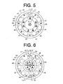
- Fig. 5 is a cross sectional view illustrating a pulley according to a fourth embodiment of the present invention;
- Fig. 6 is a cross sectional view illustrating a pulley according to a fifth embodiment of the present invention;
- Fig. 7A is a cross sectional view illustrating a pulley according to yet another embodiment of the present invention; and
- Fig. 7B is a cross sectional view taken along the line VII-VII in Fig. 7A.
- A first preferred embodiment of the present invention will now be described with reference to Figs. 1, 2A and 2B. Note that the left side and the right side of Fig. 1 are the front and the rear of the compressor in Fig. 1, respectively.
- As shown in FIG. 1, a compressor C includes a
cylinder block 11, afront housing 12 joined and fixed to the front end thereof, and arear housing 14 joined and fixed to the rear end of thecylinder block 11 via avalve plate assembly 13. Thecylinder block 11, thefront housing 12, thevalve plate assembly 13, and therear housing 14 constitute the housing of the compressor C. - A
crank chamber 15 is defined in a region surrounded by thecylinder block 11 and thefront housing 12. Adrive shaft 16, which is provided so as to penetrate thecrank chamber 15, is rotatably supported in the housing. - The front end of the
drive shaft 16 is arranged so as to penetrate a front wall of thefront housing 12 and protrude outside. The front end of thedrive shaft 16 is connected for operation to a vehicle engine E as an external drive source via apulley 17 as a rotation body (described later) and abelt 18 partially wound around thepulley 17. - A
lug plate 19 is fixed to thedrive shaft 16 so as to integrally rotate with thedrive shaft 16 in thecrank chamber 15. Thereby, thelug plate 19 has the same rotational central axis as thedrive shaft 16. Aswash plate 20 as a cam plate is housed in thecrank chamber 15. Theswash plate 20 is supported so as to be capable of sliding and inclining with respect to an axis of thedrive shaft 16. Theswash plate 20 is connected for operation to thelug plate 19 via ahinge mechanism 21 as will be described later. - The
hinge mechanism 21 includes a pair ofsupport arms 19A provided so as to protrude from the rear surface of thelug plate 19 toward the rear direction and a pair ofguide pins 20A provided so as to protrude from the front surface of theswash plate 20 toward the front direction. A pair of guide holes 19B are formed respectively at the distal portions of thesupport arms 19A, and aspherical portion 20B having a substantially spherical shape, which is formed at each distal portion of theguide pins 20A, is fitted into each of the guide holes 19B movably in a sliding manner. - The
swash plate 20 is capable of connecting to thelug plate 19 for operation via thehinge mechanism 21, rotating integrally with thelug plate 19 and thedrive shaft 16 by support of thedrive shaft 16, and can be inclined with respect to a rotational central axis of thedrive shaft 16 while sliding along the rotational central axis of thedrive shaft 16. - The minimum inclination angle of the
swash plate 20 is defined by acircular clip 22 fixed to thedrive shaft 16 and aspring 23 disposed between thecircular clip 22 and theswash plate 20. Note that the minimum inclination angle of theswash plate 20 indicates an inclination angle in the state where the angle made by theswash plate 20 and the rotational central axis of thedrive shaft 16 is closest to 90°. - A plurality of cylinder bores 24 (only one is shown in Fig. 1) are formed in the
cylinder block 11 in a penetrating manner along a direction of the rotational central axis of thedrive shaft 16. Single-head pistons 25 (compression member) are housed in thecylinder bores 24 for reciprocation. Front and rear openings of thecylinder bore 24 are closed by thepiston 25 and thevalve plate assembly 13, and a compression chamber, whose volume changes in accordance with the reciprocating motion of thepiston 25, is defined in thecylinder bore 24. Eachpiston 25 is firmly fixed to the outer periphery of theswash plate 20 via a pair ofshoes 26. With this configuration, the rotational motion of thedrive shaft 16 is converted into reciprocating motion or compression motion of eachpiston 25 via thelug plate 19, theswash plate 20, theshoes 26. - Note that piston type compression mechanism is constituted of the
drive shaft 16, thelug plate 19, theswash plate 20, thehinge mechanism 21, thepistons 25, and theshoes 26. Further, thelug plate 19, theswash plate 20, thehinge mechanism 21, and theshoes 26 constitute the conversion mechanism to convert the rotational motion of thedrive shaft 16 into the compression motion of thepistons 25. - A
suction chamber 27 and adischarge chamber 28 are defined and formed in therear housing 14. The front portions of thesuction chamber 27 and thedischarge chamber 28 are closed by thevalve plate assembly 13. Refrigerant gas (fluid) in thesuction chamber 27 is introduced into the cylinder bore 24 (compression chamber) by the movement of eachpiston 25 from the rear portion to the front portion via asuction port 29 with opening asuction valve 30, which are formed in thevalve plate assembly 13. The low pressure refrigerant gas introduced into the cylinder bore 24 is compressed to a predetermined pressure by the movement of thepiston 25 from the front portion to the rear portion, and is introduced into thedischarge chamber 28 via adischarge port 31 with opening adischarge valve 32, which are formed in thevalve plate assembly 13. - The
suction chamber 27 and thedischarge chamber 28 are connected by an external refrigerant circuit (not shown). The refrigerant discharged from thedischarge chamber 28 is introduced into the external refrigerant circuit. The external refrigerant circuit performs heat exchange using the refrigerant. The refrigerant discharged from the external refrigerant circuit is introduced into thesuction chamber 27, introduced into the cylinder bore 24, and compressed again. - The housing is provided with a
bleed passage 33 via which thecrank chamber 15 communicates with thesuction chamber 27. Additionally, the housing is provided with asupply passage 34 via which thedischarge chamber 28 communicates with thecrank chamber 15. Acontrol valve 35 disposed on thesupply passage 34 is capable of adjusting an opening degree of thesupply passage 34. - By adjusting an opening degree of the
control valve 35, the balance between an amount of high pressure refrigerant gas introduced into thecrank chamber 15 via thesupply passage 34 and an amount of gas discharged from thecrank chamber 15 via thebleed passage 33 are controlled, and thus crank chamber pressure Pc (inner pressure of the crank chamber 15) is determined. The differential pressure between the crank chamber pressure Pc and the inner pressure of the compression chamber via thepiston 25 is changed in accordance with variation of the crank pressure Pc, and the inclination angle of theswash plate 20 is varied. As a result, stroke distance of thepiston 25, that is, discharge capacity per one rotation of thedrive shaft 16 is adjusted. - Herein, while the
drive shaft 16 goes into one rotation, the state where the capacity of the compression chamber is the smallest is the state where thepiston 25 is positioned at the top dead center, and the state where the capacity of the compression chamber is the largest is the state where thepiston 25 is positioned at the bottom dead center. Then, a portion where thepiston 25 is positioned at the top dead center around the rotational central axis of thedrive shaft 16 is referred to as a top dead center portion around the rotational central axis of thedrive shaft 16, and a portion where thepiston 25 is positioned at the bottom dead center is referred to as a bottom dead center portion around the rotational central axis of thedrive shaft 16. - In the present embodiment, the
hinge mechanism 21 is provided at the top dead center portion around the rotational central axis of the drive shaft 16 (an upper portion of thedrive shaft 16 in Fig. 1). Specifically, a pair of thesupport arms 19A and a pair of thepins 20A are provided at the top dead center portion around the rotational central axis of thedrive shaft 16 with respect to thelug plate 19 and theswash plate 20, respectively. - In the
lug plate 19, acounter weight 19C for reducing the offset load of thelug plate 19 around the rotational central axis of thedrive shaft 16, which is caused by the mass of a pair of thesupport arms 19A, is provided at the bottom dead center portion around the rotational central axis of thedrive shaft 16. Further, in theswash plate 20, a counter weight 20C for reducing the offset load of theswash plate 20 around the rotational central axis of thedrive shaft 16, which is caused by the mass of a pair of thepins 20A, is provided at the bottom dead center portion around the rotational central axis of thedrive shaft 16. - As shown in Fig. 1 and Fig. 2B, the
pulley 17 is fixed to thedrive shaft 16 so as to integrally rotate with thedrive shaft 16 in the state where the pulley is rotatably supported by abearing 41 that is disposed on the outer circumferential surface of asupport cylinder 40 provided on a front outer wall surface of thefront housing 12. Thereby, thepulley 17 has the same rotational central axis as thedrive shaft 16. - As shown in Figs. 1, 2A, and 2B, the
pulley 17 includes apulley body 42 made of resin. Thepulley body 42 is provided with aboss 43 attached to an outer ring of thebearing 41 and a cylindricalbelt receiving portion 44 to which thebelt 18 is hooked. In thepulley 17, six recesses 45 (only one is shown in Fig. 1) as guide portions are formed in an area between theboss 43 and thebelt receiving portion 44. - The
recesses 45 are arranged at uniform intervals in a circumferential direction of thepulley 17. Further, three recesses 45 (afirst recess 45A, asecond recess 45B, athird recess 45C) among the sixrecesses 45 are arranged at the top dead center portion around the rotational central axis of thedrive shaft 16, and the remaining three recesses 45 (afourth recess 45D, afifth recess 45E, asixth recess 45F) are arranged at the bottom dead center portion around the rotational central axis of thedrive shaft 16. As shown in Fig. 2A, thefirst recess 45A, thesecond recess 45B and thethird recess 45C are disposed in a clockwise direction from the left portion of the drawing in order, at the top dead center portion around the rotational central axis of thedrive shaft 16. Furthermore, thefourth recess 45D, thefifth recess 45E and thesixth recess 45F are disposed in the clockwise direction from the right portion of the drawing in order, at the bottom dead center portion around the rotational central axis of thedrive shaft 16. - A
guide surface 46, whose sectional shape on a plane orthogonal to a rotational central axis of thepulley 17 is in an arc-shape, is formed on eachrecess 45. Theguide surface 46 constitutes a part of an inner circumferential surface of a virtual cylinder with a radius r1 whose center is an axis that is remote from the rotational central axis by a predetermined distance R1 and is substantially parallel with the rotational central axis. - Rollers 47 (the diameter of the
roller 47 is d1 and the mass per oneroller 47 is m1) as mass bodies are housed by one in four of the six recesses 45. In other words, therollers 47 are housed in the three recesses 45 (thefourth recess 45D, thefifth recess 45E, thesixth recess 45F) at the bottom dead center portion around the rotational central axis of thedrive shaft 16 and one recess 45 (thesecond recess 45B) at the top dead center portion around the rotational central axis of thedrive shaft 16. Eachroller 47 is made of metal (iron in the present embodiment) of the same material (the same density), and formed in a cylindrical shape of the same shape and the same size, and thus setting the same mass. - Each
roller 47 is housed in a state where it can roll in eachrecess 45 in the circumferential direction of theguide surface 46 along theguide surface 46. Eachroller 47 is prevented from falling outside each recess by aplate 48 fixed at the opening portion (front portion) of eachrecess 45 with screws, which is in a ring shape and made of resin. - When the vehicle engine E drives the compressor C, that is, during rotation of the
drive shaft 16, centrifugal force works on eachroller 47, and the roller is in the state where it contacts with the guide surface 46 (the state shown in Figs. 1, 2A and 2B). If torque fluctuation caused by torsional vibration (rotational vibration) of thedrive shaft 16 occurs in this state, eachroller 47 starts reciprocating motion in eachrecess 45 along the guide surface 46 (in the circumferential direction of the guide surface 46). Specifically, (center of gravity of) eachroller 47 performs pendulum motion whose center is the central axis of the inner circumferential surface of the virtual cylinder, where theguide surface 46 constitutes a part thereof. Therefore, eachroller 47 serves as a centrifugal pendulum when the vehicle engine E drives the compressor C. In the present embodiment, arrangement position, a size and a mass of therollers 47 in thepulley 17 are set in order to restrict the torque fluctuation (rotational vibration) by the pendulum motion of therollers 47. - Herein, description will be made for each of the above-described settings for the
rollers 47 that serve as the centrifugal pendulum. - The
rollers 47 serve to restrict the torque fluctuation (fluctuation width of the torque fluctuation) in frequency equal to the natural frequency of the rollers (centrifugal pendulum) 47. Therefore, the arrangement position, the size and the mass of therollers 47 in thepulley 17 are set such that the natural frequency of therollers 47 equals to the peak frequency of the torque fluctuation, so that the torque fluctuation at the peak is restricted and overall influence by the torque fluctuation is efficiently restricted. Note that the peak of the torque fluctuation indicates the peak of the fluctuation width in the torque fluctuation, that is, rotational order component. - The frequency of the torque fluctuation and the natural frequency of the
roller 47 are proportional to an angular velocity ω1 of thedrive shaft 16, which correlates with the rotational velocity of thedrive shaft 16. Further, the frequency of the torque fluctuation when the peak of the torque fluctuation of the compressor C appears is given by a product (ω1/2π) · N of a rotational velocity (=ω1/2π) of thedrive shaft 16 per unit time and the number of cylinders (the number of the cylinder bores 24) N. Note that, in the compressor C, experiments have found that the frequency of an nth largest (n is a natural number) peak among peaks of the torque fluctuation tends to show a value equivalent to the product n · (ω1/2π) · N. - On the other hand, the natural frequency of the
rollers 47 is given by a product of the rotational velocity (=ω1/2π) of thedrive shaft 16 per unit time and a square root value of a ratio R/r. Note that R mentioned here is a distance between the rotational central axis of the pulley 17 (a rotational body provided with a mass body that performs pendulum motion) and the central axis of the pendulum motion of the roller 47 (mass body), and r is a distance between the central axis of the pendulum motion of theroller 47 and the center of gravity of theroller 47. - Therefore, by setting the square root value of the ratio R/r equally to the value of the product n · N, it is possible to match the frequency of the nth largest peak in the torque fluctuation and the natural frequency of the
roller 47. This makes it possible to restrict the torque fluctuation in the frequency of the nth largest peak. In the present embodiment, accordingly, sizes of R and r are set to make the square root value of the ratio R/r equal to the value of the n · N in order to restrict the peak in the torque fluctuation. - To efficiently restrict the torque fluctuation by the pendulum motion of the
rollers 47, torque T around the rotational central axis of thepulley 17 worked by therollers 47 needs to be a size equal to the fluctuation width of the torque fluctuation to cope with the fluctuation. It is understood that the size of the torque T in the state where the frequency of the peak in the torque fluctuation and the natural frequency of theroller 47 have matched is given by the following equation.
T=m · (ωa)2 · (R+r) · R · φ
where m is a total mass (m=4 · m1) of all therollers 47, and ωa is an average angular velocity of theroller 47 when performing pendulum motion at a minute oscillating angle φ. - Note that, in the present embodiment, the central axis of the inner circumferential surface of the virtual cylinder, where the
guide surface 46 constitutes a part of the inner circumferential surface thereof, matches the central axis of the pendulum motion of the roller 47 (a fulcrum of the pendulum motion is on this central axis). Specifically, a distance R1 between the rotational central axis of thepulley 17 and the central axis of the inner circumferential surface of the virtual cylinder corresponds to the distance R. - Further, a distance between the central axis of the pendulum motion of the
roller 47 and the center of gravity of theroller 47 is equal to a numerical value where a half of a diameter d1 of theroller 47 is subtracted from the radius r1 of inner circumferential surface of the virtual cylinder. In other words, the difference {r1-(d1/2)} corresponds to the distance r. - Specifically, in the present embodiment, sizes of R1, r1 and d1 are set to make the square root value of the ratio R1/{r1-(d1/2)}, which corresponds to the square root value of the ratio R/r, equal to the value of the n · N in order to restrict the peak in the torque fluctuation.
- Note that, in the above-described pendulum motion, each kind of settings has been done on condition that the
roller 47 is a material particle where the mass concentrates on the center of gravity of theroller 47. Further, since the oscillating angle φ of theroller 47 in the pendulum motion is minute, during rotation of thedrive shaft 16, theroller 47 positions substantially at a center in the circumferential direction of thepulley 17 in eachrecess 45. - Next, description will be made for the operation of the compressor C that is constituted as described above.
- When power is supplied from the vehicle engine E to the
drive shaft 16 via thepulley 17, theswash plate 20 rotates together with thedrive shaft 16. With the rotation of theswash plate 20, eachpiston 25 reciprocates in a stroke corresponding to the inclination angle of theswash plate 20, and suction, compression and discharge of refrigerant are sequentially repeated in each cylinder bore 24. - Note that as the opening level of the
control valve 35 becomes small, an amount of the high-pressure refrigerant gas supplied from thedischarge chamber 28 to the crankchamber 15 via thesupply passage 34 becomes small. Then, the crank chamber pressure Pc reduces, the inclination angle of theswash plate 20 becomes large, and the discharge capacity of the compressor C becomes large. On the contrary, as the opening level of thecontrol valve 35 becomes large, the amount of the high-pressure refrigerant gas supplied from thedischarge chamber 28 to the crankchamber 15 via thesupply passage 34 becomes large. Then, the crank chamber pressure Pc increases, the inclination angle of theswash plate 20 becomes small, and the discharge capacity of the compressor C becomes small. - During the rotation of the
drive shaft 16, compression reactive force of refrigerant and reactive force based on the reciprocating motion of thepiston 25 are transmitted to thedrive shaft 16 via theswash plate 20 or thehinge mechanism 21, and thus the torsional vibration (rotational vibration) occurs in thedrive shaft 16. The torsional vibration generates the torque fluctuation. The torque fluctuation is a cause to generate resonance in the compressor C itself and between external equipments (such as the vehicle engine E and an auxiliary machine) connected to thepulley 17 for operation via thebelt 18 and the compressor C. - When the torque fluctuation is generated, the
rollers 47 provided for thepulley 17 begin pendulum motion. The torque worked around the rotational central axis of thepulley 17 by the pendulum motion works to restrict the torque fluctuation. - Further, the offset load of the
pulley 17 based on the fact that therollers 47 are arranged at the bottom dead center portion around the rotational central axis of thedrive shaft 16 more than the top dead center portion works to cancel the offset load of the conversion mechanism, which is caused by the fact that thehinge mechanism 21 is provided at the top dead center portion around the rotational central axis of thedrive shaft 16. - In the first preferred embodiment, the following effects are obtained.
- (1) The
pulley 17 is provided with therollers 47 that perform pendulum motion whose center is the axis that is remote from the rotational central axis of thepulley 17 by the predetermined distance R1 and is parallel with the rotational central axis. With this configuration, the pendulum motion of therollers 47 restricts the rotational vibration (the torque fluctuation), and the resonance generated in the compressor C and between the vehicle engine E connected to thepulley body 42 for operation via thebelt 18 and the compressor C are restricted. - (2) Since a structure (such as the roller 47) for restricting the rotational vibration is provided in the
pulley 17, means for restricting the rotational vibration does not need to be particularly provided inside the housing of the compressor C. In short, the housing of the compressor C becomes compact. Structure change of thepulley 17 can change (the order of) rotational order component that can be coped with and the size of the torque T without changing the structure of the housing and the compression mechanism. - (3) In the
pulley 17, therollers 47 are provided to cancel the offset load of the conversion mechanism around the rotational central axis of thedrive shaft 16. Therefore, vibration caused by the offset load of the conversion mechanism is reduced. Furthermore, a size and a weight of thecounter weights 19C and 20C provided for thelug plate 19 and theswash plate 20 can be small. As a result, the compressor C itself can be compact and lightweight. - (4) By disposing the
rollers 47 in a part ofrecesses 45 among a plurality of therecesses 45 provided at a uniform interval with each other in the circumferential direction of thepulley 17, a plurality of therollers 47 is arranged at an irregular interval in the circumferential direction. Thus, mass distribution of therollers 47 in thepulley 17 is set so as to be larger at the bottom dead center portion around the rotational central axis of thedrive shaft 16 than the top dead center portion. As a result, the offset load of the conversion mechanism around the rotational central axis of thedrive shaft 16 is cancelled.
A second preferred embodiment of the present invention will now be described with reference to Fig. 3. The second embodiment is one where the constitution of the rollers in the first embodiment is changed, and is in the same constitution with the first embodiment in other aspects. Therefore, constituent parts common to the first embodiment are added with the same reference numeral on the drawings and overlap of explanation is omitted.
As shown in Fig. 3, the rollers (mass body) are housed in all (six) recesses 45 in thepulley 17 of the present embodiment. Specifically, therollers 47 same as the ones in the first embodiment are housed in the recesses (thefourth recess 45D, thefifth recess 45E, thesixth recess 45F) at the bottom dead center portion around the rotational central axis of thedrive shaft 16 one by one. In addition, rollers 50 (a diameter of theroller 50 is d2) as a mass body, whose diameter is set to be smaller than that of theroller 47, are housed in the recesses (thefirst recess 45A, thesecond recess 45B, thethird recess 45C) at the top dead center portion around the rotational central axis of thedrive shaft 16 one by one.
The threerollers 50 are made of metal (iron in the present embodiment) of the same material (same density) as theroller 47. Further, eachroller 50 is formed in a cylindrical shape of the same shape and the same size, and thus setting the same mass with each other. In other words, eachroller 50 has smaller volume per unit than theroller 47, and therefore, has smaller mass. Accordingly, mass distribution of the rollers (mass body) in thepulley 17 is set so as to be larger at the bottom dead center portion around the rotational central axis of thedrive shaft 16 than the top dead center portion. The offset load of thepulley 17 based on the mass distribution works to cancel the offset load of the conversion mechanism, which is caused by the fact that thehinge mechanism 21 is provided at the top dead center portion around the rotational central axis of thedrive shaft 16.
In the present embodiment, a distance between the central axis of the pendulum motion of theroller 50 and the center of gravity of theroller 50 is equal to a numerical value where a half of a diameter d2 of theroller 50 is subtracted from the radius r1 of the inner circumferential surface of the virtual cylinder of theguide surface 46. In other words, the difference {r1-(d2/2)} corresponds to the distance r. The value of the ratio R/r regarding theroller 50 is smaller than that regarding theroller 47. Accordingly, theroller 50 copes with rotational order component of lower order than theroller 47. Specifically, the pendulum motion of theroller 50 restricts the torque fluctuation width in the rotational order component of lower order than the rotational order component corresponding to theroller 47.
In the second preferred embodiment, the following effects are obtained in addition to the same effects as the above-described effects (1) to (3). - (5) By changing the diameter (that is, volume) of a part of rollers among a plurality of the rollers from that of the other rollers, the mass per unit a part of rollers among a plurality of the rollers is made different from that of the other rollers. Thus, the mass distribution of the rollers in the
pulley 17 is set so as to be larger at the bottom dead center portion around the rotational central axis of thedrive shaft 16 than the top dead center portion. Therefore, the offset load of the conversion mechanism around the rotational central axis of thedrive shaft 16 is cancelled. - (6) The values of the ratio R/r in each roller (47, 50) can be made different from each other by the diameter difference between the
roller 50 and theroller 47. This arrangement can cope with a plurality of rotational order component in the rotational vibration. - (7) A rotational order component corresponding to the
rollers 47, which are arranged at the bottom dead center portion around the rotational central axis of thedrive shaft 16, is set in a higher order than the rotational order component corresponding to therollers 50, which are arranged at the top dead center portion. In the present embodiment, this is realized by setting the diameter d2 of theroller 50 smaller than the diameter d1 of theroller 47 and by making the value of the distance r regarding theroller 50 larger than the value of the distance r regarding theroller 47. In other words, setting the rotational order component corresponding to theroller 47 in the higher order than the rotational order component corresponding to theroller 50 is suitable for making the mass distribution at the bottom dead center portion around the rotational central axis of thedrive shaft 16 larger than that of the top dead center portion.
A third preferred embodiment of the present invention will now be described with reference to Fig. 4. The third embodiment is one where the constitution of the recesses in the second embodiment is changed, and is in the same constitution with the second embodiment in other aspects. Therefore, constituent parts common to the second embodiment are added with the same reference numeral on the drawings and overlap of explanation is omitted.
As shown in Fig. 4, in thepulley 17 of the present embodiment, the arrangement positions of the recesses (thefirst recess 45A, thesecond recess 45B, thethird recess 45C) in thepulley body 42 at the top dead center portion around the rotational central axis of thedrive shaft 16 and the shapes of the recesses are different from those in thepulley 17 of the second embodiment. Specifically, a radius r2 of the inner circumferential surface of the virtual cylinder that constitutes eachguide surface 46 of the recesses (thefirst recess 45A, thesecond recess 45B, thethird recess 45C) is set to be smaller than the radius r1 of the inner circumferential surface of the virtual cylinder that constitutes eachguide surface 46 of the recesses (thefourth recess 45D, thefifth recess 45E, thesixth recess 45F) at the bottom dead center portion around the rotational central axis of thedrive shaft 16. Further, a distance R2 between the central axis of the inner circumferential surface of the virtual cylinder regarding the recesses (thefirst recess 45A, thesecond recess 45B, thethird recess 45C) and the rotational central axis of the pulley 17 (equivalent to the distance R in the ratio R/r) is set to be smaller than the distance R1 regarding the recesses (thefourth recess 45D, thefifth recess 45E, thesixth recess 45F).
In the present embodiment, the distance r (distance r at the ratio R/r) regarding the recesses (thefirst recess 45A, thesecond recess 45B, thethird recess 45C) and therollers 50 cope with a difference {r2-(d2/2)}. In the present embodiment, the distances (radii) (R2, r2) are set such that values of ratio R/r in the recesses (thefirst recess 45A, thesecond recess 45B, thethird recess 45C) and the recesses (thefourth recess 45D, thefifth recess 45E, thesixth recess 45F) become equal. In other words, the both rollers (47, 50) of the present embodiment cope with only one rotational order component.
In the present embodiment, although the capacity of the recesses (thefirst recess 45A, thesecond recess 45B, thethird recess 45C) is smaller than the capacity of the recesses (thefourth recess 45D, thefifth recess 45E, thesixth recess 45F), lightened metal in the vicinity of eachrecess 45 prevents thepulley body 42 from having the offset load around the rotational central axis of thedrive shaft 16. Furthermore, in the present embodiment, diameters of thesupport cylinder 40, thebearing 41, and theboss 43 are set to be smaller comparing to the second embodiment in order to make the distance R2 regarding the recesses (thefirst recess 45A, thesecond recess 45B, thethird recess 45C) smaller than the distance R1 regarding the recesses (thefourth recess 45D, thefifth recess 45E, thesixth recess 45F).
In the present third embodiment, the following effects are obtained in addition to the effects same as the above-described effects (1) to (3) and (5). - (8) In the
pulley 17 of the present embodiment, a constitution is made such that the rollers are housed in all therecesses 45 and all the rollers cope with one rotational order component. Accordingly, a total mass of the rollers, which is capable of coping with one rotational order component, is relatively easily secured. Therefore, this constitution is particularly effective when controlling the torque fluctuation in one particular rotational order component in the case where the torque fluctuation width of the one particular rotational order component is prominently larger comparing to another rotational order component.
A fourth preferred embodiment of the present invention will now be described with reference to Fig. 5. The fourth embodiment is one where the numbers of the rollers and the recesses in the first embodiment is changed, and is in the same constitution with the first embodiment in other aspects. Therefore, constituent parts common to the first embodiment are added with the same reference numeral on the drawings and overlap of explanation is omitted.
As shown in Fig. 5, sevenrecesses 45 are provided for thepulley 17 of the present embodiment, and therollers 47 are housed in all therecesses 45. Therecesses 45 at the bottom dead center portion around the rotational central axis of thedrive shaft 16 are increased by one comparing to the first embodiment. Specifically, aseventh recess 45G is provided in addition to the recesses (thefourth recess 45D, thefifth recess 45E, thesixth recess 45F) at the bottom dead center portion around the rotational central axis of thedrive shaft 16. The values of distances (radii) R1, r1 and the value of the diameter d1 of theroller 47 regarding theseventh recess 45G are set equally to those of theother recesses 45 and therollers 47.
In the bottom dead center portion around the rotational central axis of thedrive shaft 16, the recesses (thefourth recess 45D, thefifth recess 45E, thesixth recess 45F, theseventh recess 45G) are arranged at uniform intervals with respect to the circumferential direction of thepulley 17. During the rotation of thepulley 17, therollers 47 housed in the recesses (thefourth recess 45D, thefifth recess 45E, thesixth recess 45F, theseventh recess 45G) do not position at the top dead center portion around the rotational central axis of thedrive shaft 16.
In the present fourth embodiment, the following effects are obtained in addition to the effects same as the above-described effects (1) to (3) and (8). - (9) The number of the
recesses 45 at the bottom dead center portion is increased with respect to the top dead center portion around the rotational central axis of thedrive shaft 16, all therecesses 45 house the mass bodies (rollers 47), and thus a plurality of the mass bodies (rollers 47) is arranged at an irregular interval in the circumferential direction of thepulley 17. With this arrangement, the mass distribution of the mass bodies (rollers 47) in thepulley 17 is set so as to be larger at the bottom dead center portion around the rotational central axis of thedrive shaft 16 than the top dead center portion. As a result, the offset load of the conversion mechanism around the rotational central axis of thedrive shaft 16 is cancelled.
A fifth preferred embodiment of the present invention will mow be described with reference to Fig. 6. The fifth embodiment is one where the numbers, the shapes and the arrangement positions of the rollers and the recesses in the third embodiment are changed, and is in the same constitution with the third embodiment in other aspects. Therefore, constituent parts common to the third embodiment are added with the same reference numeral on the drawings and overlap of explanation is omitted.
As shown in Fig. 6, eightrecesses 45 are provided for thepulley 17 of the present embodiment. The constitution of the recesses (thefirst recess 45A, thesecond recess 45B, thethird recess 45C) at the top dead center portion around the rotational central axis of thedrive shaft 16 is the same as the third embodiment. On the other hand, the number of therecesses 45 at the bottom dead center portion around the rotational central axis of thedrive shaft 16 is increased by two comparing to the third embodiment. Specifically, recesses (theseventh recess 45G,eighth recess 45H) are provided in addition to the recesses (thefourth recess 45D, thefifth recess 45E, thesixth recess 45F) at the bottom dead center portion around the rotational central axis of thedrive shaft 16. The recesses (thefourth recess 45D, thefifth recess 45E, thesixth recess 45F, theseventh recess 45G, theeighth recess 45H) are arranged at uniform intervals in the circumferential direction of thepulley 17.
The radius of the inner circumferential surface of the virtual cylinder regarding the recesses (thefourth recess 45D, thefifth recess 45E, thesixth recess 45F, theseventh recess 45G, theeighth recess 45H) are set equally to the radius r2 regarding the recesses (thefirst recess 45A, thesecond recess 45B, thethird recess 45C) (hereinafter, the radius regarding the recesses (thefourth recess 45D, thefifth recess 45E, thesixth recess 45F, theseventh recess 45G, theeighth recess 45H) is described as r2 as well). Further, a distance R3 between the central axis of the inner circumferential surface of the virtual cylinder regarding the recesses (thefourth recess 45D, thefifth recess 45E, thesixth recess 45F, theseventh recess 45G, theeighth recess 45H) and the rotational central axis of the pulley 17 (equivalent to the distance R in the ratio R/r) is set to be larger than the distance R2 regarding the recesses (thefirst recess 45A, thesecond recess 45B, thethird recess 45C).
In the present embodiment, therollers 50 having the same constitution as theroller 50 housed in the recesses (thefirst recess 45A, thesecond recess 45B, thethird recess 45C) in the third embodiment are housed in all therecesses 45 one by one. In the embodiment, the distance r (distance r at the ratio R/r) regarding all therecesses 45 and therollers 50 corresponds to the difference {r2-(d2/2)}. Since the distance R3 is set to be larger than the distance R2, the value of the ratio R/r regarding therollers 50 housed in the recesses (thefourth recess 45D, thefifth recess 45E, thesixth recess 45F, theseventh recess 45G, theeighth recess 45H) is larger than the one regarding therollers 50 housed in the recesses (thefirst recess 45A, thesecond recess 45B, thethird recess 45C). Therefore, therollers 50 at the bottom dead center portion around the rotational central axis of thedrive shaft 16 cope with the rotational order component of the higher order than therollers 50 at the top dead center.
In the fifth preferred embodiment, the following effects are obtained in addition to the effects same as the above-described effects (1) to (3) and (9). - (10) In a part of a plurality of the
rollers 50, a distance between the center of a pendulum motion and the rotational central axis of thepulley 17 is different from that of theother rollers 50. The difference of the distance (the difference between the distance R3 and the distance R2) enables to cope with a plurality of rotational order component in the rotational vibration. Further, in therollers 50 where the distance is relatively large (therollers 50 at the bottom dead center portion around the rotational central axis of the drive shaft 16), the larger number of arrangement and arrangement space can be easily secured for therollers 50 in the circumferential direction of thepulley 17 comparing to therollers 50 where the distance is relatively small (therollers 50 at the top dead center portion around the rotational central axis of the drive shaft 16). In other words, the mass distribution of therollers 50 around the rotational central axis of thedrive shaft 16 can be easily made to be irregular. - (11) The rotational order component corresponding to the
rollers 50 arranged at the bottom dead center portion around the rotational central axis of thedrive shaft 16 is set in the higher order than the rotational order component corresponding to therollers 50 arranged at the top dead center portion. In the present embodiment, this is realized by setting the distance R3 regarding therollers 50 at the bottom dead center portion around the rotational central axis of thedrive shaft 16 to be larger than the distance R2 regarding therollers 50 at the top dead center portion. Therefore, the larger number of arrangement and arrangement space can be easily secured for therollers 50 in the circumferential direction of thepulley 17 with regard to therollers 50 at the bottom dead center portion around the rotational central axis of thedrive shaft 16. In other words, setting the rotational order component corresponding to therollers 50 at the bottom dead center portion around the rotational central axis of thedrive shaft 16 in the higher order than the rotational order component corresponding to therollers 50 at the top dead center portion is suitable for making the mass distribution of therollers 50 at the bottom dead center portion to be larger than that of the top dead center portion. - Embodiments are not limited to the above-described ones, but may be in the following modes, for example.
- In alternative embodiments to the preferred embodiments, in the
pulley 17, if the mass distribution of the rollers (mass body) at the bottom dead center portion around the rotational central axis of thedrive shaft 16 is set larger than the one at the top dead center portion, the rotational order component corresponding to the rollers at the bottom dead center portion may be set at the lower order than the rotational order component corresponding to the rollers at the top dead center portion. - In alternative embodiments to the preferred embodiments, in the
pulley 17, if the mass distribution of the rollers (mass body) at the bottom dead center portion around the rotational central axis of thedrive shaft 16 is set to be larger than the one at the top dead center portion, the mass per unit of the rollers at the bottom dead center portion may be set to be smaller than the mass per unit of the rollers at the top dead center portion. - In alternative embodiments to the preferred embodiments, in the
pulley 17, if the mass distribution of the rollers (mass body) at the bottom dead center portion around the rotational central axis of thedrive shaft 16 is set to be larger than the one at the top dead center portion, the number of the rollers at the bottom dead center portion may be set to be smaller than the number of the rollers at the top dead center portion. - In alternative embodiments to the preferred embodiments, a length in a direction of the rotational central axis for a part of a plurality of the rollers (47, 50) may be different from the other rollers. Accordingly, the mass per unit for a part of a plurality of the rollers (47, 50) can be made different from the other rollers by the difference in lengths. Therefore, the mass difference can cancel the offset load of the conversion mechanism around the rotational central axis of the
drive shaft 16. According to the present structure, the mass per unit can be made different from each other even if the diameters of the rollers (47, 50) are set in a uniform size, for example. In this case, a structure is made as shown in Fig. 7. The structure of Fig. 7 is one where the number of therollers 47 and the length in the direction of the rotational central axis of a part of therollers 47 are changed in the first embodiment. Specifically, therollers 47 are housed in all therecesses 45. Further, the length (L2) in the direction of the rotational central axis of the recesses (thefourth recess 45D, thefifth recess 45E, thesixth recess 45F) is set to be longer than the length (L1) in the direction of the rotational central axis of the recesses (thefirst recess 45A, thesecond recess 45B, thethird recess 45C). Note that the diameters of all therollers 47 are set equally (d1). Thus, the mass distribution of therollers 47 in thepulley 17 is set to be larger at the bottom dead center portion around the rotational central axis of thedrive shaft 16 than the top dead center portion. - In alternative embodiments to the preferred embodiments, material for a part of a plurality of the rollers (47, 50) may be material having different density from the other rollers. This can make the mass per unit for a part of a plurality of the rollers (47, 50) different from the other rollers. Therefore, the mass difference can cancel the offset load of the conversion mechanism around the rotational central axis of the
drive shaft 16. According to the present structure, the mass per unit can be made different from each other even if the shape and the size of the rollers (47, 50) are the same, for example. - In alternative embodiments to the preferred embodiments, the rollers (47, 50) may be formed using copper, tungsten.
- In alternative embodiments to the preferred embodiments, the
pulley body 42 may be formed using metal. - In alternative embodiments to the preferred embodiments, in the
pulley body 42, the mass distribution of thepulley body 42 around the rotational central axis of thedrive shaft 16 may be adjusted by varying the shape of the lightened metal. - In alternative embodiments to the preferred embodiments, the mass body may be formed in a spherical shape.
- In the above-described embodiments, the rollers (47, 50) that roll along the
guide surface 46 of therecesses 45 formed in thepulley 17 are made to perform pendulum motion. In alternative embodiments to the preferred embodiments, the pulley may be provided with mass bodies that perform pendulum motion using a support shaft fixed to the pulley as a fulcrum. Furthermore, the mass body itself is provided with the support shaft, and the support shaft may be inserted into a hole formed on the pulley to support the mass body on the pulley in such a manner that pendulum motion can be performed. - In the above-described embodiments, a plurality of mass bodies is provided for the rotor. In alternative embodiments to the preferred embodiments, a structure where only one mass body is provided may be used. In this case, the one mass body is provided so as to cancel the offset load of the conversion mechanism around the rotational central axis of the
drive shaft 16. - In the above-described embodiments, the mass bodies are provided to cope with one or two rotational order component. In alternative embodiments to the preferred embodiments, the mass bodies may be structured to cope with three or more rotational order component.
- In the above-described embodiments, the ratio R/r is set to cope with the rotational order component in the rotational vibration that the compressor C generates. In alternative embodiments to the preferred embodiments, for example, the ratio R/r may be set in order to cope with the rotational order component in the rotational vibration that the vehicle engine E or the auxiliary machine (a rotary machine such as an oil pump for power steering), which are connected to the compressor C for operation via power transmission member such as the
belt 18, generates. - In alternative embodiments to the preferred embodiments, in the compressor C, means for assembly and positioning in the circumferential direction of the
drive shaft 16 between thepulley 17 and thedrive shaft 16 may be provided. With this means, working efficiency is improved when thepulley 17 is assembled on thedrive shaft 16. - In alternative embodiments to the preferred embodiments, the cylinder bores 24 in the compressor C may be set in any number. Generally, the number of the cylinder bores 24 is set to any of 3 to 7 for the compressor used in a vehicle air conditioner in many cases. Further, when the number of the cylinder bores 24 is set to 3, the torque fluctuation quantity of rotational vibration in the
drive shaft 16 tends to increase comparing to the case where the number is set to 4 or more. In other words, rotational vibration restricting effect by the mass bodies works particularly efficiently in the compressor where the number of the cylinder bores 24 is set to 3. - In alternative embodiments to the preferred embodiments, the
pulley 17 may be provided for a double-head piston type compressor where double-head pistons perform compression operation in the cylinder bores provided on both front and rear sides sandwiching the crank chamber, not for a single-head piston type compressor where single-head piston performs compression operation. - In alternative embodiments to the preferred embodiments, the compressor C may be a type in which a cam plate is supported by the drive shaft so as to rotate and wobble with respect to the drive shaft, which is a wobble type compressor, for example, instead of the structure in which the cam plate (swash plate 20) integrally rotates with the
drive shaft 16. - In all the above-described embodiments, an application example of the invention to a piston type compressor in which pistons perform reciprocating motion is shown. In alternative embodiments to the preferred embodiments, the invention may be applied for a rotary type compressor such as a scroll type compressor.
- In alternative embodiments to the preferred embodiments, a sprocket and a gear may be applied as the rotation body other than the pulley.
- In alternative embodiments to the preferred embodiments, the rotation body may be applied for a rotational member housed in the housing of the compressor C. For example, the mass body may be provided for the
lug plate 19 connected for operation to thedrive shaft 16 in the housing or for another member particularly provided, and thus the rotational vibration on thedrive shaft 16 may be restricted. - In alternative embodiments to the preferred embodiments, the central axis of the pendulum motion of the mass body may not necessarily be parallel with the rotational central axis of the rotation body provided with the mass body. In this case, the central axis of the pendulum motion may be inclined with respect to the rotational central axis of the rotation body within a scope where a desired effect can be obtained in restriction of the transferred torque fluctuation. Note that a distance Rs (described below) is set as a distance between the center of the pendulum motion and the rotational central axis of the rotation body, for example, in the state where the central axis of the pendulum motion is inclined with respect to the rotational central axis of the rotation body. Specifically, a distance between an intersectional point made by a plane, which is perpendicular to the central axis of the pendulum motion and passes the center of gravity of the mass body, and the central axis of the pendulum motion, and the rotational central axis of the rotation body is set as the distance Rs.
- Therefore, the present examples and embodiments are to be considered as illustrative and not restrictive and the invention is not to be limited to the details given herein but may be modified within the scope of the appended claims.
- A compressor includes a drive shaft, a conversion mechanism, a rotation body and a mass body. The conversion mechanism converts rotational motion of the drive shaft into compression motion of a compression member in a compression mechanism. The rotation body is provided with the drive shaft so as to integrally rotate with the drive shaft. The drive shaft and the rotation body have a rotational central axis. The mass body is provided with the rotation body. The mass body performs pendulum motion whose center is an axis that is remote from the rotational central axis by a predetermined distance and that is substantially parallel with the rotational central axis. The compressor is characterized in that the mass body is provided to cancel offset load of the conversion mechanism around the rotational central axis of the drive shaft.
Claims (12)
- A compressor including a drive shaft, a conversion mechanism, a rotation body and a mass body, the conversion mechanism converting rotational motion of the drive shaft into compression motion of a compression member in a compression mechanism, the rotation body being provided with the drive shaft so as to integrally rotate with the drive shaft, the drive shaft and the rotation body having a rotational central axis, the mass body being provided with the rotation body, the mass body performing pendulum motion whose center is an axis that is remote from the rotational central axis by a predetermined distance and that is substantially parallel with the rotational central axis, characterized in that:the mass body is provided to cancel offset load of the conversion mechanism around the rotational central axis of the drive shaft.
- The compressor according to claim 1, wherein a plurality of the mass bodies is provided and is arranged at an irregular interval in a circumferential direction of the rotation body.
- The compressor according to claims 1 or 2, wherein a plurality of the mass bodies is provided, mass per unit of a part of the mass bodies being different from that of the other mass bodies.
- The compressor according to claim 3, wherein volume of a part of the mass bodies is different from that of the other mass bodies.
- The compressor according to claim 4, wherein the mass body is a cylindrical-shaped roller movably disposed along a guide surface, the guide surface being formed on the rotation body and having an arc-shaped sectional surface, a diameter of a part of the mass bodies being different from that of the other mass bodies.
- The compressor according to claims 4 or 5, wherein the mass body is the cylindrical-shaped roller movably disposed along a guide surface, the guide surface being formed on the rotation body and having an arc-shaped sectional surface, a length in the axial direction of a part of the mass bodies being different from that of the other mass bodies.
- The compressor according to any of claims 3 to 6, wherein the material of a part of the mass bodies has different density from the other mass bodies.
- The compressor according to any one of claims 1 to 7, wherein a plurality of the mass bodies is provided, a part of the mass bodies has a different distance between the center of pendulum motion of the mass bodies and the rotational central axis from the other mass bodies.
- The compressor according to any one of claims 1 to 8, wherein the compression mechanism is a piston type compression mechanism including a plurality of pistons as the compression member around the rotational central axis, the conversion mechanism including a lug plate, a swash plate and a shoe, the lug plate also having the rotational central axis, the lug plate being fixed to the drive shaft so as to integrally rotate with the drive shaft, the swash plate being coupled to the lug plate so as to integrally rotate with the lug plate via a hinge mechanism, the hinge mechanism being provided at a top dead center portion around the rotational central axis, the shoe being located between the piston and the swash plate, the swash plate being supported by the hinge mechanism so as to incline with respect to the rotational central axis, mass distribution of the mass bodies being set to be larger at a bottom dead center portion than the top dead center portion.
- The compressor according to claim 9, wherein a plurality of the mass bodies is provided, the number of mass bodies being set to be larger at the bottom dead center portion than the top dead center portion on the rotation body.
- The compressor according to claims 9 or 10, wherein a plurality of the mass bodies is provided, mass per unit of the mass bodies arranged at the bottom dead center portion being set to be larger than the mass per unit of the mass bodies arranged at the top dead center portion.
- The compressor according to any of claims 9 to 11, wherein a plurality of the mass bodies is provided, a rotational order component corresponding to the mass bodies arranged at the bottom dead center portion being set at a higher order than a rotational order component corresponding to the mass bodies arranged at the top dead center portion.
Applications Claiming Priority (2)
| Application Number | Priority Date | Filing Date | Title |
|---|---|---|---|
| JP2002060501A JP2003254233A (en) | 2002-03-06 | 2002-03-06 | Compressor |
| JP2002060501 | 2002-03-06 |
Publications (2)
| Publication Number | Publication Date |
|---|---|
| EP1342920A2 true EP1342920A2 (en) | 2003-09-10 |
| EP1342920A3 EP1342920A3 (en) | 2003-12-10 |
Family
ID=27751136
Family Applications (1)
| Application Number | Title | Priority Date | Filing Date |
|---|---|---|---|
| EP03005001A Withdrawn EP1342920A3 (en) | 2002-03-06 | 2003-03-05 | Compressor balancing system |
Country Status (2)
| Country | Link |
|---|---|
| EP (1) | EP1342920A3 (en) |
| JP (1) | JP2003254233A (en) |
Cited By (2)
| Publication number | Priority date | Publication date | Assignee | Title |
|---|---|---|---|---|
| WO2008009446A1 (en) * | 2006-07-19 | 2008-01-24 | Knorr-Bremse Systeme für Nutzfahrzeuge GmbH | System with a compressor and with a consumer in a motor vehicle |
| CN109209817A (en) * | 2018-11-20 | 2019-01-15 | 泉州苗亿自动化机械有限公司 | A kind of soundproof oil free air compressor |
Families Citing this family (2)
| Publication number | Priority date | Publication date | Assignee | Title |
|---|---|---|---|---|
| JP2017133549A (en) * | 2016-01-26 | 2017-08-03 | トヨタ自動車株式会社 | Torsional vibration reduction device |
| JP2026060278A (en) * | 2024-09-27 | 2026-04-08 | 本田技研工業株式会社 | Auxiliary equipment and engine |
Family Cites Families (7)
| Publication number | Priority date | Publication date | Assignee | Title |
|---|---|---|---|---|
| JP3832012B2 (en) * | 1997-03-31 | 2006-10-11 | 株式会社豊田自動織機 | Variable capacity compressor |
| JPH11159453A (en) * | 1997-11-28 | 1999-06-15 | Toyota Autom Loom Works Ltd | Torsional resonance dampting structure of driving system in compressor |
| DE10004125A1 (en) * | 2000-01-31 | 2001-08-02 | Mannesmann Sachs Ag | Torsional vibration damper |
| DE10013652A1 (en) * | 2000-03-18 | 2001-09-20 | Mannesmann Sachs Ag | Oscillation dampener has radially-adjustable transverse mass balance operating within guide slots |
| DE50111158D1 (en) * | 2000-08-09 | 2006-11-16 | Hasse & Wrede Gmbh | ROTARY VIBRATION |
| JP2003013995A (en) * | 2001-06-28 | 2003-01-15 | Toyota Industries Corp | Power transmitting mechanism and compressor |
| JP2003065392A (en) * | 2001-08-23 | 2003-03-05 | Toyota Industries Corp | Rotating body and rotating machine |
-
2002
- 2002-03-06 JP JP2002060501A patent/JP2003254233A/en active Pending
-
2003
- 2003-03-05 EP EP03005001A patent/EP1342920A3/en not_active Withdrawn
Cited By (4)
| Publication number | Priority date | Publication date | Assignee | Title |
|---|---|---|---|---|
| WO2008009446A1 (en) * | 2006-07-19 | 2008-01-24 | Knorr-Bremse Systeme für Nutzfahrzeuge GmbH | System with a compressor and with a consumer in a motor vehicle |
| US8337169B2 (en) | 2006-07-19 | 2012-12-25 | Knorr-Bremse Systeme Fuer Nutzfahrzeuge Gmbh | System with a compressor and with a consumer in a motor vehicle |
| CN109209817A (en) * | 2018-11-20 | 2019-01-15 | 泉州苗亿自动化机械有限公司 | A kind of soundproof oil free air compressor |
| CN109209817B (en) * | 2018-11-20 | 2023-09-29 | 泉州苗亿自动化机械有限公司 | Mute oil-free air compressor |
Also Published As
| Publication number | Publication date |
|---|---|
| EP1342920A3 (en) | 2003-12-10 |
| JP2003254233A (en) | 2003-09-10 |
Similar Documents
| Publication | Publication Date | Title |
|---|---|---|
| EP1286050A2 (en) | Rotary damper | |
| EP1491769A1 (en) | A device having a pulsation reducing structure, a passage forming body and compressor | |
| KR20020073301A (en) | Compressor and pulley for compressor | |
| US20030000783A1 (en) | Rotary machine | |
| US20020002840A1 (en) | Motor-driven compressor | |
| EP1270941A2 (en) | Power transmission mechanism and compressor | |
| US20030000377A1 (en) | Rotor and compressor | |
| US6572342B2 (en) | Variable capacity compressor and method of manufacturing | |
| US20030002991A1 (en) | Compressor | |
| KR102797290B1 (en) | Compressor and air conditioning system having the same | |
| EP1118769A2 (en) | Swash plate type compressor | |
| US5882179A (en) | Compressor with bearing between the drive shaft and the swash-plate boss | |
| JP3744861B2 (en) | Compressor | |
| JP2002340097A (en) | Rotor and compressor | |
| JP2003254233A (en) | Compressor | |
| KR20240052145A (en) | Scroll compressor | |
| US20040253121A1 (en) | Rotary machine | |
| JP2002340143A (en) | Compressor | |
| KR20150122359A (en) | Swash plate type compressor with reduction function of noise | |
| CN114370385B (en) | Reciprocating compressor | |
| JP2000291541A (en) | Layout method for variable displacement compressor and manufacture thereof | |
| US20010043866A1 (en) | Electric compressor | |
| JP2521933Y2 (en) | Variable displacement compressor for air conditioning | |
| JP2003049903A (en) | Dynamic damper and rotary machine | |
| KR100715261B1 (en) | Variable displacement swash plate compressor |
Legal Events
| Date | Code | Title | Description |
|---|---|---|---|
| PUAI | Public reference made under article 153(3) epc to a published international application that has entered the european phase |
Free format text: ORIGINAL CODE: 0009012 |
|
| 17P | Request for examination filed |
Effective date: 20030305 |
|
| AK | Designated contracting states |
Kind code of ref document: A2 Designated state(s): AT BE BG CH CY CZ DE DK EE ES FI FR GB GR HU IE IT LI LU MC NL PT RO SE SI SK TR |
|
| AX | Request for extension of the european patent |
Extension state: AL LT LV MK |
|
| PUAL | Search report despatched |
Free format text: ORIGINAL CODE: 0009013 |
|
| AK | Designated contracting states |
Kind code of ref document: A3 Designated state(s): AT BE BG CH CY CZ DE DK EE ES FI FR GB GR HU IE IT LI LU MC NL PT RO SE SI SK TR |
|
| AX | Request for extension of the european patent |
Extension state: AL LT LV MK |
|
| AKX | Designation fees paid |
Designated state(s): DE FR IT |
|
| STAA | Information on the status of an ep patent application or granted ep patent |
Free format text: STATUS: THE APPLICATION IS DEEMED TO BE WITHDRAWN |
|
| 18D | Application deemed to be withdrawn |
Effective date: 20051001 |