EP1342897A1 - Viertakt-Ottomotor mit variabler Ventilsteuerung - Google Patents
Viertakt-Ottomotor mit variabler Ventilsteuerung Download PDFInfo
- Publication number
- EP1342897A1 EP1342897A1 EP02100230A EP02100230A EP1342897A1 EP 1342897 A1 EP1342897 A1 EP 1342897A1 EP 02100230 A EP02100230 A EP 02100230A EP 02100230 A EP02100230 A EP 02100230A EP 1342897 A1 EP1342897 A1 EP 1342897A1
- Authority
- EP
- European Patent Office
- Prior art keywords
- closing
- opening
- camshaft
- valves
- intake valves
- Prior art date
- Legal status (The legal status is an assumption and is not a legal conclusion. Google has not performed a legal analysis and makes no representation as to the accuracy of the status listed.)
- Granted
Links
- 238000000034 method Methods 0.000 claims abstract description 18
- 230000003111 delayed effect Effects 0.000 claims description 10
- 239000000446 fuel Substances 0.000 description 12
- 230000008901 benefit Effects 0.000 description 6
- 239000007789 gas Substances 0.000 description 6
- 238000011161 development Methods 0.000 description 5
- 230000009977 dual effect Effects 0.000 description 5
- 239000000203 mixture Substances 0.000 description 5
- 238000010586 diagram Methods 0.000 description 4
- 238000013461 design Methods 0.000 description 3
- 238000005516 engineering process Methods 0.000 description 3
- 230000007704 transition Effects 0.000 description 3
- 238000002485 combustion reaction Methods 0.000 description 2
- 230000006872 improvement Effects 0.000 description 2
- 238000002347 injection Methods 0.000 description 2
- 239000007924 injection Substances 0.000 description 2
- 238000012423 maintenance Methods 0.000 description 2
- 238000004519 manufacturing process Methods 0.000 description 2
- 230000010363 phase shift Effects 0.000 description 2
- 238000005086 pumping Methods 0.000 description 2
- 238000004458 analytical method Methods 0.000 description 1
- 238000013459 approach Methods 0.000 description 1
- 239000003054 catalyst Substances 0.000 description 1
- 230000003197 catalytic effect Effects 0.000 description 1
- 230000006835 compression Effects 0.000 description 1
- 238000007906 compression Methods 0.000 description 1
- 230000001934 delay Effects 0.000 description 1
- 238000007865 diluting Methods 0.000 description 1
- 239000003085 diluting agent Substances 0.000 description 1
- 238000006073 displacement reaction Methods 0.000 description 1
- 230000002349 favourable effect Effects 0.000 description 1
- 238000009434 installation Methods 0.000 description 1
- 230000007246 mechanism Effects 0.000 description 1
- 230000008092 positive effect Effects 0.000 description 1
- 230000009467 reduction Effects 0.000 description 1
- 230000004044 response Effects 0.000 description 1
Images


Classifications
-
- F—MECHANICAL ENGINEERING; LIGHTING; HEATING; WEAPONS; BLASTING
- F02—COMBUSTION ENGINES; HOT-GAS OR COMBUSTION-PRODUCT ENGINE PLANTS
- F02D—CONTROLLING COMBUSTION ENGINES
- F02D13/00—Controlling the engine output power by varying inlet or exhaust valve operating characteristics, e.g. timing
- F02D13/02—Controlling the engine output power by varying inlet or exhaust valve operating characteristics, e.g. timing during engine operation
- F02D13/0203—Variable control of intake and exhaust valves
- F02D13/0215—Variable control of intake and exhaust valves changing the valve timing only
- F02D13/0219—Variable control of intake and exhaust valves changing the valve timing only by shifting the phase, i.e. the opening periods of the valves are constant
-
- F—MECHANICAL ENGINEERING; LIGHTING; HEATING; WEAPONS; BLASTING
- F01—MACHINES OR ENGINES IN GENERAL; ENGINE PLANTS IN GENERAL; STEAM ENGINES
- F01L—CYCLICALLY OPERATING VALVES FOR MACHINES OR ENGINES
- F01L1/00—Valve-gear or valve arrangements, e.g. lift-valve gear
- F01L1/34—Valve-gear or valve arrangements, e.g. lift-valve gear characterised by the provision of means for changing the timing of the valves without changing the duration of opening and without affecting the magnitude of the valve lift
-
- F—MECHANICAL ENGINEERING; LIGHTING; HEATING; WEAPONS; BLASTING
- F01—MACHINES OR ENGINES IN GENERAL; ENGINE PLANTS IN GENERAL; STEAM ENGINES
- F01L—CYCLICALLY OPERATING VALVES FOR MACHINES OR ENGINES
- F01L13/00—Modifications of valve-gear to facilitate reversing, braking, starting, changing compression ratio, or other specific operations
- F01L13/0015—Modifications of valve-gear to facilitate reversing, braking, starting, changing compression ratio, or other specific operations for optimising engine performances by modifying valve lift according to various working parameters, e.g. rotational speed, load, torque
-
- F—MECHANICAL ENGINEERING; LIGHTING; HEATING; WEAPONS; BLASTING
- F02—COMBUSTION ENGINES; HOT-GAS OR COMBUSTION-PRODUCT ENGINE PLANTS
- F02D—CONTROLLING COMBUSTION ENGINES
- F02D13/00—Controlling the engine output power by varying inlet or exhaust valve operating characteristics, e.g. timing
- F02D13/02—Controlling the engine output power by varying inlet or exhaust valve operating characteristics, e.g. timing during engine operation
- F02D13/0203—Variable control of intake and exhaust valves
- F02D13/0207—Variable control of intake and exhaust valves changing valve lift or valve lift and timing
-
- F—MECHANICAL ENGINEERING; LIGHTING; HEATING; WEAPONS; BLASTING
- F02—COMBUSTION ENGINES; HOT-GAS OR COMBUSTION-PRODUCT ENGINE PLANTS
- F02D—CONTROLLING COMBUSTION ENGINES
- F02D13/00—Controlling the engine output power by varying inlet or exhaust valve operating characteristics, e.g. timing
- F02D13/02—Controlling the engine output power by varying inlet or exhaust valve operating characteristics, e.g. timing during engine operation
- F02D13/0223—Variable control of the intake valves only
- F02D13/0234—Variable control of the intake valves only changing the valve timing only
-
- F—MECHANICAL ENGINEERING; LIGHTING; HEATING; WEAPONS; BLASTING
- F02—COMBUSTION ENGINES; HOT-GAS OR COMBUSTION-PRODUCT ENGINE PLANTS
- F02D—CONTROLLING COMBUSTION ENGINES
- F02D13/00—Controlling the engine output power by varying inlet or exhaust valve operating characteristics, e.g. timing
- F02D13/02—Controlling the engine output power by varying inlet or exhaust valve operating characteristics, e.g. timing during engine operation
- F02D13/0269—Controlling the valves to perform a Miller-Atkinson cycle
-
- F—MECHANICAL ENGINEERING; LIGHTING; HEATING; WEAPONS; BLASTING
- F01—MACHINES OR ENGINES IN GENERAL; ENGINE PLANTS IN GENERAL; STEAM ENGINES
- F01L—CYCLICALLY OPERATING VALVES FOR MACHINES OR ENGINES
- F01L1/00—Valve-gear or valve arrangements, e.g. lift-valve gear
- F01L1/02—Valve drive
- F01L1/04—Valve drive by means of cams, camshafts, cam discs, eccentrics or the like
- F01L1/047—Camshafts
- F01L1/053—Camshafts overhead type
- F01L2001/0537—Double overhead camshafts [DOHC]
-
- F—MECHANICAL ENGINEERING; LIGHTING; HEATING; WEAPONS; BLASTING
- F01—MACHINES OR ENGINES IN GENERAL; ENGINE PLANTS IN GENERAL; STEAM ENGINES
- F01L—CYCLICALLY OPERATING VALVES FOR MACHINES OR ENGINES
- F01L2800/00—Methods of operation using a variable valve timing mechanism
-
- F—MECHANICAL ENGINEERING; LIGHTING; HEATING; WEAPONS; BLASTING
- F02—COMBUSTION ENGINES; HOT-GAS OR COMBUSTION-PRODUCT ENGINE PLANTS
- F02B—INTERNAL-COMBUSTION PISTON ENGINES; COMBUSTION ENGINES IN GENERAL
- F02B2275/00—Other engines, components or details, not provided for in other groups of this subclass
- F02B2275/32—Miller cycle
-
- F—MECHANICAL ENGINEERING; LIGHTING; HEATING; WEAPONS; BLASTING
- F02—COMBUSTION ENGINES; HOT-GAS OR COMBUSTION-PRODUCT ENGINE PLANTS
- F02D—CONTROLLING COMBUSTION ENGINES
- F02D15/00—Varying compression ratio
- F02D15/04—Varying compression ratio by alteration of volume of compression space without changing piston stroke
-
- Y—GENERAL TAGGING OF NEW TECHNOLOGICAL DEVELOPMENTS; GENERAL TAGGING OF CROSS-SECTIONAL TECHNOLOGIES SPANNING OVER SEVERAL SECTIONS OF THE IPC; TECHNICAL SUBJECTS COVERED BY FORMER USPC CROSS-REFERENCE ART COLLECTIONS [XRACs] AND DIGESTS
- Y02—TECHNOLOGIES OR APPLICATIONS FOR MITIGATION OR ADAPTATION AGAINST CLIMATE CHANGE
- Y02T—CLIMATE CHANGE MITIGATION TECHNOLOGIES RELATED TO TRANSPORTATION
- Y02T10/00—Road transport of goods or passengers
- Y02T10/10—Internal combustion engine [ICE] based vehicles
- Y02T10/12—Improving ICE efficiencies
Definitions
- the invention relates to a four-stroke gasoline engine with phase-adjustable valve actuators for opening and closing the intake valves and exhaust valves.
- the invention further relates to a method for controlling such a motor.
- gasoline engines Internal combustion engines with spark ignition (“gasoline engines”) used in automobiles are mainly operated with a stoichiometric air / fuel mixture, which allows very efficient aftertreatment of emissions and throttling for load control.
- Gasoline is used almost exclusively as fuel.
- the fuel loss associated with throttling and stoichiometric operation at part load in these engines can be reduced by lean operation.
- This lean operation can be either homogeneous or stratified direct injection type. In either case, the NO x emissions leaving the engine cannot be treated by a conventional three-way catalytic converter. For this reason, lean-burn NO x traps (LNT) have been developed, by means of which lean exhaust gases can be treated.
- LNT lean-burn NO x traps
- Camshaft adjustment is a well-known technology that is increasingly being used in the production of gasoline engines with double overhead camshafts. If the opening and closing times of the coupled valves are shifted equally with an adjustment of the camshaft, one speaks of a "dual same" adjustment (Dual Equal VCT). For engines with a single camshaft, the dual same variable camshaft control improves engine emissions and fuel consumption. A strategy for phase control of such camshafts is described in Stein et al. (Dual Equal VCT - A Variable Camshaft Timing Strategy for Improved Fuel Economy and Emissions, SAE Technical Paper 950975).
- the fuel consumption at part load is increased by adding diluting gas to the mixture (late closing of the exhaust valve and opening of the intake valve), increasing the effective expansion ratio (late opening of the exhaust valve) and reduction of pumping losses by reducing the effective displacement (late closing of the intake valves) improved. All of this is accomplished by delaying the opening of both the exhaust and intake valves at part load.
- the limitations of this method are that the improvement in fuel economy is concentrated in the lower half of the load range.
- the Atkinson cycle requires only an increased compression ratio and late closing of the intake valves (see Blakey, S., et al., "A Design and Experimental Study of an Otto Atkinson Cycle Engine Using Late Intake Valve Closing", SAE Technical Paper 910451).
- additional design changes are often made on the intake side of the engine in order to obtain an optimal torque curve of the engine at full load.
- the four-stroke gasoline engine according to the invention contains a first valve actuator for opening and closing the exhaust valves and optionally for opening the intake valves, wherein the first valve actuator has a first adjusting device, via which its phase is adjusted and thus the opening and closing of the exhaust valves can be delayed or brought forward. Furthermore, the gasoline engine contains a second valve actuator, which is used exclusively for closing the intake valves, preferably all intake valves of a row of cylinders, and which has a second adjusting device for changing the phase position of the closing time.
- Such a four-stroke gasoline engine has the advantage that it allows very flexible control of the engine with only two valve actuators and only two associated adjustment devices, which enables optimal operation both at part load and at full load. Examples of the operating modes that are possible hereby are presented below in connection with the method according to the invention.
- the gasoline engine can be used to perform a dual, identical valve control, in which intake valves and exhaust valves are adjusted in parallel, and operation can be carried out in an Atkinson cycle with a delayed closing of the intake valve.
- the separate setting option for the phase of closing the intake valve can also functionally be used as an early closing of the intake valve compared to the standard program, whereby the amount of mixture entering the cylinder at full load can be controlled.
- the range of the phase variation for the closing of the intake valve does not have to be particularly large, so that the phase adjustment can be achieved in particular with conventional, inexpensive camshafts. Small valve lifts are avoided, so that there are lower requirements for precision, which in turn has a positive effect on the manufacturing costs, the maintenance effort and the robustness.
- intermediate areas of the setting are largely avoided, which improves the driving properties.
- the first valve actuator can advantageously be formed by a first camshaft and the second valve actuator by a second camshaft.
- Camshafts have the advantage of being well-known, widespread, proven and Shafts have the advantage of being known, widespread, proven and cost-effective means for variable valve control.
- one of the camshafts mentioned is coupled to a camshaft drive via its associated adjusting device and coupled to this other camshaft via the other adjusting device of the other camshaft.
- the first (alternatively: second) camshaft is thus driven by the drive, the interposed first (second) adjusting device permitting a phase shift of the first (second) camshaft relative to the drive.
- the first (second) camshaft then transfers its rotation to the second (first) adjusting element, which drives the second (first) camshaft with the phase shift set there.
- Such a structure can be implemented in a very compact manner, since the drive operates the camshafts in a quasi-cascade manner with the intermediate adjusting elements.
- the first valve actuator is also coupled to the inlet valves in order to be able to open them.
- the first valve actuator performs three functions, namely opening and closing the exhaust valves and opening the intake valves.
- the corresponding gasoline engine therefore only needs two adjustment elements - such as two camshafts - for the entire control of the valves.
- the four-stroke gasoline engine contains a third valve actuator for (exclusive) opening of the intake valves.
- the exhaust valves can be actuated independently of the intake valves, with the intake valves additionally opening and closing via separate valve actuators and therefore being adjustable independently.
- the aforementioned third valve actuator is preferably formed by a third camshaft.
- the third camshaft is preferably operatively coupled to a drive and furthermore via the first adjusting device with the first camshaft for actuating the exhaust valves and via the second adjusting device coupled to the second camshaft, which closes the intake valve.
- This configuration can be realized in a very compact manner, since the rotary drive is passed on from one camshaft to the other in a favorable manner.
- the invention further relates to a method for controlling a four-stroke gasoline engine of the type described above.
- the method is characterized in that the closing of the intake valves is delayed or advanced according to the power required by the engine during full load operation. Such a separate delay or early adjustment of the closing of the intake valves is possible because they are operated with their own valve actuator. Furthermore, the position of the opening and closing of the exhaust valves is adjusted to the speed at full load, provided that the exhaust valves can be adjusted separately from the opening of the intake valve.
- the opening and closing of the exhaust valves and the opening of the intake valves are delayed or adjusted late at partial load of the engine.
- the closing of the inlet valves is adjusted late by about twice the amount of the aforementioned adjustment. This can improve fuel consumption by adding diluent gas to the mixture, increasing the effective expansion ratio and reducing pumping losses.
- the closing of the intake valves can be delayed when the engine is idling. This is possible regardless of the adjustment of the other valve times, since a separate valve actuator is provided for closing the intake valves. If the exhaust valves can be adjusted independently of the opening of the intake valve, the opening and closing of the exhaust valves is preferably brought forward when idling.
- a four-stroke gasoline engine has a third adjusting element, which is provided for opening the intake valves.
- the opening and closing of the intake valves is adjusted early or late according to the required engine power, while that The opening and closing of the exhaust valves is adjusted late depending on the speed.
- the opening and closing of the exhaust valves and the closing of the intake valves are retarded when the engine is at partial load and the intake valves are firmly and not adjusted.
- the advantages also result here in reduced.
- FIG. 1 shows schematically a first possibility for a valve control according to the invention on a four-stroke gasoline engine.
- This valve control contains a first camshaft 1, the cam (not shown) opening EVO and Control the EVC closing of the cylinder bank exhaust valves (not shown) and the opening IVO of the cylinder bank intake valves (not shown).
- the camshaft 1 is driven in a known manner by a drive 8 which drives a wheel 5.
- the drive 8 can be, for example, a toothed belt coupled to the crankshaft of the gasoline engine.
- the wheel 5 is in turn coupled to the camshaft 1 via an adjusting device 3, wherein the adjusting device 3 can be designed in a known manner and allows the phase angle between the wheel 5 and the camshaft 1 to be adjusted.
- a gear 7 is arranged which drives a further gear 6.
- the latter gear wheel 6 is coupled to the second camshaft 2 via a second adjusting device 4, which extends parallel and adjacent to the first camshaft 1.
- the second camshaft 2 only controls the closing IVC of the intake valves. Due to the cascade arrangement of the camshafts 1, 2, an adjustment of the adjusting device 3 affects both camshafts.
- the splitting of the opening and closing of valves on two camshafts is possible, for example, with valve mechanisms as disclosed in US Pat. No. 5,178,105 or DE 43 22 480.
- FIG. 2 shows a preferred type of engine control in three valve lift diagrams, which is possible with the system shown in FIG. 1.
- the top diagram a shows the control of the valves at full load.
- the outlet valves are opened and closed without adjustment on curve 13, which corresponds to the normal operation of these valves (dashed curve 11 in FIG. 2b) in a conventional gasoline engine. Since the opening of the intake valves is controlled by the same camshaft 1 as the exhaust valves, this is also unadjusted and takes place shortly before the top dead center TDC of the piston between the exhaust stroke and the intake stroke.
- the second adjusting element 4 By a separate actuation of the second adjusting element 4 (FIG. 1), the closing time IVC of the intake valve can be varied in accordance with the curve family 14, so that the amount of mixture in the cylinder can be adjusted as required.
- Figure 2b shows the control at partial load of the engine.
- a late adjustment of the first camshaft 1 (FIG. 1) delays the opening and closing of the exhaust valves in accordance with curve 15 and the opening of the intake valve IVO. Furthermore, the closing IVC of the intake valve via the second camshaft 2 (FIG. 1) is delayed to a maximum, so that the course along curve 16 results for the intake valves as a whole.
- the dashed curve 12 shows the "normal" intake valve lift in a conventional gasoline engine.
- Figure 2c shows the control when the engine is idling.
- the camshaft 1 is operated in advance, so that the exhaust valves move in accordance with the "normal" curve 17 and the intake valve IVO is opened at the standard time. This minimizes the residual gas and ensures that the engine runs regularly.
- the second camshaft 2 is operated in a late adjustment for closing the inlet valve IVC as late as possible.
- the transition from the state according to FIG. 2b) to 2c) can be achieved simply by actuating the adjusting device 3 (FIG. 1), since the two camshafts hang from it in a cascade shape.
- FIG. 3 shows an alternative embodiment of a valve control for a four-stroke gasoline engine, three camshafts 101, 102 and 110 being arranged parallel to and adjacent to one another.
- the first camshaft 101 is only coupled to the exhaust valves in order to control their opening EVO and closing EVC.
- the second camshaft 102 is only coupled to the intake valves in order to control their closing IVC.
- the third camshaft 110 is also only coupled to the intake valves to control their opening IVO.
- the camshafts are rotated starting from a drive 108, which acts on a gear 109 at the end of the third camshaft 110 and on a gear 105 on the first camshaft 110.
- the gear 105 drives the first camshaft 101 via a first adjusting device 103.
- the latter has a further gearwheel 107 which interacts with a gearwheel 106 of the second camshaft 102.
- the latter gear 106 causes the second camshaft 102 to rotate via the second adjusting device 104.
- the structure described enables a very compact, coupled drive of the three camshafts, the third camshaft 110 being coupled directly and without adjustment to the drive 108, while the first camshaft 101 and the second camshaft 102 each have their own adjusting members 103 and 104, respectively the third camshaft are angularly coupled.
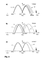
- FIG. 4 the control options that can be realized with a valve control according to FIG. 3 are shown schematically in valve lift diagrams.
- the opening and closing of the exhaust valves is adjusted more late according to curve 115 at partial load than at full load.
- the closing of the intake valve IVC is also delayed in accordance with curve 116.
Landscapes
- Engineering & Computer Science (AREA)
- Mechanical Engineering (AREA)
- General Engineering & Computer Science (AREA)
- Chemical & Material Sciences (AREA)
- Combustion & Propulsion (AREA)
- Valve Device For Special Equipments (AREA)
- Output Control And Ontrol Of Special Type Engine (AREA)
Abstract
Description
- Die Erfindung betrifft einen Viertakt-Ottomotor mit phasenverstellbaren Ventilstellgliedern zum Öffnen und Schließen der Einlaßventile und Auslaßventile. Ferner betrifft die Erfindung ein Verfahren zur Steuerung eines derartigen Motors.
- In Automobilen verwendete Brennkraftmaschinen mit Fremdzündung ("Ottomotoren") werden hauptsächlich mit einer stöchiometrischen Luft-Kraftstoff-Mischung betrieben, welche eine sehr effiziente Nachbehandlung der Emissionen und eine Drosselung zur Lastregelung erlaubt. Als Kraftstoff wird dabei fast ausschließlich Benzin verwendet. Die bei diesen Motoren mit der Drosselung und dem stöchiometrischen Betrieb bei Teillast verbundenen Kraftstoffverluste können durch einen mageren Betrieb verringert werden. Dieser magere Betrieb kann entweder vom Typ homogen oder vom Typ geschichtet mit Direkteinspritzung sein. In beiden Fällen können die den Motor verlassenden NOx-Emissionen nicht durch einen herkömmlichen Dreiwegekatalysator behandelt werden. Aus diesem Grunde sind Magerbetrieb-NOx-Fallen (LNT) entwickelt worden, mittels derer magere Abgase behandelt werden können. Der Nachteil derartiger, auf Magerbetrieb-NOx-Fallen basierender Systeme besteht darin, daß diese sehr viel teurer als Systeme mit herkömmlichen Dreiwegekatalysatoren sind. Im Falle der geschichteten Direkteinspritzung sind ferner die Systeme für Luftzufuhr, Kraftstoffzufuhr, Abgasrückführung und Zündung insgesamt sehr viel komplexer und daher teurer als bei üblichen Motoren.
- Ein alternativer "stöchiometrischer" Ansatz zur Verbesserung des Kraftstoffverbrauches besteht darin, kleinere Motoren mit einem Turbolader (booster) zu versehen. Jedoch sind auch hier die Zusatzkosten für den Turbolader, den Zwischenkühler und deren Einrichtung erheblich.
- Für niedrigpreisige Motoren kommen daher die vorstehend genannten Technologien praktisch nicht in Frage. Für diese Motoren ist eine variable Nockenwellensteuerung sinnvoller. Die damit erzielbaren Verbesserungen in der Kraftstoffausnutzung konzentrieren sich jedoch auf den Bereich geringerer Lasten.
- Bei der Nockenwellen-Verstellung handelt es sich um eine bekannte Technologie, die zunehmend bei der Produktion von Benzinmotoren mit doppelten obenliegenden Nockenwellen eingesetzt wird. Wenn mit einer Verstellung der Nockenwelle die Öffnungs- und Schließzeiten der angekoppelten Ventile gleichermaßen verschoben werden, spricht man von einer "dual gleichen" Verstellung (Dual Equal VCT). Bei Motoren mit einer einzigen Nockenwelle verbessert die dual gleiche variable Nockenwellensteuerung die Motoremissionen und den Kraftstoffverbrauch. Eine Strategie zur Phasensteuerung derartiger Nockenwellen wird bei Stein et al. (Dual Equal VCT - A Variable Camshaft Timing Strategy for Improved Fuel Economy and Emissions, SAE Technical Paper 950975) erläutert. Der Kraftstoffverbrauch bei Teillast wird durch Hinzufügung von verdünnendem Gas zur Mischung (spätes Schließen des Auslaßventils und Öffnen des Einlaßventils), durch Erhöhung des effektiven Expansionsverhältnisses (spätes Öffnen des Auslaßventils) sowie die Reduzierung der Pumpverluste durch Reduzierung des effektiven Hubraumes (spätes Schließen der Einlaßventile) verbessert. Dies alles wird erreicht durch eine Verzögerung des Öffnens sowohl der Auslaß- als auch der Einlaßventile bei Teillast. Die Einschränkungen dieses Verfahrens bestehen jedoch darin, daß die Verbesserung der Kraftstoffausnutzung auf die untere Hälfte des Lastbereiches konzentriert ist.
- Darüber hinaus ist eine als "Atkinsonzyklus" bezeichnete Steuerungstechnik bekannt, durch welche die Motoreffizienz insbesondere bei höheren Lasten gesteigert wird. Eine Definition und Analyse eines Otto-Atkinsonzyklus, der ein variables Schließen der Einlaßventile und ein veränderliches Brennkammervolumen erfordert, findet sich bei Luria et al. (The Otto-Atkinson engine, a new concept in automotive economy, SAE Technical Paper 820352) und Boggs et al. (The Otto-Atkinson engine - Fuel Economy and Emission Results and Hardware Design, SAE Technical Paper 950089). In der einfachsten Form erfordert der Atkinsonzyklus nur ein erhöhtes Kompressionsverhältnis und ein spätes Schließen der Einlaßventile (vgl. Blakey, S., et al., "A Design and Experimental Study of an Otto Atkinson Cycle Engine Using Late Intake Valve Closing", SAE Technical Paper 910451). In der Praxis werden dabei häufig zusätzliche Konstruktionsänderungen auf der Einlaßseite des Motors vorgenommen, um eine optimale Drehmomentkurve des Motors bei Vollast zu erhalten.
- Weiterhin sind mechanische Ventilstellglieder mit einer hohen Flexibilität hinsichtlich der Öffnungs- und Schließzeitpunkte sowie des Ventilhubes bekannt, welche einen Betrieb eines Ottomotors ohne Drosselklappen ermöglichen sollen. Die Steuerung der Zylinderfüllung über den Ventilhub erfordert dabei jedoch eine große mechanische Präzision in der Ausführung, damit es bei kleinen Hüben nicht zu Ungleichheiten zwischen den verschiedenen Zylindern kommt. Diese Anforderungen verteuern die entsprechenden Systeme, verkomplizieren ihre Wartung und erhöhen die Störanfälligkeit. Weiterhin durchlaufen derartige Systeme beim Übergang von großen Ventilhüben mit herkömmlichen Öffnungszeiten bei Vollast zu kurzen Ventilhüben und Öffnungszeiten bei Teillast stets einen Zwischenbereich, welcher keine funktionellen Vorteile bietet. Da während des üblichen Fahrbetriebes eines Fahrzeuges zahlreiche Übergänge stattfinden, werden die genannten Zwischenbereiche häufig durchlaufen, was dem Fahrer den Eindruck einer verzögerten Systemantwort vermittelt.
- Vor diesem Hintergrund bestand eine Aufgabe der vorliegenden Erfindung darin, ein robustes und kostengünstiges System und Verfahren zur variablen Steuerung der Einlaß- und Auslaßventile eines Ottomotors bereitzustellen.
- Diese Aufgabe wird durch einen Viertakt-Ottomotor mit den Merkmalen des Anspruchs 1 sowie durch ein Verfahren mit den Merkmalen des Anspruchs 8 gelöst.
- Vorteilhafte Ausgestaltungen sind in den Unteransprüchen enthalten.
- Der erfindungsgemäße Viertakt-Ottomotor enthält ein erstes Ventilstellglied zum Öffnen und Schließen der Auslaßventile und gegebenenfalls zum Öffnen der Einlaßventile, wobei das erste Ventilstellglied eine erste Verstelleinrichtung aufweist, über welche seine Phase verstellt und damit das Öffnen und Schließen der Auslaßventile verzögert beziehungsweise vorgezogen werden kann. Weiterhin enthält der Ottomotor ein zweites Ventilstellglied, das ausschließlich zum Schließen der Einlaßventile dient, vorzugsweise aller Einlaßventile einer Zylinderreihe, und das eine zweite Verstelleinrichtung zur Veränderung der Phasenlage des Schließzeitpunktes aufweist.
- Ein derartiger Viertakt-Ottomotor hat den Vorteil, daß dieser mit nur zwei Ventilstellgliedern und nur zwei zugehörigen Verstelleinrichtungen eine sehr flexible Ansteuerung des Motors erlaubt, welche sowohl bei Teillast als auch bei Vollast einen optimalen Betrieb ermöglicht. Beispiele für die hiermit möglichen Betriebsmodi werden nachstehend in Zusammenhang mit dem erfindungsgemäßen Verfahren dargestellt.
- Insbesondere kann mit dem Ottomotor eine dual gleiche Ventilsteuerung vorgenommen werden, bei welcher Einlaßventile und Auslaßventile parallel verstellt werden, und es kann der Betrieb in einem Atkinsonzyklus mit einem verzögerten Schließen des Einlaßventils erfolgen. Die separate Einstellmöglichkeit der Phase des Schließens des Einlaßventils kann dabei funktionell auch als ein gegenüber dem Standardprogramm frühes Schließen des Einlaßventils eingesetzt werden, wodurch sich die in den Zylinder bei Vollast eintretende Gemischmenge steuern läßt. Der Bereich der Phasenvariation für das Schließen des Einlaßventils muß dabei nicht besonders groß sein, so daß sich die Phasenverstellung insbesondere mit herkömmlichen, kostengünstigen Nockenwellen erzielen läßt. Dabei werden kleine Ventilhübe vermieden, so daß geringere Anforderungen an die Präzision bestehen, was sich wiederum positiv auf die Herstellungskosten, den Wartungsaufwand und die Robustheit auswirkt. Weiterhin werden Zwischenbereiche der Einstellung weitgehend vermieden, wodurch sich die Fahreigenschaften verbessern.
- Das erste Ventilstellglied kann vorteilhaft durch eine erste Nockenwelle und das zweite Ventilstellglied durch eine zweite Nockenwelle gebildet werden. Nockenwellen haben den Vorteil, bekannte, weitverbreitete, bewährte und wellen haben den Vorteil, bekannte, weitverbreitete, bewährte und kostengünstige Mittel zur variablen Ventilsteuerung zu sein.
- Gemäß einer Weiterbildung des Ottomotors ist eine der genannten Nockenwellen über ihre zugehörige Verstelleinrichtung mit einem Nockenwellen-Antrieb gekoppelt und über die andere Verstelleinrichtung der anderen Nockenwelle mit dieser anderen Nockenwelle gekoppelt. Bei dieser Konfiguration wird somit die erste (alternativ: zweite) Nockenwelle von dem Antrieb angetrieben, wobei die zwischengeschaltete erste (zweite) Verstelleinrichtung eine Phasenverschiebung der ersten (zweiten) Nockenwelle relativ zum Antrieb erlaubt. Die erste (zweite) Nockenwelle überträgt dann ihre Drehung auf das zweite (erste) Verstellglied, welches mit der dort eingestellten Phasenverschiebung die zweite (erste) Nockenwelle antreibt. Ein derartiger Aufbau läßt sich sehr kompakt realisieren, da der Antrieb die Nokkenwellen quasi kaskadenförmig mit den zwischengeschalteten Verstellgliedern betreibt.
- Gemäß einer bevorzugten Ausgestaltung der Erfindung ist das erste Ventilstellglied auch mit den Einlaßventilen gekoppelt, um diese öffnen zu können. Das heißt, daß das erste Ventilstellglied drei Funktionen übernimmt, nämlich das Öffnen und Schließen der Auslaßventile sowie das Öffnen der Einlaßventile. Der entsprechende Ottomotor kommt daher mit nur zwei Verstellgliedern - wie zum Beispiel zwei Nockenwellen - für die gesamte Steuerung der Ventile aus.
- Bei einer alternativen Ausgestaltung des Viertakt-Ottomotors enthält dieser ein drittes Ventilstellglied zum (ausschließlichen) Öffnen der Einlaßventile. Vorteilhaft hieran ist, daß die Auslaßventile unabhängig von den Einlaßventilen betätigt werden können, wobei bei den Einlaßventilen zusätzlich das Öffnen und Schließen über separate Ventilstellglieder erfolgt und daher unabhängig einstellbar ist.
- Das vorstehend genannte dritte Ventilstellglied wird vorzugsweise von einer dritten Nockenwelle gebildet. Dabei ist die dritte Nockenwelle vorzugsweise mit einem Antrieb wirksam gekoppelt und weiterhin über die erste Verstelleinrichtung mit der ersten Nockenwelle zur Betätigung der Auslaßventile und über die zweite Verstelleinrichtung mit der zweiten Nockenwelle gekoppelt, welche das Einlaßventil schließt. Diese Konfiguration läßt sich sehr kompakt realisieren, da der Drehantrieb in günstiger Weise von einer Nockenwelle auf die anderen weitergeleitet wird.
- Die Erfindung betrifft weiterhin ein Verfahren zur Steuerung eines Viertakt-Ottomotors der vorstehend erläuterten Art. Das Verfahren ist dadurch gekennzeichnet, daß bei Vollastbetrieb das Schließen der Einlaßventile entsprechend der vom Motor geforderten Leistung verzögert oder vorgezogen wird. Eine derartige separate Verzögerung oder Frühverstellung des Schließens der Einlaßventile ist möglich, da diese mit einem eigenen Ventilstellglied betrieben werden. Ferner wird bei Vollast die Lage des Öffnens und Schließens der Auslaßventile der Drehzahl angepaßt, sofern sich die Auslaßventile separat vom Öffnen des Einlaßventils verstellen lassen.
- Gemäß einer Weiterbildung des Verfahrens wird bei Teillast des Motors das Öffnen und Schließen der Auslaßventile und das Öffnen der Einlaßventile verzögert bzw. nach Spät verstellt. Das Schließen der Einlaßventile wird dagegen um etwa den doppelten Betrag der vorhergenannten Verstellung nach Spät verstellt. Hierdurch läßt sich der Kraftstoffverbrauch verbessern, da Verdünnungsgas zum Gemisch hinzugefügt wird, das effektive Expansionsverhältnis erhöht wird und die Pumpverluste verringert werden.
- Weiterhin kann bei dem Verfahren im Leerlauf des Motors das Schließen der Einlaßventile verzögert werden. Dies ist unabhängig von der Verstellung der übrigen Ventilzeiten möglich, da für das Schließen der Einlaßventile ein eigenes Ventilstellglied vorgesehen ist. Sofern sich die Auslaßventile unabhängig vom Öffnen des Einlaßventils verstellen lassen, wird im Leerlauf vorzugsweise das Öffnen und Schließen der Auslaßventile vorgezogen.
- In einer Weiterbildung des Verfahrens weist ein Viertakt-Ottomotor ein drittes Verstellglied auf, welches zum Öffnen der Einlaßventile vorgesehen ist. Bei Vollast des Motors wird nun das Öffnen und Schließen der Einlaßventile entsprechend der geforderten Motorleistung nach Früh oder auch Spät verstellt, während das Öffnen und Schließen der Auslaßventile gleichzeitig drehzahlabhängig nach Spät verstellt wird.
- Gemäß einer Weiterbildung des Verfahrens wird bei Teillast des Motors und festem, nicht verstellten Öffnen der Einlaßventile sowohl das Öffnen und Schließen der Auslaßventile als auch das Schließen der Einlaßventile nach Spät verstellt. Die Vorteile ergeben sich auch hier in verringertem.
- In einer Weiterbildung des Verfahrens wird im Leerlauf des Motors das Schließen des Einlaßventile nach Spät verstellt, während das Öffnen und Schließen der Auslaßventile nach Früh verschoben wird.
- Im Folgenden wird die Erfindung mit Hilfe der Figuren beispielhaft näher erläutert. Es zeigen:
- Fig. 1
- schematisch eine erste Ausgestaltung einer Ventilsteuerung mit zwei Nockenwellen;
- Fig. 2
- den Ventilhub eines Auslaßventils und eines Einlaßventils in Abhängigkeit von dem Kurbelwellenwinkel bei der erfindungsgemäßen Ansteue rung einer Konfiguration gemäß Figur 1;
- Fig. 3
- eine zweite Ausgestaltung einer erfindungsgemäßen Ventilsteuerung mit drei Nockenwellen; und
- Fig. 4
- in einer Darstellung entsprechend Figur 2 den Ventilhub eines Auslaßventils und eines Einlaßventils in Abhängigkeit vom Kurbelwellenwinkel bei der erfindungsgemäßen Ansteuerung einer Konfiguration gemäß Figur 3.
- In Figur 1 ist schematisch eine erste Möglichkeit für eine erfindungsgemäße Ventilsteuerung an einem Viertakt-Ottomotor dargestellt. Diese Ventilsteuerung enthält eine erste Nockenwelle 1, deren Nocken (nicht dargestellt) das Öffnen EVO und Schließen EVC der Auslaßventile einer Zylinderreihe (nicht dargestellt) sowie das Öffnen IVO der Einlaßventile (nicht dargestellt) der Zylinderreihe steuern. Der Antrieb der Nockenwelle 1 erfolgt in bekannter Weise durch einen Antrieb 8, welcher ein Rad 5 antreibt. Der Antrieb 8 kann zum Beispiel ein mit der Kurbelwelle des Ottomotors gekoppelter Zahnriemen sein. Das Rad 5 ist wiederum über eine Verstelleinrichtung 3 mit der Nockenwelle 1 gekoppelt, wobei die Verstelleinrichtung 3 in bekannter Weise ausgestaltet sein kann und eine Verstellung des Phasenwinkels zwischen dem Rad 5 und der Nockenwelle 1 erlaubt.
- An dem dem Rad 5 und der ersten Verstelleinrichtung 3 gegenüberliegenden Ende der Nockenwelle 1 ist ein Zahnrad 7 angeordnet, welches ein weiteres Zahnrad 6 antreibt. Letzteres Zahnrad 6 ist über eine zweite Verstelleinrichtung 4 mit der zweiten Nockenwelle 2 gekoppelt, welche sich parallel und benachbart zur ersten Nockenwelle 1 erstreckt. Die zweite Nockenwelle 2 steuert ausschließlich das Schließen IVC der Einlaßventile. Aufgrund der kaskadenförmigen Anordnung der Nockenwellen 1, 2 wirkt sich eine Verstellung der Verstelleinrichtung 3 auf beide Nockenwellen aus. Die Aufspaltung des Öffnens und Schließens von Ventilen auf zwei Nockenwellen ist zum Beispiel mit Ventilmechanismen möglich, wie sie in der US 5 178 105 oder der DE 43 22 480 offenbart sind.
- Figur 2 zeigt in drei Ventilhub-Diagrammen eine bevorzugte Art der Motorsteuerung, die mit dem in Figur 1 gezeigten System möglich ist. Das oberste Diagramm a) zeigt die Ansteuerung der Ventile bei Vollast. Das Öffnen und Schließen der Auslaßventile erfolgt in diesem Falle ohne Verstellung auf der Kurve 13, welche dem Normalbetrieb dieser Ventile (gestrichelte Kurve 11 in Figur 2b) bei einem herkömmlichen Ottomotor entspricht. Da das Öffnen der Einlaßventile von derselben Nockenwelle 1 wie die Auslaßventile gesteuert wird, ist auch dieses unverstellt und findet kurz vor dem oberen Totpunkt TDC des Kolbens zwischen dem Ausstoßtakt und dem Ansaugtakt statt. Durch eine separate Betätigung des zweiten Verstellgliedes 4 (Figur 1) kann der Schließzeitpunkt IVC des Einlaßventils entsprechend der Kurvenschar 14 variiert werden, so daß die sich im Zylinder befindliche Gemischmenge nach Bedarf eingestellt werden kann.
- Figur 2b) zeigt die Ansteuerung bei Teillast des Motors. Durch eine Spätverstellung der ersten Nockenwelle 1 (Figur 1) wird das Öffnen und Schließen der Auslaßventile entsprechend Kurve 15 sowie das Öffnen des Einlaßventils IVO verzögert. Ferner wird das Schließen IVC des Einlaßventils über die zweite Nockenwelle 2 (Figur 1) maximal verzögert, so daß sich für die Einlaßventile insgesamt der Verlauf entlang der Kurve 16 ergibt. Die gestrichelte Kurve 12 zeigt den "normalen" Einlaßventilhub bei einem herkömmlichen Ottomotor.
- Figur 2c) zeigt die Ansteuerung im Leerlauf des Motors. Die Nockenwelle 1 wird hierbei in Frühverstellung betrieben, so daß sich die Auslaßventile entsprechend der "normalen" Kurve 17 bewegen und das Öffnen des Einlaßventils IVO zum Standard-Zeitpunkt stattfindet. Dies minimiert den Restgasanteil und sorgt so für einen regelmäßigen Lauf des Motors. Die zweite Nockenwelle 2 wird in Spätverstellung für ein möglichst spätes Schließen IVC des Einlaßventils betrieben. Der Übergang vom Zustand nach Figur 2b) zu 2c) kann allein durch eine Betätigung der Verstelleinrichtung 3 (Figur 1) erfolgen, da die beiden Nockenwellen kaskadenförmig hieran hängen.
- Figur 3 zeigt eine alternative Ausgestaltung einer Ventilsteuerung für einen Viertakt-Ottomotor, wobei drei Nockenwellen 101, 102 und 110 parallel zueinander und benachbart angeordnet sind.
- Die erste Nockenwelle 101 ist in diesem Falle nur mit den Auslaßventilen gekoppelt, um deren Öffnen EVO und Schließen EVC zu steuern. Die zweite Nockenwelle 102 ist ähnlich wie bei Figur 1 nur mit den Einlaßventilen gekoppelt, um deren Schließen IVC zu steuern. Die dritte Nockenwelle 110 ist ebenfalls nur mit den Einlaßventilen gekoppelt, um deren Öffnen IVO zu steuern.
- Die Drehung der Nockenwellen erfolgt ausgehend von einem Antrieb 108, welcher auf ein Zahnrad 109 am Ende der dritten Nockenwelle 110 und auf ein Zahnrad 105 an der ersten Nockenwelle 110 wirkt. Das Zahnrad 105 treibt über eine erste Verstelleinrichtung 103 die erste Nockenwelle 101 an.
- An dem dem genannten Rad 109 gegenüberliegenden Ende der dritten Nockenwelle 110 weist diese ein weiteres Zahnrad 107 auf, welches mit einem Zahnrad 106 der zweiten Nockenwelle 102 zusammenwirkt. Das letztgenannte Zahnrad 106 bewirkt über die zweite Verstelleinrichtung 104 die Drehung der zweiten Nockenwelle 102.
- Durch den geschilderten Aufbau wird ein sehr kompakter, gekoppelter Antrieb der drei Nockenwellen möglich, wobei die dritte Nockenwelle 110 direkt und ohne Verstellmöglichkeit mit dem Antrieb 108 gekoppelt ist, während die erste Nockenwelle 101 und die zweite Nockenwelle 102 jeweils über eigene Verstellglieder 103 beziehungsweise 104 mit der dritten Nockenwelle winkelmäßig gekoppelt sind.
- In Figur 4 sind in Ventilhub-Diagrammen die Steuerungsmöglichkeiten schematisch dargestellt, die sich mit einer Ventilsteuerung entsprechend Figur 3 verwirklichen lassen.
- Der Betrieb bei Vollast des Motors erfolgt gemäß Figur 4a), wobei die Steuerung der Auslaßventile entsprechend der Kurve 113 stattfindet, die gegenüber der Standardkurve 111 (herkömmlicher Ottomotor) drehzahlabhängig nach spät verstellt ist. Das Schließen IVC des Einlaßventils wird durch das Verstellglied 104 (Figur 3) entsprechend den Bedürfnissen der Motorleistung variiert, so daß sich die entsprechende Kurvenschar 114 ergibt. Da das Öffnen IVO der Einlaßventile von der dritten Nockenwelle 110 (Figur 3) ohne eine Verstellmöglichkeit gesteuert wird, ist es in allen drei Diagrammen gegenüber der Standardkurve 112 (herkömmlicher Ottomotor) unverschoben.
- Gemäß Figur 4b) wird bei Teillast das Öffnen und Schließen der Auslaßventile entsprechend der Kurve 115 stärker nach spät verstellt als bei Vollast. Das Schließen IVC des Einlaßventils erfolgt entsprechend der Kurve 116 ebenfalls verzögert.
- Im Leerlauf (Figur 4c) wird das Öffnen und Schließen der Auslaßventile entsprechend der Kurve 117 frühverstellt, um den Restgasanteil zu minimierten, während das Schließen IVC des Einlaßventils gemäß der Kurve 118 wie bei Figur 4b) möglichst spät stattfindet.
Claims (13)
- Viertakt-Ottomotor, gekennzeichnet durch:
ein erstes Ventilstellglied (1, 101) mit einer ersten Verstelleinrichtung (3, 103) zum Öffnen (EVO) und Schließen (EVC) der Auslaßventile; und
ein zweites Ventilstellglied (2, 102) mit einer zweiten Verstelleinrichtung (4, 104), das ausschließlich dem Schließen (IVC) der Einlaßventile dient. - Viertakt-Ottomotor nach Anspruch 1,
dadurch gekennzeichnet, daß
das erste Ventilstellglied durch eine erste Nockenwelle (1, 101) und das zweite Ventilstellglied durch eine zweite Nockenwelle (2, 102) gebildet wird. - Viertakt-Ottomotor nach Anspruch 2,
dadurch gekennzeichnet, daß
eine der Nockenwellen (1) über die zugehörige Verstelleinrichtung (3) mit einem Antrieb (8) und über die andere Verstelleinrichtung (4) mit der anderen Nockenwelle (2) gekoppelt ist. - Viertakt-Ottomotor nach einem der Ansprüche 1 bis 3,
dadurch gekennzeichnet, daß
das erste Ventilstellglied (1) mit den Einlaßventilen gekoppelt ist, um diese zu öffnen. - Viertakt-Ottomotor nach einem der Ansprüche 1 bis 3,
dadurch gekennzeichnet, daß
dieser ein drittes Ventilstellglied (110) zum Öffnen (IVO) der Einlaßventile aufweist. - Viertakt-Ottomotor nach Anspruch 5,
dadurch gekennzeichnet, daß
das dritte Ventilstellglied durch eine dritte Nockenwelle (110) gebildet wird. - Viertakt-Ottomotor nach Anspruch 6 und 2,
dadurch gekennzeichnet, daß
die dritte Nockenwelle (110) mit einem Antrieb (108) und über die erste beziehungsweise zweite Verstelleinrichtung (103, 104) mit der ersten beziehungsweise zweiten Nockenwelle (101, 102) gekoppelt ist. - Verfahren zur Steuerung eines Viertakt-Ottomotors nach einem der Ansprüche 1 bis 4,
dadurch gekennzeichnet, daß
bei Vollast und festem Öffnen der Einlaßventile (IVO) das Schließen (IVC) der Einlaßventile entsprechend der geforderten Motorleistung nach spät oder früh verstellt wird. - Verfahren nach Anspruch 8,
dadurch gekennzeichnet, daß
bei Teillast des Motors das Öffnen (EVO) und Schließen (EVC) der Auslaßventile sowie das Öffnen (IVO) der Einlaßventile nach spät verstellt werden, während das Schließen der Einlaßventile (IVC) um etwa den doppelten Betrag nach spät verstellt wird. - Verfahren nach Anspruch 8 oder 9,
dadurch gekennzeichnet, daß
im Leerlauf des Motors das Schließen (IVC) der Einlaßventile nach spät verstellt wird, während das Öffnen (EVO) und Schließen (EVC) der Auslaßventile im herkömmlichen Bereich stattfindet. - Verfahren zur Steuerung eines Viertakt-Ottomotors nach einem der Ansprüche 5 bis 7,
dadurch gekennzeichnet, daß
bei Vollast bei festem Öffnen der Einlaßventile (IVO) das Schließen (IVC) der Einlaßventile entsprechend der geforderten Motorleistung nach Spät oder Früh verstellt wird und dabei das Öffnen (EVO) und Schließen (EVC) der Auslaßventile drehzahlabhängig nach Spät verstellt wird. - Verfahren nach Anspruch 11
dadurch gekennzeichnet, daß
bei Teillast des Motors und festem Öffnen der Einlaßventile (IVO) sowohl das Öffnen (EVO) und Schließen (EVC) der Auslaßventile als auch das Schließen (IVC) der Einlaßventile nach Spät verstellt wird. - Verfahren nach Anspruch 11
dadurch gekennzeichnet, daß
im Leerlauf des Motors das Schließen (IVC) der Einlaßventile nach Spät verstellt ist, und das Öffnen (EVO) und Schließen (EVC) der Auslaßventile nach Früh verschoben wird.
Priority Applications (4)
| Application Number | Priority Date | Filing Date | Title |
|---|---|---|---|
| EP02100230A EP1342897B1 (de) | 2002-03-08 | 2002-03-08 | Viertakt-Ottomotor mit variabler Ventilsteuerung |
| EP06121780A EP1741904B1 (de) | 2002-03-08 | 2002-03-08 | Verfahren zur Steuerung eines Viertakt-Ottomotors mit variabler Ventilsteuerung |
| DE50211737T DE50211737D1 (de) | 2002-03-08 | 2002-03-08 | Viertakt-Ottomotor mit variabler Ventilsteuerung |
| DE50212655T DE50212655D1 (de) | 2002-03-08 | 2002-03-08 | Verfahren zur Steuerung eines Viertakt-Ottomotors mit variabler Ventilsteuerung |
Applications Claiming Priority (1)
| Application Number | Priority Date | Filing Date | Title |
|---|---|---|---|
| EP02100230A EP1342897B1 (de) | 2002-03-08 | 2002-03-08 | Viertakt-Ottomotor mit variabler Ventilsteuerung |
Related Child Applications (1)
| Application Number | Title | Priority Date | Filing Date |
|---|---|---|---|
| EP06121780A Division EP1741904B1 (de) | 2002-03-08 | 2002-03-08 | Verfahren zur Steuerung eines Viertakt-Ottomotors mit variabler Ventilsteuerung |
Publications (2)
| Publication Number | Publication Date |
|---|---|
| EP1342897A1 true EP1342897A1 (de) | 2003-09-10 |
| EP1342897B1 EP1342897B1 (de) | 2008-02-20 |
Family
ID=27741219
Family Applications (2)
| Application Number | Title | Priority Date | Filing Date |
|---|---|---|---|
| EP02100230A Expired - Lifetime EP1342897B1 (de) | 2002-03-08 | 2002-03-08 | Viertakt-Ottomotor mit variabler Ventilsteuerung |
| EP06121780A Expired - Lifetime EP1741904B1 (de) | 2002-03-08 | 2002-03-08 | Verfahren zur Steuerung eines Viertakt-Ottomotors mit variabler Ventilsteuerung |
Family Applications After (1)
| Application Number | Title | Priority Date | Filing Date |
|---|---|---|---|
| EP06121780A Expired - Lifetime EP1741904B1 (de) | 2002-03-08 | 2002-03-08 | Verfahren zur Steuerung eines Viertakt-Ottomotors mit variabler Ventilsteuerung |
Country Status (2)
| Country | Link |
|---|---|
| EP (2) | EP1342897B1 (de) |
| DE (2) | DE50212655D1 (de) |
Cited By (3)
| Publication number | Priority date | Publication date | Assignee | Title |
|---|---|---|---|---|
| EP1541814A1 (de) * | 2003-12-08 | 2005-06-15 | General Motors Corporation | Dieselmotor mit Nockenwellenversteller für Zylindertemperaturkontrolle |
| EP1754872A1 (de) * | 2005-08-17 | 2007-02-21 | Ford Global Technologies, LLC | Ottomotor mit variabler Ventilsteuerung und einem Betrieb im Atkinsonzyklus |
| FR2906297A1 (fr) * | 2006-09-25 | 2008-03-28 | Valeo Sys Controle Moteur Sas | Procede et dispositif de commande d'une soupape d'admission a l'ouverture lors de la descente du piston |
Citations (8)
| Publication number | Priority date | Publication date | Assignee | Title |
|---|---|---|---|---|
| DE2942326A1 (de) * | 1979-10-19 | 1981-04-23 | Volkswagenwerk Ag, 3180 Wolfsburg | Verfahren zum betrieb einer antriebseinheit, bestehend aus einer mit einem abgasturbolader ausgeruesteten brennkraftmaschine |
| DE3436629A1 (de) * | 1984-10-05 | 1986-04-10 | Atlas Fahrzeugtechnik GmbH, 5980 Werdohl | Nockenwellensteuerung |
| US5178105A (en) | 1990-08-23 | 1993-01-12 | Ricardo Consulting Engineers Limited | Valve gear for internal combustion engines |
| US5233948A (en) * | 1992-12-10 | 1993-08-10 | Ford Motor Company | Variable cycle engine |
| DE4322480A1 (de) | 1993-07-06 | 1995-01-12 | Meta Motoren Energietech | Vorrichtung zur variablen Ventilsteuerung von Brennkraftmaschinen mit Ventilabschaltung |
| US5586527A (en) * | 1992-12-30 | 1996-12-24 | Meta Motoren-Und Energie-Technik Gmbh | Device for the variable control of the valves of internal combustion engines, more particularly for the throttle-free load control of 4-stroke engines |
| US5931127A (en) * | 1997-01-15 | 1999-08-03 | Daimler-Benz-A.G. | Variable valve timing mechanism for an internal combustion engine |
| EP1128029A2 (de) * | 2000-02-12 | 2001-08-29 | Adam Opel Ag | Variable Ventilsteuerung für Hubkolben-Brennkraftmaschinen |
Family Cites Families (4)
| Publication number | Priority date | Publication date | Assignee | Title |
|---|---|---|---|---|
| JPH11200904A (ja) * | 1998-01-06 | 1999-07-27 | Nissan Motor Co Ltd | ミラーサイクルエンジンの水温制御装置 |
| JP2000073721A (ja) * | 1998-08-27 | 2000-03-07 | Nissan Motor Co Ltd | 内燃機関の電磁動弁装置 |
| JP2001355462A (ja) * | 2000-06-09 | 2001-12-26 | Denso Corp | 内燃機関の可変バルブタイミング制御装置 |
| DE50208814D1 (de) * | 2002-02-21 | 2007-01-04 | Ford Global Tech Llc | Verfahren zur Steuerung eines Viertakt-Ottomotors und Reduzierung des Klopfens |
-
2002
- 2002-03-08 EP EP02100230A patent/EP1342897B1/de not_active Expired - Lifetime
- 2002-03-08 EP EP06121780A patent/EP1741904B1/de not_active Expired - Lifetime
- 2002-03-08 DE DE50212655T patent/DE50212655D1/de not_active Expired - Lifetime
- 2002-03-08 DE DE50211737T patent/DE50211737D1/de not_active Expired - Lifetime
Patent Citations (8)
| Publication number | Priority date | Publication date | Assignee | Title |
|---|---|---|---|---|
| DE2942326A1 (de) * | 1979-10-19 | 1981-04-23 | Volkswagenwerk Ag, 3180 Wolfsburg | Verfahren zum betrieb einer antriebseinheit, bestehend aus einer mit einem abgasturbolader ausgeruesteten brennkraftmaschine |
| DE3436629A1 (de) * | 1984-10-05 | 1986-04-10 | Atlas Fahrzeugtechnik GmbH, 5980 Werdohl | Nockenwellensteuerung |
| US5178105A (en) | 1990-08-23 | 1993-01-12 | Ricardo Consulting Engineers Limited | Valve gear for internal combustion engines |
| US5233948A (en) * | 1992-12-10 | 1993-08-10 | Ford Motor Company | Variable cycle engine |
| US5586527A (en) * | 1992-12-30 | 1996-12-24 | Meta Motoren-Und Energie-Technik Gmbh | Device for the variable control of the valves of internal combustion engines, more particularly for the throttle-free load control of 4-stroke engines |
| DE4322480A1 (de) | 1993-07-06 | 1995-01-12 | Meta Motoren Energietech | Vorrichtung zur variablen Ventilsteuerung von Brennkraftmaschinen mit Ventilabschaltung |
| US5931127A (en) * | 1997-01-15 | 1999-08-03 | Daimler-Benz-A.G. | Variable valve timing mechanism for an internal combustion engine |
| EP1128029A2 (de) * | 2000-02-12 | 2001-08-29 | Adam Opel Ag | Variable Ventilsteuerung für Hubkolben-Brennkraftmaschinen |
Non-Patent Citations (3)
| Title |
|---|
| BLAKEY S C ET AL: "A Design and Experimental Study of an Otto Atkinson Cycle Engine Using Late Intake Valve Closing", SAE TECHNICAL PAPER 910451, 1991, XP008006456 * |
| BOGGS D L ET AL: "The Otto-Atkinson Cycle Engine - Fuel Economy and Emissions Results and Hardware Design", SAE TECHNICAL PAPER 950089, 1995, XP008006455 * |
| STEIN R A ET AL: "Dual Equal VCT - A Variable Camshaft Timing Strategy for Improved Fuel Economy and Emissions", SAE TECHNICAL PAPER 950975, 1995, XP008006453 * |
Cited By (4)
| Publication number | Priority date | Publication date | Assignee | Title |
|---|---|---|---|---|
| EP1541814A1 (de) * | 2003-12-08 | 2005-06-15 | General Motors Corporation | Dieselmotor mit Nockenwellenversteller für Zylindertemperaturkontrolle |
| EP1754872A1 (de) * | 2005-08-17 | 2007-02-21 | Ford Global Technologies, LLC | Ottomotor mit variabler Ventilsteuerung und einem Betrieb im Atkinsonzyklus |
| FR2906297A1 (fr) * | 2006-09-25 | 2008-03-28 | Valeo Sys Controle Moteur Sas | Procede et dispositif de commande d'une soupape d'admission a l'ouverture lors de la descente du piston |
| WO2008037870A1 (fr) * | 2006-09-25 | 2008-04-03 | Valeo Systemes De Controle Moteur | Procede et dispositif de commande d'une soupape d' admission a l'ouverture lors de la descente du piston |
Also Published As
| Publication number | Publication date |
|---|---|
| DE50212655D1 (de) | 2008-09-25 |
| EP1741904A1 (de) | 2007-01-10 |
| EP1342897B1 (de) | 2008-02-20 |
| DE50211737D1 (de) | 2008-04-03 |
| EP1741904B1 (de) | 2008-08-13 |
Similar Documents
| Publication | Publication Date | Title |
|---|---|---|
| DE69304228T2 (de) | Brennkraftmaschine mit variabler Hubventilsteuerung | |
| EP1899584B1 (de) | Variabler ventiltrieb einer kolben-brennkraftmaschine | |
| EP2066874B1 (de) | Brennkraftmaschine mit gemischten nockenwellen | |
| DE19922600A1 (de) | Brennkraftmaschine mit variabler Nockenwellen-Synchronisation und mit einer Auslaßphase variabler Dauer | |
| EP3464857B1 (de) | Verfahren zum betreiben einer brennkraftmaschine und brennkraftmaschine | |
| EP1276980A1 (de) | Verfahren zur füllungssteuerung bei einem verbrennungsmotor | |
| EP3610147B1 (de) | Verfahren zum betreiben einer brennkraftmaschine und brennkraftmaschine | |
| DE112014000459T5 (de) | Steuervorrichtung für vorgezogenes Erwärmen eines Katalysators für einen Fremdzündungsmotor | |
| DE102004046534B4 (de) | Verfahren und Vorrichtung zum Betreiben eines Motors | |
| EP2183469B1 (de) | Kolbenmotor | |
| DE102004041607B4 (de) | Verbrennungsmotor | |
| EP1331382B1 (de) | Verfahren, Computerprogramm und Steuer und/oder Regelgerät zum Betreiben einer Brennkraftmaschine, sowie Brennkraftmaschine | |
| EP1338777B1 (de) | Viertakt-Ottomotor mit Nockenwellen-Verstellung | |
| EP1338776B1 (de) | Viertakt-Ottomotor mit separat verstellbaren Nockenwellen sowie Steuerungsverfahren | |
| EP1306527B1 (de) | Dieselmotor mit variablem Kompressionsverhältnis | |
| EP1754872B1 (de) | Ottomotor mit variabler Ventilsteuerung und einem Betrieb im Atkinsonzyklus | |
| DE69400893T2 (de) | Viertaktbrennkraftmaschine | |
| EP1333158B1 (de) | Viertakt-Ottomotor mit Direkteinspritzung und Verfahren zur Ventilsteuerung | |
| EP1741904B1 (de) | Verfahren zur Steuerung eines Viertakt-Ottomotors mit variabler Ventilsteuerung | |
| EP2976512B1 (de) | Brennkraftmaschine und verfahren zum betreiben einer solchen brennkraftmaschine | |
| EP1191211B1 (de) | Verfahren zum Betreiben einer fremdgezündeten Brennkraftmaschine | |
| EP3412898B1 (de) | Verfahren zum betreiben eines verbrennungsmotors und vorrichtung hierzu | |
| DE102015110558B4 (de) | Brennkraftmaschine | |
| WO2013143687A1 (de) | Verfahren zum betreiben einer verbrennungskraftmaschine | |
| AT4786U1 (de) | Verfahren zum betreiben einer fremdgezündeten brennkraftmaschine |
Legal Events
| Date | Code | Title | Description |
|---|---|---|---|
| PUAI | Public reference made under article 153(3) epc to a published international application that has entered the european phase |
Free format text: ORIGINAL CODE: 0009012 |
|
| AK | Designated contracting states |
Kind code of ref document: A1 Designated state(s): AT BE CH CY DE DK ES FI FR GB GR IE IT LI LU MC NL PT SE TR |
|
| AX | Request for extension of the european patent |
Extension state: AL LT LV MK RO SI |
|
| 17P | Request for examination filed |
Effective date: 20040310 |
|
| AKX | Designation fees paid |
Designated state(s): DE FR GB |
|
| 17Q | First examination report despatched |
Effective date: 20060613 |
|
| RAP1 | Party data changed (applicant data changed or rights of an application transferred) |
Owner name: FORD GLOBAL TECHNOLOGIES, LLC |
|
| 17Q | First examination report despatched |
Effective date: 20060613 |
|
| GRAP | Despatch of communication of intention to grant a patent |
Free format text: ORIGINAL CODE: EPIDOSNIGR1 |
|
| GRAS | Grant fee paid |
Free format text: ORIGINAL CODE: EPIDOSNIGR3 |
|
| GRAA | (expected) grant |
Free format text: ORIGINAL CODE: 0009210 |
|
| AK | Designated contracting states |
Kind code of ref document: B1 Designated state(s): DE FR GB |
|
| REG | Reference to a national code |
Ref country code: GB Ref legal event code: FG4D Free format text: NOT ENGLISH |
|
| REF | Corresponds to: |
Ref document number: 50211737 Country of ref document: DE Date of ref document: 20080403 Kind code of ref document: P |
|
| ET | Fr: translation filed | ||
| PLBE | No opposition filed within time limit |
Free format text: ORIGINAL CODE: 0009261 |
|
| STAA | Information on the status of an ep patent application or granted ep patent |
Free format text: STATUS: NO OPPOSITION FILED WITHIN TIME LIMIT |
|
| 26N | No opposition filed |
Effective date: 20081121 |
|
| REG | Reference to a national code |
Ref country code: FR Ref legal event code: PLFP Year of fee payment: 15 |
|
| REG | Reference to a national code |
Ref country code: FR Ref legal event code: PLFP Year of fee payment: 16 |
|
| REG | Reference to a national code |
Ref country code: FR Ref legal event code: PLFP Year of fee payment: 17 |
|
| PGFP | Annual fee paid to national office [announced via postgrant information from national office to epo] |
Ref country code: DE Payment date: 20200214 Year of fee payment: 19 Ref country code: GB Payment date: 20200228 Year of fee payment: 19 |
|
| PGFP | Annual fee paid to national office [announced via postgrant information from national office to epo] |
Ref country code: FR Payment date: 20200219 Year of fee payment: 19 |
|
| REG | Reference to a national code |
Ref country code: DE Ref legal event code: R119 Ref document number: 50211737 Country of ref document: DE |
|
| GBPC | Gb: european patent ceased through non-payment of renewal fee |
Effective date: 20210308 |
|
| PG25 | Lapsed in a contracting state [announced via postgrant information from national office to epo] |
Ref country code: GB Free format text: LAPSE BECAUSE OF NON-PAYMENT OF DUE FEES Effective date: 20210308 Ref country code: FR Free format text: LAPSE BECAUSE OF NON-PAYMENT OF DUE FEES Effective date: 20210331 Ref country code: DE Free format text: LAPSE BECAUSE OF NON-PAYMENT OF DUE FEES Effective date: 20211001 |