EP1341387A1 - Lighting device and projection type display apparatus using the same - Google Patents
Lighting device and projection type display apparatus using the same Download PDFInfo
- Publication number
- EP1341387A1 EP1341387A1 EP03003691A EP03003691A EP1341387A1 EP 1341387 A1 EP1341387 A1 EP 1341387A1 EP 03003691 A EP03003691 A EP 03003691A EP 03003691 A EP03003691 A EP 03003691A EP 1341387 A1 EP1341387 A1 EP 1341387A1
- Authority
- EP
- European Patent Office
- Prior art keywords
- light
- laser beam
- illuminating light
- lighting device
- illuminating
- Prior art date
- Legal status (The legal status is an assumption and is not a legal conclusion. Google has not performed a legal analysis and makes no representation as to the accuracy of the status listed.)
- Withdrawn
Links
- 230000003287 optical effect Effects 0.000 claims description 51
- 239000004065 semiconductor Substances 0.000 claims description 40
- 230000002093 peripheral effect Effects 0.000 claims description 8
- 238000001514 detection method Methods 0.000 claims description 6
- 230000009189 diving Effects 0.000 claims description 4
- 230000004044 response Effects 0.000 claims description 2
- 230000002194 synthesizing effect Effects 0.000 claims 2
- 238000009877 rendering Methods 0.000 abstract description 25
- 230000003014 reinforcing effect Effects 0.000 abstract 1
- 239000004973 liquid crystal related substance Substances 0.000 description 15
- 238000010586 diagram Methods 0.000 description 11
- 239000013307 optical fiber Substances 0.000 description 10
- 238000001228 spectrum Methods 0.000 description 8
- 230000001678 irradiating effect Effects 0.000 description 6
- 230000015572 biosynthetic process Effects 0.000 description 4
- 230000015556 catabolic process Effects 0.000 description 4
- 230000001360 synchronised effect Effects 0.000 description 4
- 238000003786 synthesis reaction Methods 0.000 description 4
- 230000005540 biological transmission Effects 0.000 description 3
- 230000000694 effects Effects 0.000 description 3
- 230000004907 flux Effects 0.000 description 3
- 230000006872 improvement Effects 0.000 description 3
- 230000008859 change Effects 0.000 description 2
- 238000006243 chemical reaction Methods 0.000 description 2
- 238000005286 illumination Methods 0.000 description 2
- 238000002834 transmittance Methods 0.000 description 2
- 230000000007 visual effect Effects 0.000 description 2
- 239000004904 UV filter Substances 0.000 description 1
- 230000006866 deterioration Effects 0.000 description 1
- 230000002542 deteriorative effect Effects 0.000 description 1
- 238000003745 diagnosis Methods 0.000 description 1
- 238000000295 emission spectrum Methods 0.000 description 1
- 210000000744 eyelid Anatomy 0.000 description 1
- 238000010438 heat treatment Methods 0.000 description 1
- QSHDDOUJBYECFT-UHFFFAOYSA-N mercury Chemical compound [Hg] QSHDDOUJBYECFT-UHFFFAOYSA-N 0.000 description 1
- 229910052753 mercury Inorganic materials 0.000 description 1
- 229910001507 metal halide Inorganic materials 0.000 description 1
- 150000005309 metal halides Chemical class 0.000 description 1
- 238000000034 method Methods 0.000 description 1
- 230000004048 modification Effects 0.000 description 1
- 238000012986 modification Methods 0.000 description 1
- 230000010355 oscillation Effects 0.000 description 1
- 230000010287 polarization Effects 0.000 description 1
- 230000009467 reduction Effects 0.000 description 1
- 238000002310 reflectometry Methods 0.000 description 1
- 238000000926 separation method Methods 0.000 description 1
- 238000004381 surface treatment Methods 0.000 description 1
- 229910052724 xenon Inorganic materials 0.000 description 1
- FHNFHKCVQCLJFQ-UHFFFAOYSA-N xenon atom Chemical compound [Xe] FHNFHKCVQCLJFQ-UHFFFAOYSA-N 0.000 description 1
Images






Classifications
-
- H—ELECTRICITY
- H04—ELECTRIC COMMUNICATION TECHNIQUE
- H04N—PICTORIAL COMMUNICATION, e.g. TELEVISION
- H04N9/00—Details of colour television systems
- H04N9/12—Picture reproducers
- H04N9/31—Projection devices for colour picture display, e.g. using electronic spatial light modulators [ESLM]
- H04N9/3141—Constructional details thereof
- H04N9/315—Modulator illumination systems
- H04N9/3155—Modulator illumination systems for controlling the light source
-
- H—ELECTRICITY
- H04—ELECTRIC COMMUNICATION TECHNIQUE
- H04N—PICTORIAL COMMUNICATION, e.g. TELEVISION
- H04N9/00—Details of colour television systems
- H04N9/12—Picture reproducers
- H04N9/31—Projection devices for colour picture display, e.g. using electronic spatial light modulators [ESLM]
- H04N9/3141—Constructional details thereof
- H04N9/315—Modulator illumination systems
- H04N9/3164—Modulator illumination systems using multiple light sources
Definitions
- the present invention relates to a lighting device.
- the present invention relates to a lighting device using semiconductor light-emitting element such as laser beam source, and to a projection type display apparatus using the lighting device.
- the projection (projector) type display apparatus has come into wide use.
- high-level color rendering is required as the image display apparatus.
- Short arc type discharge lamps such as mercury lamp, metal halide lamp and xenon lamp are mainly used as the light source for the projection type display apparatus.
- a reflecting mirror guides an optical path, and unnecessary light is removed using individual filters.
- a fly-eye lens divides irradiating light, and overlaps and averages it together with a condenser lens, and thereby, the discharge lamp irradiates a light valve with approximately uniform quality. Thereafter, the irradiating light guided by a dichroic mirror is transmitted by the light valve, and synthesized as projection light by complex prism so that image can be displayed on a screen.
- the above-mentioned light source is a continuous spectrum light source having the steep peak. For this reason, in many projection type display devices, it is difficult to provide color rendering, that is, monochromatic purity of RGB and the total luminance flux after optical synthesis together. In order to give priority to color rendering, only slight region equivalent to RGB wavelength in the emission spectrum of the discharge lamp must be used as effective light. As a result, the total output luminance flux after synthesis becomes small. On the other hand, in order to give priority to output luminance flux value, RGB selection light must be expanded to the maximum range having no intersection. As a result, not only the chromatic purity of each color deteriorates, but also chromatic phenomenon is confirmed in white uniformity after synthesis; therefore, color rendering is lost. The removed unnecessary light has the possibility of causing the problem as heating or stray light.
- Jpn. Pat. Appln. KOKAI Publication No. 2000-305040 discloses the following technique. That is, a light emitting diode is arranged before a complex prism of the projection type display apparatus so that color rendering and white balance can be improved. By doing so, red color component, which has not been sufficiently obtained by only discharge lamp, is replenished, so that color rendering can be improved.
- the conventional lighting device has the following problem that luminance and efficiency are not sufficiently improved in the projection light, which is the final output.
- a lighting device which can improve color rendering and luminance insufficient by only discharge bulb source, using a semiconductor light-emitting element such as laser beam source.
- Another embodiment of the present invention is to provide a projection type display apparatus using the lighting device.
- a lighting device having a plurality of light sources, comprises first means for generating first illuminating light using a discharge bulb; second means, arranged near the first means, for generating second illuminating light using laser beam; and means for overlapping the first illuminating light with the second illuminating light, and emitting the overlapping light.
- the laser beam source having sufficient output and directivity is used as light source overlapping with the discharge bulb.
- red component which has not been sufficiently obtained by only output of the discharge bulb, is replenished; therefore, it is possible to provide a lighting device capable of improving color rendering and luminance.
- a projection type display apparatus having a light valve receiving an illuminating light from a light source and modulating an emitting light in accordance with a video signal, and projecting a video image light emitted from the light valve, comprises, an illuminating light source overlapping a first illuminating light from the discharge bulb with a second illuminating light from a laser light source arranged near the discharge bulb by means, and emitting the overlapped light; a light valve receiving light irradiated from the illuminating light, and emitting incident light so as to transmit or reflect it; a drive circuit diving the light valve in accordance with a video signal; and a projection lens projecting a video light emitted from the light valve.
- a projection type display apparatus having a light valve receiving an illuminating light from a light source and modulating an emitting light in accordance with a video signal, and projecting a video image light emitted from the light valve, comprises an illuminating light source overlapping a first illuminating light from the discharge bulb with a second illuminating light from a laser light source arranged near the discharge bulb by means, and emitting the overlapped light; a light valve receiving light irradiated from the illuminating light; a detection circuit detecting failure when one of the discharge bulb or laser beam source fails; a signal generating circuit generating a message signal in response to the detection result by the detection circuit; a drive circuit diving the light valve in accordance with a video signal and the message signal; and a projection lens projecting a video light emitted from the light valve.
- the first embodiment provides a lighting device having a plurality of light sources and a projection type display apparatus using the lighting device.
- the lighting device overlaps light from the semiconductor light-emitting element such as laser beam source to the come-off portion on the optical axis of the discharge bulb.
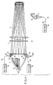
- FIG. 1 is a schematic view showing the entire configuration of the optical system of a projection type display apparatus using a lighting device according to a first embodiment of the present invention.
- FIG. 2 is a schematic view showing principal parts of the optical system of the projection type display apparatus.
- FIG. 3 is a block diagram showing the circuit configuration of the projection type display apparatus.
- a portion (a) in FIG. 2 is a view showing principal parts of the lighting device.
- a portion (b) in FIG. 2 is a front view showing a dividing/overlapping lens, and a portion (c) in FIG. 2 is a sectional view showing the same.
- a portion (d) in FIG. 2 is a sectional view showing a lens prism.
- the projection type display apparatus using the lighting device has a discharge bulb 11 comprising an arbitrary-shaped reflecting mirror 9 and an emitting section 10.
- the arbitrary-shaped reflecting mirror 9 reflects light emitted from the emitting section 10 of the discharge bulb 11 so that the emitted light can be formed into a parallel beam. Short and long wavelength unnecessary lights are absorbed/reflected by a UV filter (not shown) and an IR filter (not shown), and thereafter, removed respectively.
- a come-off portion 12 on the optical axis is generated in the discharge bulb 11 from the following structural reasons, that is, the structure of lamp main body and emitting electrode, reflecting mirror for fixing those, etc.
- a light source 13 is provided in order to overlap the illuminating light of the semiconductor light-emitting element such as laser beam source using the come-off portion 12.
- the light source 13 comprises a semiconductor light emitting element such as light emitting diode or laser beam source.
- a center lens 15 of dividing/overlapping lens, that is, a multi-lens 16 is arranged near the optical axis of the come-off portion of the discharge bulb 11.
- a lens prism 20 is further arranged on the light source side.
- the lens prism 20 includes a lens and a mirror 19.
- NA numerical aperture
- ⁇ maximum effective angle
- n refractive index
- NA n sin ⁇
- the lens prism 20 is arranged coaxially with the come-off portion 12.
- F value effective angle (brightness) index
- F no 1/(2NA)
- a plane holder 18 having high reflectivity is provided at the boundary between fly-eyes. By doing so, it is possible to obtain necessary intensity with the minimum optical loss. This is based on the following reason. That is, the plane holder 18 has a very small occupied area in the optical axis direction, and further, is provided at the boundary between array lenses of the fly-eye irradiating the periphery of the panel.
- the plane holder 18 has a thickness in the optical axis direction. Further, the plane holder 18 is subjected to high reflecting surface treatment, and is arranged approximately parallel with the optical axis. By doing so, even if oblique light is incident on the plane holder 18, as shown in a portion (c) in FIG. 2, in the light reflected by the plane holder 18, light within the NA of the multi-lens 16 is optical axis object. However, the coupled optic-axial, angle same as pre-reflection is kept; therefore, no optical loss is newly generated. This is because light other than the multi-lens NA naturally becomes stray light.
- the emitted light of the discharge bulb 11 is divided by the multi-lenses 16 and 17, and overlapped and averaged by a condenser lens 21. By doing so, the emitted light is irradiated to transmission type light valves 27, 28 and 29 at approximately uniform quality.
- a dichroic mirror 22 is a color separation filter, and reflects an R light (red light) while transmitting GB light (green and blue light).
- a dichroic mirror 24 reflects the G light (green light) while transmitting the B light (blue light).
- the R and G lights separated by the dichroic mirrors 22 and 24 are incident on light valves 27 and 28, respectively, while the B light is incident on the light valve 29 via reflecting mirrors 25 and 26.
- the color light valves 27 to 29 enable color display.
- Light valve transmitted light thus obtained is synthesized by a complex prism 30, and projected by a projection lens 31, and thereby, a video image is displayed on the screen (not shown) in accordance with given video information.
- a PBS Polarizing Beam Splitter
- a polarizing axis rotary plate both not shown
- the light valves 27 to 29 may be used as the light valves 27 to 29 in place of using polarization of liquid crystal and the like.
- the reflecting mirror 9 of the discharge bulb 11 is an elliptic mirror
- a rod lens is used in place of the fly-eye lens. By doing so, it is possible to build up a lighting optical system having high efficiency and quality with respect to a micro light valve of about 1-inch.
- the projection type display apparatus includes a power circuit 41, a microcomputer 46, a lamp drive circuit 43, a video signal processing circuit 44, and a liquid crystal drive circuit 45.
- the microcomputer 46 functions as a control circuit for controlling the entire operation of the above circuits.
- the video signal processing circuit 44 is supplied with a video signal from a signal source 51.
- the liquid crystal drive circuit 45 drives the transmission type light valves 27 to 29 such as liquid crystal panel.
- the power circuit 41 converts an AC (alternating current) voltage from a commercial AC source into a DC (direct current) voltage so as to supply a predetermined DC voltage (+B) to each of the above circuits. (In this case, the DC voltage value supplied to each circuit is simplified in FIG. 3 although it is different.)
- the lamp drive circuit 43 lights and drives the discharge bulb 11 used as light source.
- the light from the discharge bulb 11 is irradiated to the transmission type light valves 27 to 29 such as liquid crystal panel.
- the feature of the present invention that is, the light source 13 comprising semiconductor light emitting element and the optical fiber 14 used for there are provided close to each other.
- the transmittance of the liquid crystal panels 27 to 29 changes in accordance with the given video signal, and light irradiated to the liquid crystal panels 27 to 29 is emitted after being emitted.
- the emitted video light is projected on a screen (not shown) by the projection lens 31 so that an enlarged video image can be displayed on the screen.
- an optical box 50 includes a separating function of separating the light from the discharge bulb 11 into R, G and B lights.
- the video signal processing circuit 44 converts the video signal supplied from the signal source 51 into RGB signals so that the RGB signals can be supplied to the above liquid crystal panels.
- the microcomputer 46 controls the power circuit 41, lamp drive circuit 43, and video signal processing circuit 44. In this case, the microcomputer 46 controls power on/off and each operation of the circuits 43 and 44 in accordance with the instruction from a remote controller (not shown) by user's operation.
- the projection type display apparatus overlaps the illuminating light from the semiconductor light emitting element such as laser light source is overlapped using the optical axis area having no effective light in nature.
- the projection type display apparatus can improve color rendering, which has not been sufficiently obtained using only discharge bulb.
- the above semiconductor light-emitting element is not necessarily laser beam source, and light source comprising other semiconductor light emitting elements such as light emitting diode may be used. In this case, the same operation and effect can be obtained. For example, if the light emitting diode is used, directivity is secured by optical fiber, and thereby, sufficient luminance overlapping is performed, so that color rendering can be improved.
- the second embodiment provides a lighting device having a plurality of light sources and a projection type display apparatus using the same. Illuminating light from semiconductor light emitting element such as laser beam source is overlapped at the outermost peripheral portion of the discharge bulb.
- FIG. 4 is a schematic view showing the optical system of a projection type display apparatus using a lighting device according to a second embodiment of the present invention.
- FIG. 5 is a schematic view showing a kaleidoscope used in the embodiments of the lighting device of the present invention.
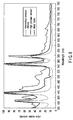
- FIG. 6 is a graph to explain a second embodiment of the present invention, and shows the available state of each spectrum of a discharge tube light source of the present invention and general optical primaries.
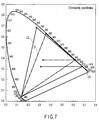
- FIG. 7 is a chromaticity diagram showing color rendering of the light source according to the present invention.
- the second embodiment is preferable particularly to the case where liquid crystal having a margin in illumination F-number is used as the light valve without using micro lenses.
- the illuminating light from the semiconductor light-emitting element is overlapped at the outermost peripheral portion of the multi-lens where optical available efficiency loss is little.
- irradiated light from a light source 61 comprising the semiconductor light emitting element such as laser beam source is guided to an optical overlapping multi-lens 16 arranged near the discharge bulb 11 via optical fiber 63.
- Emitted light 65 is overlapped with irradiated light within the NA of the multi-lens 16 via a mirror plane 69 of a reflecting prism 67 substantially same as the reflecting prism 20 described in FIG. 2.
- the irradiated light is irradiated from the light source 61 comprising the semiconductor light-emitting element such as laser beam source, which is a second lighting source parallel with the optical axis.
- irradiated light from a light source 62 comprising the semiconductor light emitting element is overlapped within the NA of the multi-lens 16 via a mirror plane 70 of a reflecting prism 68 arranged at the opposite side.
- the decentration of principal ray shown by a broken line H of FIG. 4 is generated in accordance with the wavelength of overlapping light.
- the light sources 61 and 62 comprising the same semiconductor light-emitting element are prepared, and arranged so that they can be positioned symmetrically with respect to the optical axis.
- Optical overlapping by the multi-lens is dividing/overlapping by each multi-lens. For this reason, if the semiconductor overlapping light illuminated to one multi-lens array to be overlapped is un-uniform, the following problem arises. That is, the overlapping light intactly becomes uneven in illumination or color; as a result, the projected image also becomes un-uniform.
- a kaleidoscope may be arranged at each emitting portion of the optical fibers 63 and 64.
- FIG. 4 shows the example in which a kaleidoscope 66 is arranged at the emitting portion of the optical fibers 64.
- a diffuser 66-2 converts light guided from the light source 62 comprising semiconductor light emitting element via the optical fiber 64 into diffused light.
- the above kaleidoscope 66 converts the diffused light into uniform and high quality overlapping light (source) within the multi-lens NA range. By doing so, it is possible to provide a projection type display apparatus including further desirable lighting device.
- FIG. 5 shows the basic principle of the kaleidoscope 66.
- the structure of the kaleidoscope 66 has been already disclosed in Jpn. Pat. Appln. KOKAI Publication No. 2000-259541 filed by the present applicant; therefore, the details are omitted.
- the outline of the structure is as shown in FIG. 5.
- the kaleidoscope 66 comprises a pyramid-shaped main body 66-1, a diffuse-reflecting plane 66-2, and an irradiating plane 66-3, as seen from FIG. 5.
- the pyramid-shaped main body 66-1 has a mirror-finished inner plane.
- the diffuse-reflecting plane 66-2 is provided at the small-diametrical end portion of the main body 66-1, and the irradiating plane 66-3 is provided at the large-diametrical end portion thereof.
- the light from the optical fiber 64 is irradiated to the diffuse-reflecting plane 66-2. Thereafter, light diffused and reflected by the diffuse-reflecting plane 66-2 is reflected on the inner plane of the main body 66-1 so that light can be emitted from the irradiating plane 66-3.
- a lens 73 is provided in order to convert the emitted light into a parallel light.
- the third embodiment specifies the optimal wavelength as the light source of the lighting device used for the projection type display apparatus when using laser light source as the semiconductor light-emitting element.
- FIG. 6 is a graph showing the available state of each spectrum of discharge tube light source and general optical primaries in order to explain a third embodiment of the present invention.
- FIG. 7 is a chromaticity diagram showing color rendering of the light source according to the present invention.
- laser beam source As the semiconductor light-emitting element, it is not necessarily required to use laser beam source as the semiconductor light-emitting element, and a light emitting diode may be used.
- the semiconductor light-emitting element is limited to the laser beam source, arbitrary wavelength is selectable. For this reason, it is possible to overlap any one monochromatic light of R, G and B lights, for example. In such a case, it is desirable to use a laser beam source having a specific wavelength in order to. The following is a description on the specific wavelength for obtaining the optimal color rendering.
- the graph of FIG. 6 shows the available state of each spectrum of discharge tube light source and general optical primaries, taking the abscissa as wavelength.
- a locus C1 shown in FIG. 7 is obtained.
- the outer peripheral surrounded range of the chromaticity diagram is a visual region as color, and numerical values denote wavelength (nm).
- wavelength nm
- red critical (criticality) 780 nm
- violet critical 380 nm
- a curved line crossing the central portion of the diagram is a black body locus called "white”, and expressed numerical values denote color temperature (K).
- the following matter can be understood when effectively applying discharge tube spectrum generated from single discharge bulb 11 and removing unnecessary light to the projection type display apparatus. That is, it is inevitably required to take yellow to orange color components close to the wavelength from 560 to 580 nm having a wide range as discharge tube spectrum. In other words, as seen from the locus C1 of FIG. 7, red has an orange narrow color rendering range; on the other hand, green has a yellowish-green narrow color rendering range. Therefore, it can be seen that a projection light has very low color rendering. Simultaneously, the projection light has the following problem. That is, the NW chromaticity coordinates has low color temperature, and is biased toward green.
- the green light valve must carry out light limitation of twenty percents or more even in the white drive stage. Therefore, the contrast ability (dynamic range) as optical light valve deteriorates about twenty percents; as a result, the projection light has low color rendering, contrast and quality.
- Irradiation light from laser beam source is overlapped with the irradiation light (locus C1) generated by the discharge bulb 11. That is, the preceding irradiation light (locus C1) is overlapped with a 635-nm laser beam shown by a locus C3 in the diagram of FIG. 7.
- the laser beam is equivalent to green-blue light 60% ND, and has 70% power of the red light of the irradiation light from the single discharge bulb. By doing so, the color rendering of the above irradiation light changes from the locus C1 to a locus C2. It can be seen that the above change serves to restore luminance and improves red monochromatic purity.
- the overlapping red light source has preferable red chromatic purity so long as it becomes long wavelength.
- both luminosity factor (visual sensibility) and transmittance of each optical element are simultaneously reduced; for this reason, a large number of power must be inputted.
- NW improvement is made; however, red chromatic purity is not so improved.
- the overlapping light wavelength should be selected taking the price and light emission efficiency of the LD source into consideration.
- the laser beam source which is red light source, has a wavelength of 600 nm or more.
- the green light source that is, the laser beam source has a wavelength from 500 to 535 nm so that the green coordinate can be close to N green coordinate.
- laser beam source which is blue light source suitable for being overlapped with the above light sources, has a wavelength from 440 to 490 nm.
- the light source having the above wavelengths is simultaneously overlapped, and thereby, it is possible to provide a projection type display apparatus capable of displaying higher quality video image.
- the light-emitting element used for the present invention is easy to directly obtain a desired light with respect to red light. However, it is difficult to obtain optical elements for resonating and emitting green or blue light. Further, the optical element is expensive, and it is difficult to provide the optical element as actual product capable of maintaining emission environment such as temperature control.
- an up-conversion laser light source apparatus capable of obtaining short-wavelength oscillation light in two stages.
- limitation is made in order to secure safety within human body reaction period (time until human closes his eyelids or turns his eyes from light).
- the projection type display apparatus is a front projection type
- the present invention is applicable within a range that the laser beam power of the semiconductor light source satisfies class-2 laser safety standard.
- the projection type display apparatus is a rear projection type display apparatus always used for appreciation, the present invention is applicable within a range that the laser beam power of the semiconductor light source satisfies class-1 laser safety standard.
- the semiconductor light source has considerably long lifetime of about several million hours as compared with the lifetime (1000 to 8000 hours) of the discharge bulb. For this reason, there is almost no possibility that two light sources simultaneously are broken down by coming the lifetime.
- the diagnosis is given by light source drive signal monitor means, and thereafter, error message can be displayed using the remaining light source. This is a function convenient for users.
- the lamp drive circuit 43 of FIG. 3 detects the change of driving current, and thereby, lamp breakdown is detected.
- the video signal processing circuit 44 generates an image signal representing the error message.
- the liquid crystal drive circuit 45 drives the liquid crystal panels 27 to 29, the projection light corresponding to the image signal is projected so that the error message can be displayed on the screen (not shown).
- the breakdown of the discharge bulb 11 may be displayed using the semiconductor light source 13, or the breakdown of the semiconductor light source 13 may be displayed using the irradiation light of the discharge bulb 11.
- the fourth embodiment describes a projection type display apparatus using a DMD (Digital Micro Mirror Device) system as a space modulation light valve.
- FIG. 9 is a schematic view showing the optical system of the projection type display apparatus using the DMD of the fourth embodiment.
- FIG. 10 is a timing chart to explain the operation of the fourth embodiment.
- DMD Digital Micro Mirror Device
- irradiation light from the discharge bulb 11 is irradiated to a color wheel 86 via a kaleidoscope 85.
- the color wheel 86 is rotated at 60 frames per second.
- the irradiation light passed through the color wheel 86 passes through a condenser lens 87 and relay lenses 88 and 89, and projected onto a DMD chip 90.
- the DMD chip 90 is a very small mirror element assembly, and includes a micro-mirror array. Each mirror element is supported by hinge structure, and the micro-mirror is movable around the hinge. As illustrated in a portion (d) in FIG. 9, the DMD chip 90 is tilted to an on state (solid line) or off state (broken line).
- the on state light incident on the mirror is reflected to a projection lens 91; on the other hand, in the off state, the light is reflected to the direction different from the projection lens 91. Namely, it is possible to modulate light incident on the surface of the mirror depending upon the on or off state of the mirror tilt angle.
- Reflecting light from the mirror passes through the projection lens 91 so that image can be displayed on the screen. If the mirror is in an on state for a long time, the video image on the screen becomes bright; on the other hand, in the off state, it becomes dark. Therefore, the on/off of the mirror is controlled in accordance with the video signal level, and thereby, the video image can be displayed on the screen.
- the color wheel 86 is divided into R. G and B sectors, as seen from a portion (b) in FIG. 9 and a portion (c) in FIG. 9.
- the color wheel 86 is rotated at a predetermined rotational speed, and thereby, R, G and B lights are successively irradiated to the DMD.
- the DMD is driven at irradiation timing in accordance with R, G and B video signals so that color display can be achieved.
- one optical system is divided into R, G and B in time division, so that color display can be achieved by the small-scale optical system.
- light sources 81 and 83 comprising semiconductor light-emitting element are arranged with respect to the projection type display apparatus using the above DMD system, together with optical fibers 82 and 84. Irradiation light from the optical fibers 82 and 84 is irradiated to the kaleidoscope 85.
- FIG. 10 shows emission timing of the light sources 81 and 83 comprising semiconductor light-emitting element and drive timing of the DMD 90.
- One example is the timing T1 case where the light sources 81 and 83 comprising semiconductor light-emitting element continue to emit light.
- the DMD 90 alternately changes at the timing T2 equally divided into R, G and B.
- the color wheel 86 has equally divided three regions shown in a portion (b) in FIG. 9.
- the timing T4 case where the light sources 81 and 83 comprising semiconductor light-emitting element emits light in synchronous with the operation timing of the corresponding color light source of three primaries of the DMD 90.
- the light sources 81 and 83 comprising semiconductor light-emitting element are red light source, and is synchronized with the R timing T5 of the DMD.
- the color wheel 86 has narrow R region shown in a portion (c) in FIG. 9, as described above.
- the emission of the light sources 81 and 83 comprising semiconductor light-emitting element may be synchronized with the specific color of the color wheel 86 at the timing T2 equally divided into three.
- overlapping of the light source comprising semiconductor light-emitting element is applied to the projection type display apparatus using the DMD system.
- the emission timing of the light source comprising semiconductor light-emitting element is synchronized with the operation of the color wheel.
- the irradiation light by the semiconductor light-emitting element such as semiconductor laser is overlapped with the illuminating light from the discharge bulb.
- the irradiation light is overlapped with the illuminating light, using the portion near the optical axis of the discharge bulb and the outermost peripheral portion naturally having little effective light. Therefore, red component, which has not been sufficiently obtained using the emission of discharge bulb, is replenished. By doing so, it is possible to provide a projection type display apparatus, which can obtain projection light having high luminance, color rendering and contrast.
Landscapes
- Engineering & Computer Science (AREA)
- Multimedia (AREA)
- Signal Processing (AREA)
- Projection Apparatus (AREA)
- Liquid Crystal (AREA)
- Non-Portable Lighting Devices Or Systems Thereof (AREA)
Abstract
A light device has a plurality of light sources,
and laser beam sources (13, 14) are arranged near
a discharge bulb (11) so that the laser beam can be
overlapped with illuminating light from the discharge
bulb. By doing so, the illuminating light is
irradiated as overlapped illuminating light reinforcing
red component, so that color rendering and luminance
can be improved.
Description
The present invention relates to a lighting
device. In particular, the present invention relates
to a lighting device using semiconductor light-emitting
element such as laser beam source, and to a projection
type display apparatus using the lighting device.
Recently, the projection (projector) type display
apparatus has come into wide use. However, with the
development of high image quality resulting from high-vision,
high-level color rendering is required as the
image display apparatus. Short arc type discharge
lamps such as mercury lamp, metal halide lamp and xenon
lamp are mainly used as the light source for the
projection type display apparatus.
In the above discharge lamps, a reflecting mirror
guides an optical path, and unnecessary light is
removed using individual filters. A fly-eye lens
divides irradiating light, and overlaps and averages
it together with a condenser lens, and thereby,
the discharge lamp irradiates a light valve with
approximately uniform quality. Thereafter, the
irradiating light guided by a dichroic mirror is
transmitted by the light valve, and synthesized as
projection light by complex prism so that image can
be displayed on a screen.
However, the above-mentioned light source is
a continuous spectrum light source having the steep
peak. For this reason, in many projection type display
devices, it is difficult to provide color rendering,
that is, monochromatic purity of RGB and the total
luminance flux after optical synthesis together.
In order to give priority to color rendering, only
slight region equivalent to RGB wavelength in the
emission spectrum of the discharge lamp must be used
as effective light. As a result, the total output
luminance flux after synthesis becomes small. On the
other hand, in order to give priority to output
luminance flux value, RGB selection light must be
expanded to the maximum range having no intersection.
As a result, not only the chromatic purity of each
color deteriorates, but also chromatic phenomenon is
confirmed in white uniformity after synthesis;
therefore, color rendering is lost. The removed
unnecessary light has the possibility of causing the
problem as heating or stray light.
The above problem results from the discharge lamp
having continuous and steep spectrum distribution.
A projection type display device using semiconductor
light sources such as light emitting diode and laser
diode has been developed as a new source for solving
the above problem. For example, Jpn. Pat. Appln. KOKAI
Publication No. 2000-305040 discloses the following
technique. That is, a light emitting diode is arranged
before a complex prism of the projection type display
apparatus so that color rendering and white balance can
be improved. By doing so, red color component, which
has not been sufficiently obtained by only discharge
lamp, is replenished, so that color rendering can be
improved.
However, in general, light is easy to be diffused
in the light emitting diode. For this reason, the
conventional lighting device has the following problem
that luminance and efficiency are not sufficiently
improved in the projection light, which is the final
output.
Accordingly, it is an embodiment of the present
invention to provide a lighting device, which can
improve color rendering and luminance insufficient by
only discharge bulb source, using a semiconductor
light-emitting element such as laser beam source.
Another embodiment of the present invention is to
provide a projection type display apparatus using the
lighting device.
According to an aspect of the present invention,
there is provided a lighting device having a plurality
of light sources, comprises first means for generating
first illuminating light using a discharge bulb; second
means, arranged near the first means, for generating
second illuminating light using laser beam; and means
for overlapping the first illuminating light with the
second illuminating light, and emitting the overlapping
light.
As described above, the laser beam source having
sufficient output and directivity is used as light
source overlapping with the discharge bulb. By doing
so, red component, which has not been sufficiently
obtained by only output of the discharge bulb, is
replenished; therefore, it is possible to provide
a lighting device capable of improving color rendering
and luminance.
According to an aspect of the present invention,
there is provided a projection type display apparatus,
having a light valve receiving an illuminating light
from a light source and modulating an emitting light in
accordance with a video signal, and projecting a video
image light emitted from the light valve, comprises,
an illuminating light source overlapping a first
illuminating light from the discharge bulb with
a second illuminating light from a laser light source
arranged near the discharge bulb by means, and emitting
the overlapped light; a light valve receiving light
irradiated from the illuminating light, and emitting
incident light so as to transmit or reflect it; a drive
circuit diving the light valve in accordance with
a video signal; and a projection lens projecting
a video light emitted from the light valve.
According to an aspect of the present invention,
there is provided a projection type display apparatus,
having a light valve receiving an illuminating light
from a light source and modulating an emitting light in
accordance with a video signal, and projecting a video
image light emitted from the light valve, comprises
an illuminating light source overlapping a first
illuminating light from the discharge bulb with
a second illuminating light from a laser light source
arranged near the discharge bulb by means, and emitting
the overlapped light; a light valve receiving light
irradiated from the illuminating light; a detection
circuit detecting failure when one of the discharge
bulb or laser beam source fails; a signal generating
circuit generating a message signal in response to the
detection result by the detection circuit; a drive
circuit diving the light valve in accordance with
a video signal and the message signal; and a projection
lens projecting a video light emitted from the light
valve.
Therefore, it is possible to provide a projection
type display apparatus, which can irradiate a
projection light having high color rendering and good
balance.
This summary of the invention does not necessarily
describe all necessary features so that the invention
may also be a sub-combination of these described
features.
The invention can be more fully understood from
the following detailed description when taken in
conjunction with the accompanying drawings, in which:
A lighting device according to the embodiments of
the present invention and a projection type display
apparatus using the same will be described below with
reference to the accompanying drawings.
The first embodiment provides a lighting device
having a plurality of light sources and a projection
type display apparatus using the lighting device. The
lighting device overlaps light from the semiconductor
light-emitting element such as laser beam source to the
come-off portion on the optical axis of the discharge
bulb. FIG. 1 is a schematic view showing the entire
configuration of the optical system of a projection
type display apparatus using a lighting device
according to a first embodiment of the present
invention. FIG. 2 is a schematic view showing
principal parts of the optical system of the projection
type display apparatus. FIG. 3 is a block diagram
showing the circuit configuration of the projection
type display apparatus.
The projection type display apparatus using the
lighting device will be described below with reference
to FIG. 1 and FIG. 2. Here, a portion (a) in FIG. 2 is
a view showing principal parts of the lighting device.
A portion (b) in FIG. 2 is a front view showing a
dividing/overlapping lens, and a portion (c) in FIG. 2
is a sectional view showing the same. A portion (d) in
FIG. 2 is a sectional view showing a lens prism.
The projection type display apparatus using the
lighting device has a discharge bulb 11 comprising
an arbitrary-shaped reflecting mirror 9 and an emitting
section 10. The arbitrary-shaped reflecting mirror 9
reflects light emitted from the emitting section 10 of
the discharge bulb 11 so that the emitted light can be
formed into a parallel beam. Short and long wavelength
unnecessary lights are absorbed/reflected by a UV
filter (not shown) and an IR filter (not shown), and
thereafter, removed respectively.
As shown in FIG. 1, a come-off portion 12 on
the optical axis is generated in the discharge bulb 11
from the following structural reasons, that is, the
structure of lamp main body and emitting electrode,
reflecting mirror for fixing those, etc. In the first
embodiment, a light source 13 is provided in order to
overlap the illuminating light of the semiconductor
light-emitting element such as laser beam source using
the come-off portion 12. The light source 13 comprises
a semiconductor light emitting element such as light
emitting diode or laser beam source. A center lens 15
of dividing/overlapping lens, that is, a multi-lens 16
is arranged near the optical axis of the come-off
portion of the discharge bulb 11. As illustrated in
FIG. 2, a lens prism 20 is further arranged on the
light source side. The lens prism 20 includes a lens
and a mirror 19. The lens is used for transmitting
light emitted from the light source 13 such as laser
beam source via an optical fiver 14 so as to satisfy
the NA of the multi-lens 16 (NA: numerical aperture, :
maximum effective angle, n: refractive index; in this
case, NA = n sin ). The mirror 19 reflects light
reached the optical axis from the periphery to the
projection direction.
As described above, in order to overlap the light
from the light source 13 comprising the semiconductor
light emitting element with the come-off portion 12 via
the optical fiber 14, the lens prism 20 is arranged
coaxially with the come-off portion 12. By doing so,
it is possible to improve color rendering without
deteriorating F-number of the lighting system (F value:
effective angle (brightness) index, F no = 1/(2NA)).
Namely, in the structure of the discharge bulb 11,
effective light is very few in the come-off portion 12.
For this reason, even if optical overlapping is carried
out using the come-off portion, the reduction of
optical available efficiency can be kept to the
minimum. Therefore, it is possible to build up
a projection type display apparatus having a very
effective hybrid light source comprising the discharge
bulb and the semiconductor light emitting element.
In order to hold the reflecting prism lens 20 used
for synthesis to the multi-lens 16, a plane holder 18
having high reflectivity is provided at the boundary
between fly-eyes. By doing so, it is possible to
obtain necessary intensity with the minimum optical
loss. This is based on the following reason. That is,
the plane holder 18 has a very small occupied area in
the optical axis direction, and further, is provided
at the boundary between array lenses of the fly-eye
irradiating the periphery of the panel.
More specifically, the plane holder 18 has
a thickness in the optical axis direction. Further,
the plane holder 18 is subjected to high reflecting
surface treatment, and is arranged approximately
parallel with the optical axis. By doing so, even
if oblique light is incident on the plane holder 18,
as shown in a portion (c) in FIG. 2, in the light
reflected by the plane holder 18, light within the NA
of the multi-lens 16 is optical axis object. However,
the coupled optic-axial, angle same as pre-reflection is
kept; therefore, no optical loss is newly generated.
This is because light other than the multi-lens NA
naturally becomes stray light.
The emitted light of the discharge bulb 11 is
divided by the multi-lenses 16 and 17, and overlapped
and averaged by a condenser lens 21. By doing so, the
emitted light is irradiated to transmission type light
valves 27, 28 and 29 at approximately uniform quality.
A dichroic mirror 22 is a color separation filter,
and reflects an R light (red light) while transmitting
GB light (green and blue light). On the other hand,
a dichroic mirror 24 reflects the G light (green light)
while transmitting the B light (blue light). The R and
G lights separated by the dichroic mirrors 22 and 24
are incident on light valves 27 and 28, respectively,
while the B light is incident on the light valve 29 via
reflecting mirrors 25 and 26. The color light valves
27 to 29 enable color display. Light valve transmitted
light thus obtained is synthesized by a complex prism
30, and projected by a projection lens 31, and thereby,
a video image is displayed on the screen (not shown) in
accordance with given video information.
A PBS (Polarizing Beam Splitter) and a polarizing
axis rotary plate (both not shown) may be used as the
light valves 27 to 29 in place of using polarization of
liquid crystal and the like. If the reflecting mirror
9 of the discharge bulb 11 is an elliptic mirror, a rod
lens is used in place of the fly-eye lens. By doing
so, it is possible to build up a lighting optical
system having high efficiency and quality with respect
to a micro light valve of about 1-inch.
The electric circuit system of the projection
type display apparatus of the present invention will
be described in detail with reference to FIG. 3.
As seen from FIG. 3, the projection type display
apparatus includes a power circuit 41, a microcomputer
46, a lamp drive circuit 43, a video signal processing
circuit 44, and a liquid crystal drive circuit 45.
The microcomputer 46 functions as a control circuit for
controlling the entire operation of the above circuits.
The video signal processing circuit 44 is supplied with
a video signal from a signal source 51. The liquid
crystal drive circuit 45 drives the transmission type
light valves 27 to 29 such as liquid crystal panel.
The power circuit 41 converts an AC (alternating
current) voltage from a commercial AC source into a DC
(direct current) voltage so as to supply a predetermined
DC voltage (+B) to each of the above circuits.
(In this case, the DC voltage value supplied to each
circuit is simplified in FIG. 3 although it is
different.)
The lamp drive circuit 43 lights and drives the
discharge bulb 11 used as light source. The light from
the discharge bulb 11 is irradiated to the transmission
type light valves 27 to 29 such as liquid crystal
panel. The feature of the present invention, that is,
the light source 13 comprising semiconductor light
emitting element and the optical fiber 14 used for
there are provided close to each other. The
transmittance of the liquid crystal panels 27 to 29
changes in accordance with the given video signal,
and light irradiated to the liquid crystal panels 27 to
29 is emitted after being emitted. The emitted video
light is projected on a screen (not shown) by the
projection lens 31 so that an enlarged video image can
be displayed on the screen.
If the projection type display apparatus is
a three-panels type, three liquid crystal panels for
R (red), G (green) and B (blue) are used. Then, the
light from the discharge bulb 11 is separated into R, G
and B lights so that the R, G and B lights can be
irradiated to the three liquid crystal panels 27 to 29,
respectively. Further, light transmitted through each
of the liquid crystal panels 27 to 29 is synthesized,
and thereafter, irradiated to the projection lens 31.
In FIG. 3, the above-mentioned structure is simplified.
Therefore, an optical box 50 includes a separating
function of separating the light from the discharge
bulb 11 into R, G and B lights.
The video signal processing circuit 44 converts
the video signal supplied from the signal source 51
into RGB signals so that the RGB signals can be
supplied to the above liquid crystal panels. The
microcomputer 46 controls the power circuit 41, lamp
drive circuit 43, and video signal processing circuit
44. In this case, the microcomputer 46 controls power
on/off and each operation of the circuits 43 and 44
in accordance with the instruction from a remote
controller (not shown) by user's operation.
As is evident from the above description,
according to the first embodiment of the present
invention, it is possible to provide a projection type
display apparatus having high luminance and high
contrast. That is, the projection type display
apparatus overlaps the illuminating light from the
semiconductor light emitting element such as laser
light source is overlapped using the optical axis area
having no effective light in nature. By doing so, the
projection type display apparatus can improve color
rendering, which has not been sufficiently obtained
using only discharge bulb.
The above semiconductor light-emitting element is
not necessarily laser beam source, and light source
comprising other semiconductor light emitting elements
such as light emitting diode may be used. In this
case, the same operation and effect can be obtained.
For example, if the light emitting diode is used,
directivity is secured by optical fiber, and thereby,
sufficient luminance overlapping is performed, so that
color rendering can be improved.
The second embodiment provides a lighting device
having a plurality of light sources and a projection
type display apparatus using the same. Illuminating
light from semiconductor light emitting element such
as laser beam source is overlapped at the outermost
peripheral portion of the discharge bulb. FIG. 4 is
a schematic view showing the optical system of
a projection type display apparatus using a lighting
device according to a second embodiment of the
present invention. FIG. 5 is a schematic view showing
a kaleidoscope used in the embodiments of the lighting
device of the present invention. FIG. 6 is a graph to
explain a second embodiment of the present invention,
and shows the available state of each spectrum of
a discharge tube light source of the present invention
and general optical primaries. FIG. 7 is a chromaticity
diagram showing color rendering of the light
source according to the present invention.
The second embodiment is preferable particularly
to the case where liquid crystal having a margin in
illumination F-number is used as the light valve
without using micro lenses. As seen from FIG. 4,
the illuminating light from the semiconductor light-emitting
element is overlapped at the outermost
peripheral portion of the multi-lens where optical
available efficiency loss is little.
In FIG. 4, irradiated light from a light source 61
comprising the semiconductor light emitting element
such as laser beam source is guided to an optical
overlapping multi-lens 16 arranged near the discharge
bulb 11 via optical fiber 63. Emitted light 65 is
overlapped with irradiated light within the NA of the
multi-lens 16 via a mirror plane 69 of a reflecting
prism 67 substantially same as the reflecting prism
20 described in FIG. 2. The irradiated light is
irradiated from the light source 61 comprising the
semiconductor light-emitting element such as laser
beam source, which is a second lighting source parallel
with the optical axis. Likewise, irradiated light from
a light source 62 comprising the semiconductor light
emitting element is overlapped within the NA of the
multi-lens 16 via a mirror plane 70 of a reflecting
prism 68 arranged at the opposite side.
According to the second embodiment, the
decentration of principal ray shown by a broken line
H of FIG. 4 is generated in accordance with the
wavelength of overlapping light. For this reason,
in the optical system using the liquid crystal light
valve, which is easy to receive the influence of the
angle of field, contrast deterioration readily occurs.
Thus, as depicted in FIG. 4, the light sources 61 and
62 comprising the same semiconductor light-emitting
element are prepared, and arranged so that they can be
positioned symmetrically with respect to the optical
axis. By doing so, it is possible to solve the above
problem.
In the second embodiment, even if the overlapping
device is enlarged in the direction reverse to the
optical axis, optical available efficiency does not
deteriorate. Therefore, so long as there exists
allowable space, a condenser lens 71 shown in a portion
of (b) in FIG. 4 and a discrete reflecting mirror 72
are arranged in place of the expensive prism having
a complicate shape, and thereby, the same effect can be
obtained.
Optical overlapping by the multi-lens is dividing/overlapping by each multi-lens. For this reason, if
the semiconductor overlapping light illuminated to one
multi-lens array to be overlapped is un-uniform, the
following problem arises. That is, the overlapping
light intactly becomes uneven in illumination or color;
as a result, the projected image also becomes
un-uniform.
In order to solve the above problem, a
kaleidoscope may be arranged at each emitting portion
of the optical fibers 63 and 64. In FIG. 4 shows the
example in which a kaleidoscope 66 is arranged at the
emitting portion of the optical fibers 64. A diffuser
66-2 converts light guided from the light source 62
comprising semiconductor light emitting element via the
optical fiber 64 into diffused light. Then, the above
kaleidoscope 66 converts the diffused light into
uniform and high quality overlapping light (source)
within the multi-lens NA range. By doing so, it is
possible to provide a projection type display apparatus
including further desirable lighting device.
FIG. 5 shows the basic principle of the
kaleidoscope 66. The structure of the kaleidoscope 66
has been already disclosed in Jpn. Pat. Appln. KOKAI
Publication No. 2000-259541 filed by the present
applicant; therefore, the details are omitted.
The outline of the structure is as shown in FIG. 5.
More specifically, the kaleidoscope 66 comprises
a pyramid-shaped main body 66-1, a diffuse-reflecting
plane 66-2, and an irradiating plane 66-3, as seen
from FIG. 5. The pyramid-shaped main body 66-1 has
a mirror-finished inner plane. The diffuse-reflecting
plane 66-2 is provided at the small-diametrical end
portion of the main body 66-1, and the irradiating
plane 66-3 is provided at the large-diametrical end
portion thereof.
The light from the optical fiber 64 is irradiated
to the diffuse-reflecting plane 66-2. Thereafter,
light diffused and reflected by the diffuse-reflecting
plane 66-2 is reflected on the inner plane of the main
body 66-1 so that light can be emitted from the
irradiating plane 66-3. In this case, a lens 73 is
provided in order to convert the emitted light into
a parallel light.
The third embodiment specifies the optimal
wavelength as the light source of the lighting device
used for the projection type display apparatus when
using laser light source as the semiconductor light-emitting
element. FIG. 6 is a graph showing the
available state of each spectrum of discharge tube
light source and general optical primaries in order
to explain a third embodiment of the present invention.
FIG. 7 is a chromaticity diagram showing color
rendering of the light source according to the present
invention.
In the description of the above embodiments, it is
not necessarily required to use laser beam source
as the semiconductor light-emitting element, and
a light emitting diode may be used. However, if the
semiconductor light-emitting element is limited to the
laser beam source, arbitrary wavelength is selectable.
For this reason, it is possible to overlap any one
monochromatic light of R, G and B lights, for example.
In such a case, it is desirable to use a laser beam
source having a specific wavelength in order to.
The following is a description on the specific
wavelength for obtaining the optimal color rendering.
The graph of FIG. 6 shows the available state of
each spectrum of discharge tube light source and
general optical primaries, taking the abscissa as
wavelength. When representing color rending of the
above state by a chromaticity diagram, a locus C1 shown
in FIG. 7 is obtained.
Giving supplementary explanation to FIG. 7, the
outer peripheral surrounded range of the chromaticity
diagram is a visual region as color, and numerical
values denote wavelength (nm). In the chromaticity
diagram, there exist red critical (criticality)
(780 nm) at the right side, and when the wavelength
gradually becomes short, red (~ 600 nm), orange,
yellow, yellowish green, green (510 ~540 nm), and
cyan, blue (450 ~ 480 nm) are plotted. There exist
violet critical (380 nm) at the left lower side. A
curved line crossing the central portion of the diagram
is a black body locus called "white", and expressed
numerical values denote color temperature (K).
Considering the values shown in the diagram or
graph, the following matter can be understood when
effectively applying discharge tube spectrum generated
from single discharge bulb 11 and removing unnecessary
light to the projection type display apparatus. That
is, it is inevitably required to take yellow to orange
color components close to the wavelength from 560 to
580 nm having a wide range as discharge tube spectrum.
In other words, as seen from the locus C1 of FIG. 7,
red has an orange narrow color rendering range; on
the other hand, green has a yellowish-green narrow
color rendering range. Therefore, it can be seen
that a projection light has very low color rendering.
Simultaneously, the projection light has the following
problem. That is, the NW chromaticity coordinates
has low color temperature, and is biased toward green.
For this reason, if white on the black body locus is
expressed, the green light valve must carry out light
limitation of twenty percents or more even in the white
drive stage. Therefore, the contrast ability (dynamic
range) as optical light valve deteriorates about twenty
percents; as a result, the projection light has low
color rendering, contrast and quality.
Irradiation light from laser beam source is
overlapped with the irradiation light (locus C1)
generated by the discharge bulb 11. That is, the
preceding irradiation light (locus C1) is overlapped
with a 635-nm laser beam shown by a locus C3 in the
diagram of FIG. 7. The laser beam is equivalent to
green-blue light 60% ND, and has 70% power of the red
light of the irradiation light from the single
discharge bulb. By doing so, the color rendering of
the above irradiation light changes from the locus C1
to a locus C2. It can be seen that the above change
serves to restore luminance and improves red
monochromatic purity.
The overlapping red light source has preferable
red chromatic purity so long as it becomes long
wavelength. However, both luminosity factor (visual
sensibility) and transmittance of each optical element
are simultaneously reduced; for this reason, a large
number of power must be inputted. For example, if
short-wavelength red light of about 600 nm is
overlapped with the above irradiation light, probably,
NW improvement is made; however, red chromatic purity
is not so improved.
Judging from the above description, the
overlapping light wavelength should be selected taking
the price and light emission efficiency of the LD
source into consideration. Thus, it is preferable that
the laser beam source, which is red light source, has
a wavelength of 600 nm or more.
In order to achieve higher picture quality, the
wavelength using green light source will be described
below. Namely, in order to obtain red monochromatic
purity improvement effect of the above locus C2,
preferably, the green light source, that is, the laser
beam source has a wavelength from 500 to 535 nm so
that the green coordinate can be close to N green
coordinate.
Even if the above steps are taken, NW shifts to
the overlapping wavelength direction; for this reason,
it is desirable to use blue light source in addition to
the above red and green light sources. Thus, it is
preferable that laser beam source, which is blue light
source suitable for being overlapped with the above
light sources, has a wavelength from 440 to 490 nm.
The light source having the above wavelengths is
simultaneously overlapped, and thereby, it is possible
to provide a projection type display apparatus capable
of displaying higher quality video image.
The light-emitting element used for the present
invention is easy to directly obtain a desired light
with respect to red light. However, it is difficult to
obtain optical elements for resonating and emitting
green or blue light. Further, the optical element is
expensive, and it is difficult to provide the optical
element as actual product capable of maintaining
emission environment such as temperature control.
Consequently, in this case, it is preferable to
use an up-conversion laser light source apparatus
capable of obtaining short-wavelength oscillation light
in two stages. However, if the above laser light
source is applied to the present invention, limitation
is made in order to secure safety within human body
reaction period (time until human closes his eyelids or
turns his eyes from light). In other words, when the
projection type display apparatus is a front projection
type, the present invention is applicable within a
range that the laser beam power of the semiconductor
light source satisfies class-2 laser safety standard.
When the projection type display apparatus is a rear
projection type display apparatus always used for
appreciation, the present invention is applicable
within a range that the laser beam power of the
semiconductor light source satisfies class-1 laser
safety standard.
If the discharge bulb and the semiconductor light-emitting
element such as laser beam source are used
together, the following matter is considered. That is,
the semiconductor light source has considerably long
lifetime of about several million hours as compared
with the lifetime (1000 to 8000 hours) of the discharge
bulb. For this reason, there is almost no possibility
that two light sources simultaneously are broken down
by coming the lifetime. When non-lighting caused
by lifetime is generated in one light source, the
diagnosis is given by light source drive signal monitor
means, and thereafter, error message can be displayed
using the remaining light source. This is a function
convenient for users.
To give an example, the lamp drive circuit 43 of
FIG. 3 detects the change of driving current, and
thereby, lamp breakdown is detected. According to the
control by the microcomputer 46, the video signal
processing circuit 44 generates an image signal
representing the error message. Then, when the liquid
crystal drive circuit 45 drives the liquid crystal
panels 27 to 29, the projection light corresponding to
the image signal is projected so that the error message
can be displayed on the screen (not shown). In this
case, the breakdown of the discharge bulb 11 may be
displayed using the semiconductor light source 13,
or the breakdown of the semiconductor light source 13
may be displayed using the irradiation light of the
discharge bulb 11.
The fourth embodiment describes a projection type
display apparatus using a DMD (Digital Micro Mirror
Device) system as a space modulation light valve.
FIG. 9 is a schematic view showing the optical system
of the projection type display apparatus using the DMD
of the fourth embodiment. FIG. 10 is a timing chart to
explain the operation of the fourth embodiment.
In the projection type display apparatus using
the DMD shown in FIG. 9, irradiation light from the
discharge bulb 11 is irradiated to a color wheel 86 via
a kaleidoscope 85. The color wheel 86 is rotated at
60 frames per second.
The irradiation light passed through the color
wheel 86 passes through a condenser lens 87 and relay
lenses 88 and 89, and projected onto a DMD chip 90.
The DMD chip 90 is a very small mirror element
assembly, and includes a micro-mirror array. Each
mirror element is supported by hinge structure, and
the micro-mirror is movable around the hinge.
As illustrated in a portion (d) in FIG. 9, the DMD chip
90 is tilted to an on state (solid line) or off state
(broken line).
In the on state, light incident on the mirror is
reflected to a projection lens 91; on the other hand,
in the off state, the light is reflected to the
direction different from the projection lens 91.
Namely, it is possible to modulate light incident on
the surface of the mirror depending upon the on or off
state of the mirror tilt angle.
Reflecting light from the mirror passes through
the projection lens 91 so that image can be displayed
on the screen. If the mirror is in an on state for
a long time, the video image on the screen becomes
bright; on the other hand, in the off state, it
becomes dark. Therefore, the on/off of the mirror is
controlled in accordance with the video signal level,
and thereby, the video image can be displayed on the
screen.
The color wheel 86 is divided into R. G and B
sectors, as seen from a portion (b) in FIG. 9 and a
portion (c) in FIG. 9. The color wheel 86 is rotated
at a predetermined rotational speed, and thereby, R, G
and B lights are successively irradiated to the DMD.
The DMD is driven at irradiation timing in accordance
with R, G and B video signals so that color display can
be achieved. As described above, one optical system is
divided into R, G and B in time division, so that color
display can be achieved by the small-scale optical
system.
According to the present invention, light sources
81 and 83 comprising semiconductor light-emitting
element are arranged with respect to the projection
type display apparatus using the above DMD system,
together with optical fibers 82 and 84. Irradiation
light from the optical fibers 82 and 84 is irradiated
to the kaleidoscope 85.
FIG. 10 shows emission timing of the light sources
81 and 83 comprising semiconductor light-emitting
element and drive timing of the DMD 90. One example is
the timing T1 case where the light sources 81 and 83
comprising semiconductor light-emitting element
continue to emit light. In accordance with the timing
T1, the DMD 90 alternately changes at the timing T2
equally divided into R, G and B. In this case, the
color wheel 86 has equally divided three regions shown
in a portion (b) in FIG. 9.
The following is a description on the case where
each of R, G and B periods is not equal, and the DMD 90
changes at the timing T3 of setting the period R short.
In this case, the color wheel 86 has narrow R region as
seen from a portion (c) in FIG. 9.
The following is a description on the timing T4
case where the light sources 81 and 83 comprising
semiconductor light-emitting element emits light
in synchronous with the operation timing of the
corresponding color light source of three primaries of
the DMD 90. In this case, the light sources 81 and 83
comprising semiconductor light-emitting element are red
light source, and is synchronized with the R timing T5
of the DMD. At that time, the color wheel 86 has
narrow R region shown in a portion (c) in FIG. 9, as
described above. However, the emission of the light
sources 81 and 83 comprising semiconductor light-emitting
element may be synchronized with the specific
color of the color wheel 86 at the timing T2 equally
divided into three.
As described above, according to the fourth
embodiment of the present invention, overlapping of the
light source comprising semiconductor light-emitting
element is applied to the projection type display
apparatus using the DMD system. In particular,
the emission timing of the light source comprising
semiconductor light-emitting element is synchronized
with the operation of the color wheel. By doing so,
wasteful emission is prevented, and thereby, power
consumption is reduced; therefore, it is possible to
provide a projection type display apparatus, which has
good efficiency, and can improve color rendering.
It is obvious for skilled persons to realize the
present invention based on the various embodiments
described above, and to readily image various
modification examples of these embodiments, and
further, to apply this invention to various embodiments
even if there is no inventive ability. Accordingly,
the present invention may be made without departing
from the spirit or scope of the principle and novel
features as defined by the appended claims and their
equivalents, and is not limited to the above
embodiments.
As is evident from the above description,
according to the present invention, the irradiation
light by the semiconductor light-emitting element
such as semiconductor laser is overlapped with the
illuminating light from the discharge bulb. In this
case, the irradiation light is overlapped with the
illuminating light, using the portion near the optical
axis of the discharge bulb and the outermost peripheral
portion naturally having little effective light.
Therefore, red component, which has not been
sufficiently obtained using the emission of discharge
bulb, is replenished. By doing so, it is possible to
provide a projection type display apparatus, which can
obtain projection light having high luminance, color
rendering and contrast.
Claims (22)
- A lighting device, characterized by having a plurality of light sources, comprises:first means (11) for generating first illuminating light using a discharge bulb;second means (13, 14), arranged near the first means, for generating second illuminating light using laser beam; andmeans (20) for overlapping the first illuminating light with the second illuminating light, and emitting the overlapping light.
- A lighting device according to claim 1, characterized in that the overlapping means comprises a reflecting prism, which is arranged near an optical axis of the discharge bulb, receives the second illuminating light from the second means, and coaxially emits it to the emitting direction of the first illuminating light.
- A lighting device according to claim 1, characterized in that the overlapping means comprises a reflecting prism, which is arranged at an outer peripheral portion of the discharge bulb, receives the second illuminating light from the second means, and coaxially emits it to the emitting direction of the first illuminating light.
- A lighting device according to claim 3, characterized in that the second means comprises several laser beam sources, a plurality of the overlapping means is arranged symmetrically with respect to the optical axis of the discharge bulb at the outer peripheral portion of the discharge bulb, and the second illuminating light from the each laser beam source is overlapped with the first illuminating light by the each means.
- A lighting device according to claim 3, characterized in that the overlapping means has a kaleidoscope for receiving the second illuminating light from the second means, and guiding it to the reflecting prism.
- A lighting device according to claim 1, characterized in that the second means comprises a laser beam source, which emits red light having a wavelength of 600 nm or more.
- A lighting device according to claim 1, characterized by further comprisinga multi-lens (16) arranged so as to face the discharge bulb with a predetermined distance;and characterized in that the overlapping means arranged on the discharge bulb side of the multi-lens.
- A lighting device according to claim 1, characterized in that the second means (13) uses optical semiconductor element.
- A lighting device according to claim 1, characterized in that the lighting device is a projection type display apparatus having a light valve receiving an illuminating light from a light source and modulating an emitting light in accordance with a video signal, and projecting a video image light emitted from the light valve, characterized by comprising:an illuminating light source (11, 13, 14, 20) having the first, second means and the overlapping means;a light valve (27, 28, 29) receiving light irradiated from the illuminating light, and emitting incident light so as to transmit or reflect it;a drive circuit (45) diving the light valve in accordance with a video signal; anda projection lens (31) projecting a video light emitted from the light valve.
- An apparatus according to claim 9, characterized in that the overlapping means of the illuminating light source comprises a reflecting prism, which is arranged near an optical axis of the discharge bulb, receives the second illuminating light from the second means, and coaxially emits it to the emitting direction of the first illuminating light.
- An apparatus according to claim 9, characterized in that the overlapping means of the illuminating light source comprises a reflecting prism, which is arranged at an outer peripheral portion of the discharge bulb, receives the second illuminating light from the laser beam source, and coaxially emits it to the emitting direction of the first illuminating light.
- An apparatus according to claim 9, characterized in that the laser beam source has at least one of a red laser beam source having a wavelength of 600 nm or more, a green laser beam source having a wavelength from 500 to 535 nm, and a blue laser beam source having a wavelength from 440 to 490 nm, and a second illuminating light from at least one of the laser beam sources is overlapped with the first illuminating light by the overlapping means.
- An apparatus according to claim 11, characterized in that a plurality of the laser beam sources is arranged, a plurality of the overlapping means is arranged symmetrically with respect to the optical axis of the discharge bulb at the outer peripheral portion of the discharge bulb, and the second illuminating light from the each laser beam source is overlapped with the first illuminating light by the each means.
- An apparatus according to claim 11, characterized in that the overlapping means has a kaleidoscope for receiving the second illuminating light from the laser beam source, and guiding it to the reflecting prism.
- A lighting device according to claim 1, characterized in that the lighting device is a projection type display apparatus having a light valve receiving an illuminating light from a light source and modulating an emitting light in accordance with a video signal, and projecting a video image light emitted from the light valve, characterized by comprising:an illuminating light source (11, 13, 14, 20) having the first, second means and the overlapping means;a light valve (27, 28, 29) receiving light irradiated from the illuminating light;a detection circuit (43) detecting failure when one of the discharge bulb or laser beam source fails;a signal generating circuit (44, 45, 46) generating a message signal in response to the detection result by the detection circuit;a drive circuit (44, 45) diving the light valve in accordance with a video signal and the message signal; anda projection lens (31) projecting a video light emitted from the light valve.
- A lighting device according to claim 1, characterized in that the lighting device is a projection type display apparatus having a light valve receiving an illuminating light from a light source and modulating an emitting light in accordance with a video signal, and projecting a video image light emitted from the light valve, characterized by comprising:an illuminating light source (11, 13, 14, 20) having the first, second means and the overlapping means;means (22, 23, 24, 25, 26) for separating light from the illuminating light source into a plurality of primary lights;a plurality of light valves (27, 28, 29) receiving each primary light divided by the dividing means, and emitting the received light by transmitting or reflecting it;means (30) for synthesizing a video image light emitted from each of the plurality of light valves; anda projection lens (91) projecting the video image light synthesized by the synthesizing means.
- An apparatus according to claim 9 or 16, characterized in that the laser beam source emits red light having a wavelength of 600 nm or more.
- An apparatus according to claim 16, characterized in that the laser beam source has at least one of a red laser beam source having a wavelength of 600 nm or more, a green laser beam source having a wavelength from 500 to 535 nm, and a blue laser beam source having a wavelength from 440 to 490 nm, and a second illuminating light from at least one of the laser beam sources is overlapped with the first illuminating light by the overlapping means.
- A lighting device according to claim 1, characterized in that the lighting device is a projection type display apparatus having a light valve receiving an illuminating light from a light source and modulating an emitting light in accordance with a video signal, and projecting a video image light emitted from the light valve, characterized by comprising:an illuminating light source (11, 81, 82, 83, 84, 85) having the first, second means and the overlapping means;means (86) for successively emitting a plurality of primary lights in time division using light from the illuminating light source;a space modulating light valve (90) successively receiving primary light from the dividing means, and modulating the emitted light in accordance with a video signal; anda projection lens (91) projecting a video image light emitted from the space modulating light valve.
- An apparatus according to claim 19, characterized in that the space modulating light valve comprises a digital mirror device, which is configured so that the on/off state can be controlled by the video signal.
- An apparatus according to claim 19, characterized in that the laser beam source emits illuminating light consisting of any one of primary lights.
- An apparatus according to claim 19, characterized in that the laser beam source periodically emits illuminating light consisting of any one of primary lights at emission timing from the emitting means.
Applications Claiming Priority (2)
| Application Number | Priority Date | Filing Date | Title |
|---|---|---|---|
| JP2002054846 | 2002-02-28 | ||
| JP2002054846A JP2003255465A (en) | 2002-02-28 | 2002-02-28 | Illumination device and projection display device using the same |
Publications (1)
| Publication Number | Publication Date |
|---|---|
| EP1341387A1 true EP1341387A1 (en) | 2003-09-03 |
Family
ID=27678575
Family Applications (1)
| Application Number | Title | Priority Date | Filing Date |
|---|---|---|---|
| EP03003691A Withdrawn EP1341387A1 (en) | 2002-02-28 | 2003-02-18 | Lighting device and projection type display apparatus using the same |
Country Status (3)
| Country | Link |
|---|---|
| US (1) | US6843566B2 (en) |
| EP (1) | EP1341387A1 (en) |
| JP (1) | JP2003255465A (en) |
Cited By (7)
| Publication number | Priority date | Publication date | Assignee | Title |
|---|---|---|---|---|
| WO2005057940A1 (en) * | 2003-12-09 | 2005-06-23 | Infocus Corporation | Instant-on projector |
| EP1569466A3 (en) * | 2004-02-27 | 2007-08-22 | Bose Corporation | Lighting enhancing method and apparatus for a sequential color projektor |
| US7515336B2 (en) | 2001-12-21 | 2009-04-07 | Bose Corporation | Selective reflecting |
| US7517091B2 (en) | 2005-05-12 | 2009-04-14 | Bose Corporation | Color gamut improvement in presence of ambient light |
| US7535636B2 (en) | 2001-12-21 | 2009-05-19 | Bose Corporation | Selective reflecting |
| CN103389613A (en) * | 2012-05-07 | 2013-11-13 | 精工爱普生株式会社 | Projector |
| CN111381430A (en) * | 2018-12-25 | 2020-07-07 | 精工爱普生株式会社 | Light source device and projector |
Families Citing this family (31)
| Publication number | Priority date | Publication date | Assignee | Title |
|---|---|---|---|---|
| US7346184B1 (en) | 2000-05-02 | 2008-03-18 | Digimarc Corporation | Processing methods combining multiple frames of image data |
| US8487850B1 (en) | 2000-06-05 | 2013-07-16 | Hewlett-Packard Development Company, L.P. | Multi-source LCD backlight for white balance adjustment |
| US20050231800A1 (en) * | 2001-12-21 | 2005-10-20 | Barret Lippey | Selective reflecting |
| GB2395289A (en) * | 2002-11-11 | 2004-05-19 | Qinetiq Ltd | Structured light generator |
| JP4497507B2 (en) * | 2002-12-27 | 2010-07-07 | フジノン株式会社 | Illumination optical system and projection display device using the same |
| JP2004226460A (en) * | 2003-01-20 | 2004-08-12 | Fuji Photo Optical Co Ltd | Illumination optical system and projection display device using the same |
| US7158099B1 (en) * | 2003-02-27 | 2007-01-02 | Viisage Technology, Inc. | Systems and methods for forming a reduced-glare image |
| JP4269734B2 (en) * | 2003-03-25 | 2009-05-27 | 株式会社日立製作所 | Projection type color display device |
| JP4003796B2 (en) * | 2003-07-18 | 2007-11-07 | 松下電器産業株式会社 | Image display device |
| US7070301B2 (en) | 2003-11-04 | 2006-07-04 | 3M Innovative Properties Company | Side reflector for illumination using light emitting diode |
| JP2005157059A (en) * | 2003-11-27 | 2005-06-16 | Seiko Epson Corp | Lighting device and projector |
| US7090357B2 (en) * | 2003-12-23 | 2006-08-15 | 3M Innovative Properties Company | Combined light source for projection display |
| US7246923B2 (en) * | 2004-02-11 | 2007-07-24 | 3M Innovative Properties Company | Reshaping light source modules and illumination systems using the same |
| US7427146B2 (en) * | 2004-02-11 | 2008-09-23 | 3M Innovative Properties Company | Light-collecting illumination system |
| US7300177B2 (en) * | 2004-02-11 | 2007-11-27 | 3M Innovative Properties | Illumination system having a plurality of light source modules disposed in an array with a non-radially symmetrical aperture |
| US7101050B2 (en) | 2004-05-14 | 2006-09-05 | 3M Innovative Properties Company | Illumination system with non-radially symmetrical aperture |
| US7137708B2 (en) * | 2004-06-23 | 2006-11-21 | Hewlett-Packard Development Company, L.P. | Infra-red and ultraviolet filtration in projection systems |
| JP2006017801A (en) | 2004-06-30 | 2006-01-19 | Olympus Corp | Light source device and image projecting device |
| US7390097B2 (en) | 2004-08-23 | 2008-06-24 | 3M Innovative Properties Company | Multiple channel illumination system |
| US7364326B2 (en) * | 2004-12-06 | 2008-04-29 | Texas Instruments Incorporated | Multiple light source illumination for image display systems |
| US20060209438A1 (en) * | 2005-03-15 | 2006-09-21 | Peter Gerets | Imaging device |
| JP2007147870A (en) * | 2005-11-25 | 2007-06-14 | Sharp Corp | Display device |
| JP4921023B2 (en) * | 2006-04-21 | 2012-04-18 | キヤノン株式会社 | Projection type display device and control method and program for projection type display device |
| CN101377612B (en) * | 2007-08-31 | 2010-06-02 | 鸿富锦精密工业(深圳)有限公司 | Projector and its contrast adjustment device |
| EP2216679B1 (en) * | 2007-11-30 | 2014-07-30 | Phoebus Vision Opto-Electronics Technology Ltd. | Light source for projection system and projection display apparatus |
| JP5261269B2 (en) * | 2009-04-08 | 2013-08-14 | 三洋電機株式会社 | Projection display device |
| WO2011037057A1 (en) * | 2009-09-28 | 2011-03-31 | 日本電気株式会社 | Light source device and projection display device using same |
| US8545029B2 (en) * | 2011-04-26 | 2013-10-01 | Christie Digital Systems Usa, Inc. | Hybrid high pressure mercury arc lamp-laser light production system |
| JP6160116B2 (en) * | 2013-02-21 | 2017-07-12 | セイコーエプソン株式会社 | Lighting device and projector |
| JP6820703B2 (en) * | 2016-09-15 | 2021-02-10 | カシオ計算機株式会社 | Light source device and projection device |
| CN113126404B (en) * | 2019-12-31 | 2023-08-18 | 深圳光峰科技股份有限公司 | Light source device |
Citations (2)
| Publication number | Priority date | Publication date | Assignee | Title |
|---|---|---|---|---|
| US5526063A (en) * | 1992-07-24 | 1996-06-11 | Thomson-Csf | Video image projector with improve luminous efficiency |
| US20020067468A1 (en) * | 2000-12-01 | 2002-06-06 | O'connor Michael | Enhancing spectral luminosity in projection displays |
Family Cites Families (10)
| Publication number | Priority date | Publication date | Assignee | Title |
|---|---|---|---|---|
| JP2878944B2 (en) | 1993-05-19 | 1999-04-05 | 三菱電機株式会社 | Light source device and projection display device |
| EP0865210B1 (en) * | 1997-03-12 | 2006-07-26 | Texas Instruments Incorporated | Colour-sequential video display system |
| JP4005726B2 (en) | 1998-11-24 | 2007-11-14 | 株式会社東芝 | Projection display lighting device |
| JP2000305040A (en) | 1999-04-19 | 2000-11-02 | Toshiba Corp | Projection display device |
| US6362573B1 (en) * | 2000-03-30 | 2002-03-26 | Hewlett-Packard Company | Apparatus and method for monitoring the life of arc lamp bulbs |
| US6733139B2 (en) * | 2000-06-05 | 2004-05-11 | Hewlett-Packard Development Company, L.P. | Projector with narrow-spectrum light source to complement broad-spectrum light source |
| JP2002072358A (en) * | 2000-08-29 | 2002-03-12 | Toshiba Corp | Illumination device for projection display and projection display device |
| JP3640173B2 (en) | 2001-04-02 | 2005-04-20 | ソニー株式会社 | Image display device |
| US6688747B2 (en) * | 2001-06-08 | 2004-02-10 | Infocus Corporation | Achieving color balance in image projection systems by injecting compensating light |
| US6698892B2 (en) * | 2001-06-08 | 2004-03-02 | Infocus Corporation | Achieving color balance in image projection systems by injecting compensating light in a controlled amount |
-
2002
- 2002-02-28 JP JP2002054846A patent/JP2003255465A/en active Pending
-
2003
- 2003-02-18 EP EP03003691A patent/EP1341387A1/en not_active Withdrawn
- 2003-02-27 US US10/374,513 patent/US6843566B2/en not_active Expired - Fee Related
Patent Citations (2)
| Publication number | Priority date | Publication date | Assignee | Title |
|---|---|---|---|---|
| US5526063A (en) * | 1992-07-24 | 1996-06-11 | Thomson-Csf | Video image projector with improve luminous efficiency |
| US20020067468A1 (en) * | 2000-12-01 | 2002-06-06 | O'connor Michael | Enhancing spectral luminosity in projection displays |
Cited By (10)
| Publication number | Priority date | Publication date | Assignee | Title |
|---|---|---|---|---|
| US7515336B2 (en) | 2001-12-21 | 2009-04-07 | Bose Corporation | Selective reflecting |
| US7520624B2 (en) | 2001-12-21 | 2009-04-21 | Bose Corporation | Light enhancing |
| US7535636B2 (en) | 2001-12-21 | 2009-05-19 | Bose Corporation | Selective reflecting |
| WO2005057940A1 (en) * | 2003-12-09 | 2005-06-23 | Infocus Corporation | Instant-on projector |
| EP1569466A3 (en) * | 2004-02-27 | 2007-08-22 | Bose Corporation | Lighting enhancing method and apparatus for a sequential color projektor |
| US7517091B2 (en) | 2005-05-12 | 2009-04-14 | Bose Corporation | Color gamut improvement in presence of ambient light |
| CN103389613A (en) * | 2012-05-07 | 2013-11-13 | 精工爱普生株式会社 | Projector |
| CN103389613B (en) * | 2012-05-07 | 2017-04-12 | 精工爱普生株式会社 | Projector |
| CN111381430A (en) * | 2018-12-25 | 2020-07-07 | 精工爱普生株式会社 | Light source device and projector |
| CN111381430B (en) * | 2018-12-25 | 2021-09-24 | 精工爱普生株式会社 | Light source device and projector |
Also Published As
| Publication number | Publication date |
|---|---|
| JP2003255465A (en) | 2003-09-10 |
| US6843566B2 (en) | 2005-01-18 |
| US20030179346A1 (en) | 2003-09-25 |
Similar Documents
| Publication | Publication Date | Title |
|---|---|---|
| US6843566B2 (en) | Lighting device and projection type display apparatus using the same | |
| US8444273B2 (en) | Light source device, projection apparatus, and projection method | |
| US7607784B2 (en) | Light emission method, light emitting apparatus and projection display apparatus | |
| JP4245563B2 (en) | Projection display device | |
| JP3971717B2 (en) | Projector including a narrow-band spectral light source to supplement a broadband spectral light source | |
| KR100841532B1 (en) | Image display | |
| US8714751B2 (en) | Visible and infrared light source for illumination system and projection device comprising the same | |
| JP6086282B2 (en) | Image projection device | |
| US20100189344A1 (en) | Dual tir prism architecture to enhance dlp projectors | |
| JP7212843B2 (en) | Light source device and projection device | |
| JP7086185B2 (en) | Enhanced white light for projected lighting | |
| CN1914557B (en) | Projection display device and image display method | |
| JP4143533B2 (en) | Light source device, image display device | |
| JP6905673B2 (en) | Light source device, projection device and light source control method | |
| JP4335664B2 (en) | Projection type image display device, rear projection type image display device, optical unit and screen unit | |
| KR20080105282A (en) | Projection type display device and off beam control method | |
| JP2005292502A (en) | Projection type illumination device and projection type projector | |
| JP2001264880A (en) | Projection type display device | |
| JP5153371B2 (en) | Image projection device | |
| JP2879554B2 (en) | Projection display device | |
| JP7205726B2 (en) | Light source device and projection device | |
| JP2020201432A (en) | Light source device, projection device, and light source control method and program | |
| JP2005049453A (en) | Image projection device | |
| JP2001228536A (en) | Projection display device | |
| JP2003330113A (en) | Multiple lamp units for optical devices |
Legal Events
| Date | Code | Title | Description |
|---|---|---|---|
| PUAI | Public reference made under article 153(3) epc to a published international application that has entered the european phase |
Free format text: ORIGINAL CODE: 0009012 |
|
| 17P | Request for examination filed |
Effective date: 20030218 |
|
| AK | Designated contracting states |
Kind code of ref document: A1 Designated state(s): AT BE BG CH CY CZ DE DK EE ES FI FR GB GR HU IE IT LI LU MC NL PT SE SI SK TR |
|
| AX | Request for extension of the european patent |
Extension state: AL LT LV MK RO |
|
| AKX | Designation fees paid |
Designated state(s): DE FR GB |
|
| STAA | Information on the status of an ep patent application or granted ep patent |
Free format text: STATUS: THE APPLICATION HAS BEEN WITHDRAWN |
|
| 18W | Application withdrawn |
Effective date: 20090318 |