EP1341332A1 - Data transmission method and apparatus - Google Patents
Data transmission method and apparatus Download PDFInfo
- Publication number
- EP1341332A1 EP1341332A1 EP00979093A EP00979093A EP1341332A1 EP 1341332 A1 EP1341332 A1 EP 1341332A1 EP 00979093 A EP00979093 A EP 00979093A EP 00979093 A EP00979093 A EP 00979093A EP 1341332 A1 EP1341332 A1 EP 1341332A1
- Authority
- EP
- European Patent Office
- Prior art keywords
- data
- data transmission
- multiplexing
- distributing
- sequence
- Prior art date
- Legal status (The legal status is an assumption and is not a legal conclusion. Google has not performed a legal analysis and makes no representation as to the accuracy of the status listed.)
- Withdrawn
Links
Images









Classifications
-
- H—ELECTRICITY
- H04—ELECTRIC COMMUNICATION TECHNIQUE
- H04L—TRANSMISSION OF DIGITAL INFORMATION, e.g. TELEGRAPHIC COMMUNICATION
- H04L27/00—Modulated-carrier systems
- H04L27/26—Systems using multi-frequency codes
- H04L27/2601—Multicarrier modulation systems
Definitions
- the present invention relates to a method and an apparatus for a data transmission, and in particular to a method and an apparatus for a data transmission in transmission media in a variety of modes.
- transmission media having the above-mentioned characteristics will be described by taking as an example a data transmission by a power line, while the same applies to the other fields as mentioned above.
- a power-line modem has a 100 V/200 V household power line, supplied to a household from a pole transformer, as a transmission line, and is composed of a master set on a pole and a slave set in a user's house.
- the master is connected to the slave with a low voltage distribution line between poles, a service wire from the low voltage distribution line to the household, and an interior distribution line. Generally, 5 slaves or so at the maximum are connected to a single master.
- Fig.26(2) shows a line characteristic of a household power line observed from a master.
- a low voltage distribution line of 150 m appears to have an inductor L of about 150 ⁇ H
- a service wire of 50 m appears to have a capacitor C1 of about 0.1 ⁇ F
- an interior distribution line to which capacitors for preventing noises of various household electrical appliances are connected appears to have a capacitor C2.
- the line characteristic appears to have a low-pass filter.
- the master transmits a transmission signal TX having a spectrum shown in Fig.26(1)
- the slave receives a reception signal RX having a spectrum shown in Fig.26(3) in which a high frequency band greatly attenuates. For this reason, the high frequency band of the reception signal RX is buried in a noise N in the worst case.
- the low frequency band of the reception signal RX is also buried in the noise N due to an inverter or the like of e.g. the household electrical appliances, although its attenuations is less compared with that in the high frequency band.
- slaves distributed to a plurality of households are connected to a single master in the power-line modem, issues of multi-path due to a reflection of signals or the like occur in the same way as the wireless transmission case.
- Fig.27(1) shows an arrangement of a prior art data transmission apparatus (modem) 10.
- This modem 10 performs scrambling a serial transmission signal SD by a scrambler-S/P converter (SCR-S/P) 11 to be converted into a parallel signal.
- SCR-S/P scrambler-S/P converter
- This parallel signal is converted from a Gray code (G) of which the transmission signal SD is formed into a Natural code (N) which can be calculated by a G/N converter-sum calculator 12. Furthermore, a vector sum calculation corresponding to a difference calculator 28 used for detecting a phase on a reception side is performed to the Natural code (N) to be transmitted to a Nyquist transmission line 70 (hatched portion) from a signal point generator 13.
- G Gray code
- N Natural code
- the Nyquist transmission line 70 corresponds to a transparent transmission line on which, as shown in Fig.27(2), signals are transmitted with the interval of the transmission signal points being made the Nyquist interval (384 kB in Fig.27(2)).
- the waveform of the transmission signal is shaped by a roll-off filter (ROF) 14.
- the output signal of the roll-off filter 14 is modulated by a modulation circuit (MOD) 15 and is further converted into an analog signal from a digital signal by a D/A converter 16.
- a low-pass filter (LPF) 17 extracts a signal only in a low frequency band including a frequency band (10-450 kHz) of a power carrier wave to be transmitted to the line.
- a transmission signal When such a transmission signal is received through a reception line, only predetermined frequency band components (10-450 kHz in case of a power carrier modem) are firstly extracted by a band-pass filter (BPF) 19, and restored to a digital signal by an A/D converter 20.
- BPF band-pass filter
- This digital signal is demodulated into a baseband signal by a demodulation circuit (DEM) 21, and then the waveform is shaped by a roll-off filter (ROF) 22.
- DEM demodulation circuit
- ROF roll-off filter
- the output of the roll-off filter 22 is sent to an equalizer (EQL) 25 and a timing extractor 23.
- the extractor 23 and a PLL control circuit-Voltage Controlled Crystal Oscillator (PLL-VCXO) 24 extract a timing signal, which is provided to the A/D converter 20 and a reception clock distributor (RX-CLK) 30.
- PLL-VCXO PLL control circuit-Voltage Controlled Crystal Oscillator
- the equalizer 25 removes an intersymbol interference, and a phase adjustment is performed by a carrier automatic phase controller (CAPC) 26. Furthermore, a decision portion (DEC) 27 outputs signal components from which noises are canceled.
- CAC carrier automatic phase controller
- DEC decision portion
- a vector difference calculation opposite to the vector sum calculation is performed by the difference calculator-N/G converter (difference-N/G) 28 with the Natural code, and then the Natural code is restored to the Gray code.
- the parallel Gray code is converted into a serial signal by a P/S converter-descrambler (P/S-DSCR) 29, and descrambling is performed to the signal to be outputted as a reception signal RD.
- a multi-carrier transmission system such as a DMT (Discrete MultiTone) system and an OFDM (Orthogonal Frequency Division Multiplexing) system.
- DMT Discrete MultiTone
- OFDM Orthogonal Frequency Division Multiplexing
- a frequency band in use is divided into a plurality of narrow sub-channels, and in each sub-channel data is transmitted by a Quadrature Amplitude Modulation (hereinafter, abbreviated as QAM) system.
- QAM Quadrature Amplitude Modulation
- a transmission power and a bit number assigned to the transmission data can be independently determined per sub-carrier.
- the multi-carrier system can flexibly accommodate to equalization of a line characteristic in which a signal attenuated frequency characteristic, a noise frequency characteristic, or the like vary complicatedly like a power line.
- the multi-carrier system removes a carrier band in which noises are prominent, thereby enabling independent accommodation to the equalization per carrier.
- a transmission rate is equivalently reduced by transmitting data in parallel on a plurality of transmission channels, thereby facilitating a provision of a guard time which is a solution to a multi-path issue.
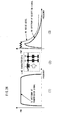
- an unnecessary bandwidth of a single sub-channel is orthogonal, as shown in Fig.28, at carrier points of regular intervals in a bandwidth of the DMT system and the OFDM system, the unnecessary bandwidth (side lobe) of each sub-channel extends to low and high frequency bands in an attenuating waveform of sinx/x.
- noises led from outside and noises generated by an apparatus connected to a transmission line are carried on the transmission line.
- a system for reducing this noise there are integration or averaging on a frequency axis in a QAM transmission line, averaging on a time axis/frequency axis in a spread spectrum system, or the like.
- Fig.29(1) shows a noise N1 on a reception signal RX, where noises of different intensities depending on the frequency band arise, and a larger noise locally arises.
- an error correcting code such as Reed-Solomon code.
- the ability of correcting errors is exceeded, which disables the correction.
- a conventional technology to deal with such an issue includes averaging of noises called interleave (interleaving).
- interleave interleaving
- the transmission side rearranges the transmission data at random to be transmitted, and the reception side receives the reception signal RX including an uneven noise N1 as shown in Fig.29(1).
- the reception side rearranges the received data to be restored to the original data.
- burst errors or the like due to the noise N1 are distributed as shown in Fig.29(2), thereby enabling the correction by using the error correction code.
- the interleave technology rearranges the transmission data at random, distributes error arising positions, and corrects this distributed error (the number of error bits is small) by using the error correction code.
- a method and an apparatus for a data transmission according to the present invention multiplex data to be transmitted by using a Hadamard (hereinafter, occasionally abbreviated as ADM) sequence. Also, a method and an apparatus for a data transmission according to the present invention distribute received data by using the Hadamard sequence.
- ADM Hadamard
- frame synchronization of multiplexing on a transmission side with distribution on a reception side may be performed by transmitting a frame synchronizing signal (e.g. an amplitude-modulated synchronizing signal) of multiplexed data on the transmission side, and by distributing the received data in synchronization with the frame synchronizing signal extracted on the reception side.
- a frame synchronizing signal e.g. an amplitude-modulated synchronizing signal
- Fig.1 shows a principle of a method and an apparatus for a data transmission according to the present invention.
- a Hadamard multiplexer 61 on the transmission side, multiplexes data by using a Hadamard sequence.
- a Hadamard distributor 74 distributes the data by using the Hadamard sequence to be restored to the original data.
- Eq.(1) shows a Hadamard matrix of the second order. If the elements of this matrix are multiplied in a vertical direction and the sum of them is obtained, it assumes "0". This indicates that the Hadamard matrix has an orthogonal relationship. It is to be noted that an inverse matrix of a Hadamard matrix assumes the same matrix as the original matrix.
- the Hadamard matrix is an orthogonal matrix, it is possible to multiplex data by using the Hadamard transform and to restore the original data by distributing the multiplexed data with the Hadamard transform.
- Eq.(2) shows output data ((x + y), (x-y)) when the Hadamard transform is performed to input data (x, y).
- Eq.(3) shows the case where the Hadamard inverse transform is performed to the output data to which the Hadamard transform is performed. The transform result assumes the original input data (x, y), if coefficients are neglected.
- Eq.(4) shows a Hadamard matrix of the fourth order. Since the inverse matrix of this is the same as the original matrix, and the matrix in which rows and columns are exchanged with each other is the same as the original matrix, this matrix is an orthogonal matrix.
- Eq.(5) shows output data in the case where the Hadamard transform is performed to input data (w, x, y, z).
- Eq.(6) shows data obtained by performing the Hadamard inverse transform to this output data. It is seen that the original data (w, x, y, z) is restored if coefficients are neglected.
- noises carried on the data after the Hadamard transform are reduced compared to noises carried on the data directly transmitted without the Hadamard transform/inverse transform.
- data "w" in Eq.(6) for the inverse transform is obtained by averaging input signals (w + x + y + z), (w-x + y-z), (w + x-y-z), and (w-x-y + z) respectively including noises.
- the Hadamard transform/inverse transform has an integration (averaging) effect in the same way as the other orthogonal transform, and is resistant to a noise variation.
- the method and the apparatus for the data transmission according to the present invention may multiplex data by using an orthogonal sequence; transmit the multiplexed data to a transparent transmission line; receive data from a transparent transmission line; and distribute the data by using an orthogonal sequence.
- data is multiplexed on the transmission side by using an orthogonal sequence (e.g. Hadamard sequence) to be transmitted to a transparent transmission line 70.
- an orthogonal sequence e.g. Hadamard sequence
- the (multiplexed) data received from the transparent transmission line 70 is distributed by using the orthogonal sequence (e.g. Hadamard sequence) to be restored to the original data.
- a Wavelet transform a quadrature mirror filter, a DMT system, an OFDM system, or the like may be used in addition to the Hadamard transform.
- a QAM transmission line may be used as the transparent transmission line.
- a spread spectrum transmission line may be used as the transparent transmission line.
- the method and the apparatus for the data transmission according to the present invention may multiplex data by using a Hadamard sequence, further multiplex the multiplexed data by using an orthogonal sequence, and transmit this multiplexed data to a transparent transmission line. Also, the method and the apparatus for the data transmission according to the present invention may distribute data received from the transparent transmission line by using an orthogonal sequence, and further distribute the distributed data by using a Hadamard sequence.
- orthogonal sequence multiplexing 66 is performed, so that the multiplexed data is transmitted to the Nyquist transmission line 70.
- the data is further distributed by using the Hadamard sequence to be restored to the original data.
- the method and the apparatus for the data transmission according to the present invention may multiplex data by using a first orthogonal sequence; interleave the multiplexed data on a frequency (domain) axis and a time (domain) axis; and multiplex the interleaved multiplexed data by using a second orthogonal sequence. Also, on the reception side, the method and the apparatus for the data transmission according to the present invention may distribute data by using the second orthogonal sequence; deinterleave the distributed data on a frequency axis and a time axis; and distribute the deinterleaved data by using the first orthogonal sequence.
- averaging is performed by multiplexing 67 using the first orthogonal sequence and by interleave 62 using a frequency axis interleave and a time axis interleave, and equalization is performed by multiplexing 66 using the second orthogonal sequence.
- the average processing is performed by deinterleave 73 with the time axis deinterleave and the frequency axis deinterleave, and by distribution 77 with the first orthogonal sequence.
- a PN sequence may be used for the interleave and the deinterleave.
- interleave can be performed at a high speed, thereby enabling noises to be more averaged.
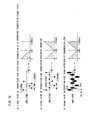
- Fig.3 shows a state where an interleaver is provided and channels CH1-CH16 are spread only along a frequency axis "f' after multiplexing data with e.g. the Hadamard transform (see hatched portion).
- This spread is performed by using a PN sequence (1, 1, 1, 1, 0, 1, 0, 1, 1, 0, 0, 1, 0, 0, 0), and data of each channel CH1-CH16 is spread to a channel CH of a value determined by e.g. 4 bits sequentially taken out of the PN sequence.
- Fig.4 shows a state where the interleaver provided on the transmission side spreads data along a time axis "t" in addition to the spread of the frequency axis "f' shown in Fig.3.
- the spread along the time axis "t” is performed by using the PN sequence, and data at each time of t1-t16 is spread to a time "t" of a value determined by 4 bits sequentially taken out of the PN sequence.
- Fig.5 shows a diagram in which a correlation of the PN sequence (2 values, 15 chips) is obtained, and shows an orthogonality of the PN sequence.
- the reference PN sequence (see hatched portion) is transformed into a basic sequence (1, 1, 1, 1, -1, 1, -1, 1, 1, -1, -1, 1, -1, -1, -1) obtained by changing the value "0" in the reference PN sequence to "-1".
- the calculation time is shortened compared with the case where other orthogonal sequences are used, thereby enabling a high-speed data transmission.
- Fig.6 shows averaging of noise by an interleaver of the present invention, which are the same as the above-mentioned Fig.29.
- the prior art distributed noise N2 shown in Fig.29(2) actually looks like the prior art distributed noise N3 in Fig.6(2).
- the high-speed interleaver of the present invention it becomes possible to perform averaging like a noise N4 distributed by the present invention of Fig.6(2), and to make corrections with error correction codes.
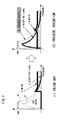
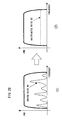
- the colored noise observed macroscopically in that way is noticed, and as shown in Fig.7(2), the noise component N1 dominant in the low frequency band is positively canceled to shift the S/N value to plus, so that the extraction of a reception signal S buried in the low frequency band, with a comparatively high level, is attempted.
- the prevent invention realizes a method and an apparatus for a data transmission for multiplexing data by using an orthogonal sequence on the transmission side and for periodically inserting zero-points into this multiplexed data, for interpolating a noise component of the data by using the zero-points periodically included in the received data on the reception side, for regenerating the original data transmitted by subtracting the noise components from the data, and for distributing the original data regenerated by using the orthogonal sequence.
- the zero-points may be a signal (hereinafter, occasionally referred to as specific signal) in which a time, an amplitude, and a phase are specified.
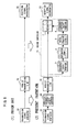
- Fig.8(1) shows a prior art data transmission system (hereinafter, referred to as transmission/reception system) of a signal, in which a transmission signal from a transmission signal generator 32 multiplexing transmission data by using an orthogonal sequence is sent to a reception signal regenerator 33 distributing reception data by using the orthogonal sequence through a Nyquist transmission line 70 as a transparent transmission line.
- transmission/reception system a prior art data transmission system of a signal, in which a transmission signal from a transmission signal generator 32 multiplexing transmission data by using an orthogonal sequence is sent to a reception signal regenerator 33 distributing reception data by using the orthogonal sequence through a Nyquist transmission line 70 as a transparent transmission line.
- an inserter (inserting portion) 64 of a specific signal or a zero-point (hereinafter, generally referred to as zero-point) is provided between the transmission signal generator 32 and the Nyquist transmission line 70 in such a transmission/reception system, and a noise canceler 71 is provided between the Nyquist transmission line 70 and the reception signal regenerator 33.
- the noise canceler 71 is composed of a frequency shift portion 3, a decimator (DCM) (decimating portion) 4, an interpolator (IPL) (interpolating portion) 5, a frequency reverse shift portion 6, and a subtracter (subtracting portion) 7, as described later.
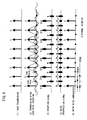
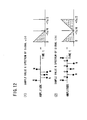
- the symbol rate of the transmission signal generated by the transmission signal generator 32 is assumed to be e.g. 192 kB as shown in Fig.9(1). If such a transmission signal is provided to the zero-point inserter 64, the zero-point inserter 64 inserts the zero-point, as shown in Fig.9(2), into the transmission signal of Fig.9(1) to be transmitted to the Nyquist transmission line 70. If the signal S is also transmitted at the same rate, the transmission rate assumes 384 kB.
- the reception side receives the reception signal S and the zero-point on which the noise N of the transmission line 70 is respectively put.
- the noise canceler 71 cancels the signal S including the noise N (S+N), and leaves only the noise N at the zero-point. Then, as shown in Fig.9(4), a noise interpolation signal N' is generated at each reception signal point from the noises N on both sides.
- the noise canceler 71 further subtracts the noise interpolation signal N' shown in Fig.9(4) from the reception signal shown in Fig.9(3), so that the noise N assumes N-N' as shown in Fig.9(5).
- the signal (corresponding to the transmission signal), having substantially removed therefrom the noise, only composed of the signal component S can be regenerated.
- the above-mentioned transmission signal is firstly transmitted at the rate of 192 kB as shown in Fig.10(1).
- the spectrum in this case is shown by the scalar, in which the abscissa denotes frequency bandwidth kHz, in the right of Fig.10(1).
- the zero-points are inserted into such a transmission signal, the zero-points are to be inserted into signal points as shown in Fig.10(2), so that the frequency bandwidth after the insertion assumes 384 kB. In this case, a spectrum is copied around +192 kHz can be obtained.
- the reception signal at the time when such a transmission signal into which the zero-points are inserted is transmitted to the reception side assumes the noise components N being overlapped with the signals S and the zero-points respectively, as shown in Fig.10(3).
- the spectrum in this case is the same as that of the transmission signal shown in Fig.10(2).
- the inverted signal in this case has a coefficient (-1) n because the inversion is made only to the signal component at the signal point.
- decimation signal u(n) provided to the interpolator 5 shown in Fig.8 would exhibit the operations shown in Fig.12.
- the signal u(n) from the decimator 4 is only composed of the noise component having the sample value and the spectrum shown in Fig.12(1).
- the signal has the same transmission rate as the reception signal S(n) shown in Fig.11(1) and has only the noise component.
- the transmission signal into which the zero-points are inserted shown in Fig.10(2) can be obtained.
- Fig.13 shows how the noise component is canceled by paying attention only to the noise component.
- the transmission signal has the transmission bandwidth of 192 kB ( ⁇ 96 kB), and the zero-points are inserted thereto, the bandwidth is doubled, so that the copied component is generated to be sent to the Nyquist transmission line 70.
- the noise distribution firstly extends over ⁇ 192 kHz.
- the noise level is high especially in the left half of the frequency bandwidth of -192-0 kHz as shown in Fig.7, and is low in the frequency bandwidth of 0-+192 kHz.
- a noise component A+B will be shifted by +96 kHz for the noise characteristic 1 ⁇ , as shown in a noise characteristic 2 ⁇ .
- a noise component D in the noise characteristic 1 ⁇ will be aliased to -192 kHz - -96 kHz.
- the noise bandwidth for which the interpolation (interpolated prediction) is desired to be performed is shifted to the interpolation bandwidth, thereby more effectively canceling the noise.
- the frequency becomes half. Therefore, the noise component A is aliased in +96-+192 kHz, the noise component B is aliased to -192 - -96 kHz, the noise component C is aliased to -96-0 kHz, and the noise component D is aliased to 0 - +96 kHz.
- the bandwidth where the aliased component becomes the least is selected here.
- the interpolator 5 interpolates the zero-points and performs a filter canceling of the noise components A+C and B+D on both sides, the noise components A+C and B+D only between -96-+96 kHz remain as shown in a noise characteristic 4 ⁇ .
- the noise components A+C and B+D only between -192-0 kHz remain as shown in a noise characteristic 5 ⁇ .
- the subtracter 7 subtracts such noise components from the entire noise components shown in the characteristic 1 ⁇ thereby completely canceling the noise components A and B between -192-0 kHz as shown in a characteristic 6 ⁇ . It is to be noted that although the noise components C and D remain, their noise level is low, as shown in Fig.7(2), so that the S/N value is not greatly influenced.
- the reception signal from which the noise is canceled in that way is regenerated substantially corresponding to the transmission signal.
- the reason for performing the frequency shift as mentioned above is because the interpolation bandwidth is set e.g. to the bandwidth where the most noises exist (in low frequency band in this example) to select the high frequency band with less noise for the aliased frequency bandwidth.
- Fig.14 show various patterns of the zero-point insertion.
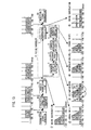
- Fig.14(1) shows the case where the zero-points are inserted into every 4th signal S, whereby the interpolated noise bandwidth assumes 96 kHz.
- Fig.14(2) shows a case where the zero-points are inserted into every 3rd signal S, whereby the interpolated noise bandwidth assumes 128 kHz.
- Fig.14(3) shows a case where the zero-points are inserted into every other signal in the same way as the above-mentioned example, whereby the interpolated noise bandwidth assumes 192 kHz.
- Fig.14(4) shows an example in which two zero-points are inserted between the signals S, whereby the interpolated noise bandwidth assumes 256 kHz.
- Fig.14(5) shows an example in which three zero-points are inserted between signals S, whereby the interpolated noise bandwidth assumes 288 kHz.
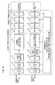
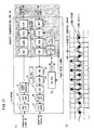
- Fig.15 shows an embodiment (1) of an apparatus for realizing a data transmission method according to the present invention.
- This apparatus is different from the modem 10 shown in Fig.27 in that a Hadamard multiplexer 61 is inserted instead of the roll-off filter 14 and the modulation circuit 15, and a Hadamard distributor 74 is inserted instead of the carrier automatic phase controller 26, the equalizer 25, the roll-off filter 22, and the demodulation circuit 21.
- the transmission side is provided with a synchronizing signal adder (not shown) for adding a Hadamard master frame synchronizing signal which indicates a synchronization of a block to which a Hadamard transform is performed.
- the reception side is provided with a Hadamard master frame synchronizer 80 for extracting the synchronizing signal to be provided to the Hadamard distributor 74.
- transmission clock generation circuit (TX-CLK) 18 and the reception clock distributor 30 shown in Fig.27 are omitted in Fig.15.
- the Hadamard multiplexer 61 multiplexes data received from the signal point generator 13 after performing the Hadamard transform.
- the multiplexed data is transformed into analog data by the D/A converter 16 to be transmitted as a signal of only a low frequency band including a frequency bandwidth (10 - 450 kHz) of a power carrier wave by the LPF 17, when the transmission line is e.g. a power line.
- the BPF 19 When the transmission signal from the transmission line is received through the reception line, the BPF 19 firstly extracts only a predetermined frequency band components (10 - 450 kHz in case of power carrier modem) to be restored to a digital signal by the A/D converter 20.
- the synchronizer 80 extracts a Hadamard frame synchronizing signal from the received digital signal.
- the Hadamard distributor 74 distributes (demultiplexes) the received data by using the inverse Hadamard transform in synchronization with the synchronizing signal.
- the processing load is lightened compared with e.g. the DMT system or the OFDM system, and it becomes possible to accommodate to high-speed data transmission.
- a multi-carrier system enables an equalization corresponding to the line characteristic.
- Fig.16 shows an embodiment (2) of the present invention, which is different from the embodiment (1) shown in Fig.15 in that the Nyquist transmission line (e.g. QAM transmission line) 70 which is the transparent transmission line shown in Fig.27 is connected to the subsequent stage of the Hadamard multiplexer 61, instead of the D/A converter 16 and the LPF 17 on the transmission side, and the Hadamard distributor 74 is connected to the Nyquist transmission line 70 on the reception side.
- the Nyquist transmission line e.g. QAM transmission line
- a guard time adder (shown in the same function block as the Hadamard multiplexer for convenience sake in Fig.16) is inserted between the Hadamard multiplexer 61 and the Nyquist transmission line 70 for multi-path countermeasures on the transmission side, and a guard time remover (shown in the same function block as the Hadamard distributor for convenience sake like the guard time adder) is inserted between the Nyquist transmission line 70 and the Hadamard distributor 74.
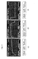
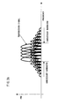
- Fig.17 shows frequency characteristics of the transmission side output of the Nyquist transmission line 70, i.e. the output of the low-pass filter 17.
- Figs.17(1)-(3) representation ranges of frequencies in abscissa are respectively 0-100 kHz, 0-500 kHz, and 0-5.0 MHz, and the same waveform is shown.
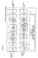
- Fig.18 shows an embodiment (3) of the present invention, which is different from the embodiment (1) in that a time/frequency interleaver 62 and a DMT portion 63 of a multi-carrier system which is an orthogonal sequence multiplexing system are connected in cascade between the Hadamard multiplexer 61 and the D/A converter 16 of the embodiment (1) on the transmission side, and a DMT portion 72 and a time/frequency deinterleaver 73 are connected in cascade between the A/D converter 20 and the Hadamard distributor 74 on the reception side.
- a time/frequency interleaver 62 and a DMT portion 63 of a multi-carrier system which is an orthogonal sequence multiplexing system are connected in cascade between the Hadamard multiplexer 61 and the D/A converter 16 of the embodiment (1) on the transmission side
- a DMT portion 72 and a time/frequency deinterleaver 73 are connected in cascade between the A/D converter 20 and the Hadamard distributor 74 on the reception side.
- an amplitude phase pull-in portion 81 shifts to the subsequent stage of the DMT portion 72 for timing.
- the guard time adder shown in the same functional block as the DMT portion 63 for convenience sake in Fig.18
- the guard time remover is connected between the A/D converter 20 and the DMT portion 72.
- the time/frequency interleaver 62 executes the frequency axis interleave and the time axis interleave shown in Fig.4 to the multiplexing data from the Hadamard multiplexer 61.
- the guard time is added to the data to be transmitted to the transmission line through the D/A converter 16 and the LPF 17.
- the guard time remover-DMT portion 72 removes the guard time of the data received through the reception line, the BPF 19, and the A/D converter 20, and then the DMT portion 72 demodulates the signal to be provided to the time/frequency deinterleaver 73 through the amplitude phase pull-in portion 81.
- the deinterleaver 73 executes deinterleave on the time axis and the frequency axis, and averages the noises put on the transmission /reception line to be provided to the Hadamard distributor 74.
- the Hadamard distributor 74 distributes the data in which the noises are averaged, and then executes an inverse Hadamard transform to the distributed data to be provided to the DEC 27.
- the Hadamard multiplexer (orthogonal sequence multiplexer) 61 and the time/frequency interleaver 62 perform noise average processing, and the DMT (orthogonal modulation) performs equalization, so that the function of averaging is separated from that of equalization and the processing is simplified, thereby enabling both of averaging and equalization to be performed.
- the time/frequency deinterleaver 73 and the Hadamard distributor 74 perform the average processing, and the DMT 72 side performs the equalization processing.
- processing is separated and simplified, thereby enabling both of averaging and equalization to be performed.
- Fig.19 shows an embodiment (4) of the present invention, which is different from that of the embodiment (3) shown in Fig.18 in that the Nyquist transmission line 70 is directly connected to the DMT-guard time adder 63 on the transmission side and to the guard time remover-DMT portion 72 on the reception side.
- the removal of the unnecessary bandwidths (narrowing the bandwidth) by the Nyquist transmission line 70 shown in the embodiment (2) is made possible without occurrences of the intersymbol interference, in addition to the speed enhancement of the data transmission, the reduction of the transmission error, and both of the average and equalization processing shown in the embodiment (3).
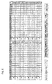
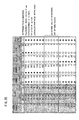
- Fig.20 is a table for obtaining the optimal carrier number in the method and the apparatus for the data transmission according to the present invention.
- This table shows (1) transmission rate (Bauds) per element, (2) transmission time ( ⁇ s) of a single element, (3) tap number required for a transversal filter used for realizing each filter, (4) cycle number (MIPS) required for processing, (5) peak value (dB), and (6) equalization range (dB) for a carrier number.
- Fig.21 shows an embodiment (5) of the present invention, which is different from the embodiment (4) shown in Fig.19 in that the zero-point inserter 64 is connected in cascade between the DMT-guard time adder 63 and the Nyquist transmission line 70 on the transmission side, and the noise canceler 71 is connected in cascade between the Nyquist transmission line 70 and the guard time remover-DMT portion 72 on the reception side.
- Fig.22 shows an embodiment (6) of a data transmission apparatus (modem) 10 according to the present invention.
- This modem 10 has the same arrangement as that of the prior art modem 10 except the above-mentioned zero-point (specific signal) inserter 64 and the noise canceler 71.
- the signal point generator 13 transmits a transmission signal as shown in Figs.3(1) and 4(1). Zero-points are inserted into the transmission signal by the zero-point inserter 64 of the present invention to be transmitted to the Nyquist transmission line 70.
- a reception signal received by the Nyquist transmission line 70 through the transmission line ⁇ reception line is transmitted to the equalizer 25 from the roll-off filter 22 after the noise component of the transmission line is canceled by the noise canceler 71 of the present invention.
- Fig.23 shows an embodiment of a noise canceler 71 shown in Fig.22, which corresponds to the noise canceler 71 shown in Fig.8.
- a reception signal A (384 kB) is outputted as a signal C whose frequency is shifted by a desired rotation vector signal B by the frequency shift portion 3.
- the signal C is sent to the decimator 4, where the signal is converted into a signal D (192 kB) having only the noise component shown in Fig.11(4), based on the zero-point signal (192 kB) extracted from the PLL circuit 24 shown in Fig.22.
- the signal D is sent to the interpolator 5 to be outputted as a signal E (384 kB) interpolated by the filter process. Since the signal E is sent to the frequency reverse shift portion 6 and shifted toward the reverse direction to the rotation vector signal B used by the frequency shift portion 3, the signal is rotated in the reverse direction by a signal F composing a conjugated complex number with the signal B to be outputted as a signal G. It is to be noted that a delay circuit 8 is provided on the course in order that the signal F is adjusted to the timing of the output signal of the interpolator 5.
- the output signal G of the frequency reverse shift portion 6 is subtracted from the reception signal A by the subtracter 7 to assume an output signal K. It is to be noted that a delay circuit 9 is also provided to the reception signal A in order to adjust the timing to the output signal of the interpolator 5 in this case.
- the signal K that is the reception signal A from which the noise component is canceled is outputted from the noise canceler 71.
- Fig.24 shows an embodiment of the interpolator 5 shown in Fig.23, which is composed of a zero-point inserter 51 and an interpolation filter 52.
- the zero-point inserter 51 inserts the zero-points between the noises, as shown in Fig.12(2), with respect to the signal D (192 kB) composed of only the noise component outputted from the decimator 4 to be provided to the interpolation filter 52 as a signal of 384 kB transmission bandwidth.
- the interpolation filter 52 can be composed of a transversal filter, which can compose various filters with a delay circuit 521 and filter coefficients C1-Cn of a multiplication circuit 522.
- the interpolation signal E outputted therefrom is outputted as a signal having a certain amplitude where the noise component N' at each zero-point is interpolated by the noise components N on both sides of the zero-point at the signal shown in Fig.9(4).
- Fig.25 shows an embodiment of the timing extractor 23 and the VCXO type PLL circuit 24 shown in Fig.22.
- the timing extractor 23 is composed of a power calculation circuit (PWR) 231, a band-pass filter 232, and a vectorizing circuit 233.
- the PLL circuit 24 is composed of a comparator 241, a low-pass filter 242, a secondary PLL circuit 243, a D/A conversion circuit 244, a VCXO (Voltage Controlled Crystal Oscillator) circuit 245, and a frequency divider 246.
- PWR power calculation circuit
- the PLL circuit 24 is composed of a comparator 241, a low-pass filter 242, a secondary PLL circuit 243, a D/A conversion circuit 244, a VCXO (Voltage Controlled Crystal Oscillator) circuit 245, and a frequency divider 246.
- VCW Voltage Controlled Crystal Oscillator
- the vector signal outputted from the roll-off filter 22 is squared by the power calculation circuit 231 to calculate the power.
- the power value thus obtained is passed through the band-pass filter 232. Since the band-pass filter having the center frequency of 192 kHz is used in this example, desired zero-point signal information is outputted to the vectorizing circuit 233.
- the vectorizing circuit 233 vectorizes the input signal by synthesizing the input signal with a signal whose phase is different by 90 degrees, and provides the same to the PLL circuit 24 as timing phase information.
- the timing phase information from the vectorizing circuit 233 is firstly compared with the phase of a reference point preliminarily known at the comparator 241.
- the phase difference is filtered to include only a low component by the low-pass filter 242, so that the controlled voltage of the VCXO 245 is controlled by the secondary PLL circuit 243 composed of two integrators and the D/A conversion circuit 244.
- phase information is fed back to the comparator 241 to be compared with the phase at the reference point.
- the phase difference between the timing phase information from the vectorizing circuit 233 and the reference point is pulled in or nullified thereby enabling the extraction of the zero-point signal whose synchronization is established.
- the sample timing signal to the A/D converter 16 is outputted from the VCXO circuit 245, and is finally fed back to the comparator 241 to compose a phase locked loop.
- a data transmission apparatus is arranged such that a Hadamard multiplexing/distribution, or a quadrature mirror filter multiplexing/distribution is performed. Therefore, it becomes possible to reduce load of a processing cycle number.
- the data transmission apparatus is arranged such that data is multiplexed by using an orthogonal sequence, the multiplexed data is transmitted to a transparent transmission line, and the data received from the transparent transmission line is distributed by using the orthogonal sequence. Therefore, it becomes possible to remove and narrow unnecessary bandwidths without occurrences of intersymbol interference.
- the line equalization becomes easy. Furthermore, it becomes possible to accommodate to a multi-path by providing a guard time.
Landscapes
- Engineering & Computer Science (AREA)
- Computer Networks & Wireless Communication (AREA)
- Signal Processing (AREA)
- Noise Elimination (AREA)
- Synchronisation In Digital Transmission Systems (AREA)
- Digital Transmission Methods That Use Modulated Carrier Waves (AREA)
Abstract
In a method and an apparatus for a data transmission in
transmission media which vary depending on noises from outside,
connected apparatuses, connection methods such as multi-path, or the
like, a data transmission (1) in which processing load is light, (2) in
which line equalization is easy and which is adaptable to the
multi-path, or (3) which is resistant to a noise variation is realized.
A Hadamard multiplexing/distribution, or a quadrature mirror
filter multiplexing/distribution is performed. Also, data is multiplexed
by using an orthogonal sequence, the multiplexed data is transmitted
to a transparent transmission line, and the data received from the
transparent transmission line is distributed by using the orthogonal
sequence. Also, data is multiplexed by using the orthogonal sequence,
the multiplexed data is interleaved on a frequency axis and a time
axis, the interleaved multiplexed data is multiplexed by using the
orthogonal sequence, the multiplexed data is distributed by using the
orthogonal sequence, the distributed data is deinterleaved on the
frequency axis and the time axis, and the deinterleaved data is
distributed by using an orthogonal transform.
Description
The present invention relates to a method and an apparatus for
a data transmission, and in particular to a method and an apparatus
for a data transmission in transmission media in a variety of modes.
For a data transmission, various transmission media have
appeared depending on the applications and purposes. Characteristics
of such transmission media are complicatedly varied by characteristics
of apparatuses to be connected. Under circumstances of a multi-path
for example, a signal outputted from a transmission point is varied by
passing through various paths, and is synthesized on a reception point,
which leads to variations of its reception level and phase.
Also, some transmission media are accompanied by noises from
outside or apparatuses connected. As a result, a data quality
transmitted is to be considerably damaged.
In spite of such circumstances, necessities of the method and the
apparatus for the data transmission securing high-quality
communication have been remarkable in various industrial fields as
follows:
- Power-line carrier modem field which aims to realize a high-speed data transmission under circumstances with many noises such as in a power-line carrier;
- CATV modem, ADSL modem, and VDSL modem fields;
- 2.4G wireless LAN, wireless transmission field, optical transmission field, and the like;
- Magnetic disk or optical disk field of a high recording density;
- Multi valued transmission technology by semiconductor;
- Bar code scanner.
Hereinafter, transmission media having the above-mentioned
characteristics will be described by taking as an example a data
transmission by a power line, while the same applies to the other
fields as mentioned above.
A power-line modem has a 100 V/200 V household power line,
supplied to a household from a pole transformer, as a transmission
line, and is composed of a master set on a pole and a slave set in a
user's house.
The master is connected to the slave with a low voltage
distribution line between poles, a service wire from the low voltage
distribution line to the household, and an interior distribution line.
Generally, 5 slaves or so at the maximum are connected to a single
master.
Hereinafter, issues of the data transmission in the power-line
modem will be described referring to Fig.26. Fig.26(2) shows a line
characteristic of a household power line observed from a master. A low
voltage distribution line of 150 m appears to have an inductor L of
about 150 µ H, a service wire of 50 m appears to have a capacitor C1 of
about 0.1 µ F, and an interior distribution line to which capacitors for
preventing noises of various household electrical appliances are
connected appears to have a capacitor C2.
Consequently, the line characteristic appears to have a low-pass
filter. When the master transmits a transmission signal TX having a
spectrum shown in Fig.26(1), the slave receives a reception signal RX
having a spectrum shown in Fig.26(3) in which a high frequency band
greatly attenuates. For this reason, the high frequency band of the
reception signal RX is buried in a noise N in the worst case.
On the other hand, the low frequency band of the reception
signal RX is also buried in the noise N due to an inverter or the like of
e.g. the household electrical appliances, although its attenuations is
less compared with that in the high frequency band.
Also, since slaves distributed to a plurality of households are
connected to a single master in the power-line modem, issues of
multi-path due to a reflection of signals or the like occur in the same
way as the wireless transmission case.
Fig.27(1) shows an arrangement of a prior art data transmission
apparatus (modem) 10. This modem 10 performs scrambling a serial
transmission signal SD by a scrambler-S/P converter (SCR-S/P) 11 to
be converted into a parallel signal.
This parallel signal is converted from a Gray code (G) of which
the transmission signal SD is formed into a Natural code (N) which
can be calculated by a G/N converter-sum calculator 12. Furthermore,
a vector sum calculation corresponding to a difference calculator 28
used for detecting a phase on a reception side is performed to the
Natural code (N) to be transmitted to a Nyquist transmission line 70
(hatched portion) from a signal point generator 13.
The Nyquist transmission line 70 corresponds to a transparent
transmission line on which, as shown in Fig.27(2), signals are
transmitted with the interval of the transmission signal points being
made the Nyquist interval (384 kB in Fig.27(2)).
On the Nyquist transmission line 70, the waveform of the
transmission signal is shaped by a roll-off filter (ROF) 14. The output
signal of the roll-off filter 14 is modulated by a modulation circuit
(MOD) 15 and is further converted into an analog signal from a digital
signal by a D/A converter 16. Then, a low-pass filter (LPF) 17 extracts
a signal only in a low frequency band including a frequency band
(10-450 kHz) of a power carrier wave to be transmitted to the line.
When such a transmission signal is received through a reception
line, only predetermined frequency band components (10-450 kHz in
case of a power carrier modem) are firstly extracted by a band-pass
filter (BPF) 19, and restored to a digital signal by an A/D converter 20.
This digital signal is demodulated into a baseband signal by a
demodulation circuit (DEM) 21, and then the waveform is shaped by a
roll-off filter (ROF) 22.
The output of the roll-off filter 22 is sent to an equalizer (EQL)
25 and a timing extractor 23. The extractor 23 and a PLL control
circuit-Voltage Controlled Crystal Oscillator (PLL-VCXO) 24 extract a
timing signal, which is provided to the A/D converter 20 and a
reception clock distributor (RX-CLK) 30.
The equalizer 25 removes an intersymbol interference, and a
phase adjustment is performed by a carrier automatic phase controller
(CAPC) 26. Furthermore, a decision portion (DEC) 27 outputs signal
components from which noises are canceled.
A vector difference calculation opposite to the vector sum
calculation is performed by the difference calculator-N/G converter
(difference-N/G) 28 with the Natural code, and then the Natural code
is restored to the Gray code. The parallel Gray code is converted into a
serial signal by a P/S converter-descrambler (P/S-DSCR) 29, and
descrambling is performed to the signal to be outputted as a reception
signal RD.
As conventional technologies for resolving the above-mentioned
issues in the modem 10, (1) line equalization and guard time, (2)
removal of unnecessary bandwidth, and (3) averaging of noises will
now be described with issues thereof.
In order to equalize a transmission line which varies
complicatedly, there is a multi-carrier transmission system such as a
DMT (Discrete MultiTone) system and an OFDM (Orthogonal
Frequency Division Multiplexing) system.
In the multi-carrier transmission system, a frequency band in
use is divided into a plurality of narrow sub-channels, and in each
sub-channel data is transmitted by a Quadrature Amplitude
Modulation (hereinafter, abbreviated as QAM) system. A transmission
power and a bit number assigned to the transmission data can be
independently determined per sub-carrier.
Thus, the multi-carrier system can flexibly accommodate to
equalization of a line characteristic in which a signal attenuated
frequency characteristic, a noise frequency characteristic, or the like
vary complicatedly like a power line. For example, the multi-carrier
system removes a carrier band in which noises are prominent, thereby
enabling independent accommodation to the equalization per carrier.
Also, in the multi-carrier system, a transmission rate is
equivalently reduced by transmitting data in parallel on a plurality of
transmission channels, thereby facilitating a provision of a guard time
which is a solution to a multi-path issue.
However, both of the DMT system and the OFDM system use
IFFT (Inverse Fast Fourier Transform) and FFT (Fast Fourier
Transform) technologies, resulting in a heavy load with respect to
processing cycle number.
Although an unnecessary bandwidth of a single sub-channel is
orthogonal, as shown in Fig.28, at carrier points of regular intervals in
a bandwidth of the DMT system and the OFDM system, the
unnecessary bandwidth (side lobe) of each sub-channel extends to low
and high frequency bands in an attenuating waveform of sinx/x.
It is possible to remove this unnecessary bandwidth by providing
a filter outside.
As mentioned above, noises led from outside and noises
generated by an apparatus connected to a transmission line are
carried on the transmission line. As a system for reducing this noise,
there are integration or averaging on a frequency axis in a QAM
transmission line, averaging on a time axis/frequency axis in a spread
spectrum system, or the like.
This averaging of noises will now be described referring to a
schematic diagram shown in Fig.29.
Fig.29(1) shows a noise N1 on a reception signal RX, where
noises of different intensities depending on the frequency band arise,
and a larger noise locally arises. Generally, it is possible to correct a
bit error of data, which the noise N1 has generated, by an error
correcting code such as Reed-Solomon code. However, when the
number of error bits is large locally, the ability of correcting errors is
exceeded, which disables the correction.
A conventional technology to deal with such an issue includes
averaging of noises called interleave (interleaving). In this technology,
the transmission side rearranges the transmission data at random to
be transmitted, and the reception side receives the reception signal RX
including an uneven noise N1 as shown in Fig.29(1). The reception
side rearranges the received data to be restored to the original data.
At this time, burst errors or the like due to the noise N1 are
distributed as shown in Fig.29(2), thereby enabling the correction by
using the error correction code.
Namely, the interleave technology rearranges the transmission
data at random, distributes error arising positions, and corrects this
distributed error (the number of error bits is small) by using the error
correction code.
However, there is a limit of error correction based on the error
correction code. When the reception signal RX is buried in the noise N
as shown in Fig.26(3), the error correction is impossible.
It is accordingly an object of the present invention to provide a
method and an apparatus for a data transmission in transmission
media in a variety of modes depending on noises from outside,
connected apparatuses, a connection system such as multi-path, or the
like, whereby a data transmission (1) in which processing load is light,
(2) in which line equalization is easy and which is adaptable to the
multi-path, or (3) which is resistant to a noise variation is realized.
In order to achieve the above-mentioned object, a method and an
apparatus for a data transmission according to the present invention
multiplex data to be transmitted by using a Hadamard (hereinafter,
occasionally abbreviated as ADM) sequence. Also, a method and an
apparatus for a data transmission according to the present invention
distribute received data by using the Hadamard sequence.
It is to be noted that frame synchronization of multiplexing on a
transmission side with distribution on a reception side may be
performed by transmitting a frame synchronizing signal (e.g. an
amplitude-modulated synchronizing signal) of multiplexed data on the
transmission side, and by distributing the received data in
synchronization with the frame synchronizing signal extracted on the
reception side. This can be applied to a method and an apparatus for a
data transmission according to the present invention described later.
Fig.1 shows a principle of a method and an apparatus for a data
transmission according to the present invention.
In Fig.1(1), a Hadamard multiplexer 61, on the transmission side,
multiplexes data by using a Hadamard sequence. On the reception
side, a Hadamard distributor 74 distributes the data by using the
Hadamard sequence to be restored to the original data.
Hereinafter, a Hadamard transform and its inverse transform
will be described referring to the following equations (1)-(6):





Eq.(1) shows a Hadamard matrix of the second order. If the
elements of this matrix are multiplied in a vertical direction and the
sum of them is obtained, it assumes "0". This indicates that the
Hadamard matrix has an orthogonal relationship. It is to be noted
that an inverse matrix of a Hadamard matrix assumes the same
matrix as the original matrix.
Since the Hadamard matrix is an orthogonal matrix, it is
possible to multiplex data by using the Hadamard transform and to
restore the original data by distributing the multiplexed data with the
Hadamard transform.
Eq.(2) shows output data ((x + y), (x-y)) when the Hadamard
transform is performed to input data (x, y). Eq.(3) shows the case
where the Hadamard inverse transform is performed to the output
data to which the Hadamard transform is performed. The transform
result assumes the original input data (x, y), if coefficients are
neglected.
Eq.(4) shows a Hadamard matrix of the fourth order. Since the
inverse matrix of this is the same as the original matrix, and the
matrix in which rows and columns are exchanged with each other is
the same as the original matrix, this matrix is an orthogonal matrix.
Eq.(5) shows output data in the case where the Hadamard
transform is performed to input data (w, x, y, z). Eq.(6) shows data
obtained by performing the Hadamard inverse transform to this
output data. It is seen that the original data (w, x, y, z) is restored if
coefficients are neglected.
Thus, since the calculation of the Hadamard transform/inverse
transform is simple, the number of processing cycles is small
compared with an IFFT or an FFT, and the load for a DSP (Digital
Signal Processor) or the like generally used for processing apparatus
is reduced.
Also, when the original data is restored by the inverse transform,
noises carried on the data after the Hadamard transform are reduced
compared to noises carried on the data directly transmitted without
the Hadamard transform/inverse transform. This can be seen from the
fact that e.g. data "w" in Eq.(6) for the inverse transform is obtained
by averaging input signals (w + x + y + z), (w-x + y-z), (w + x-y-z),
and (w-x-y + z) respectively including noises.
Namely, it is seen that the Hadamard transform/inverse
transform has an integration (averaging) effect in the same way as the
other orthogonal transform, and is resistant to a noise variation.
In the same way as multiplexing and distribution using the
Hadamard sequence, as shown in Fig.1(2), it becomes possible to
reduce the load of averaging and the processing cycle number by
multiplexing and distribution using a quadrature (orthogonal) mirror
filter sequence. As for the processing cycle number, the effect is
especially large in a quadrature mirror filter sequence of lower-order.
As mentioned above, although unnecessary bandwidths of a
single channel become orthogonal at carrier points of regular intervals
in the DMT system and the OFDM system, as shown in Fig.2(1), the
unnecessary bandwidths extend to both of low and high frequency
bands in an attenuating waveform with a sinx/x curve. A transmission
line construction in a narrow bandwidth such as a Nyquist
transmission line of the QAM is difficult.
In order to solve this issue, the method and the apparatus for the
data transmission according to the present invention may multiplex
data by using an orthogonal sequence; transmit the multiplexed data
to a transparent transmission line; receive data from a transparent
transmission line; and distribute the data by using an orthogonal
sequence.
Namely, as shown in Fig.1(3), data is multiplexed on the
transmission side by using an orthogonal sequence (e.g. Hadamard
sequence) to be transmitted to a transparent transmission line 70. On
the reception side, the (multiplexed) data received from the
transparent transmission line 70 is distributed by using the
orthogonal sequence (e.g. Hadamard sequence) to be restored to the
original data.
Thus, as shown in Fig.2(2), by passing a transmission signal
through the transparent transmission line which has almost the same
bandwidth as that of the Nyquist transmission line 70 and outputs the
inputted signal unchanged, the unnecessary bandwidths are aliased
within the bandwidth so as to be removed. In this case, the aliased
signals cause no intersymbol interference since they are orthogonal to
each other.
It is to be noted that as the orthogonal sequence, a Wavelet
transform, a quadrature mirror filter, a DMT system, an OFDM
system, or the like may be used in addition to the Hadamard
transform.
Also, as the transparent transmission line, a QAM transmission
line, a spread spectrum transmission line, or the like may be used.
Also, the method and the apparatus for the data transmission
according to the present invention may multiplex data by using a
Hadamard sequence, further multiplex the multiplexed data by using
an orthogonal sequence, and transmit this multiplexed data to a
transparent transmission line. Also, the method and the apparatus for
the data transmission according to the present invention may
distribute data received from the transparent transmission line by
using an orthogonal sequence, and further distribute the distributed
data by using a Hadamard sequence.
Namely, as shown in Fig.1(4), after Hadamard multiplexing 61 is
performed to data by using the Hadamard sequence on the
transmission side, orthogonal sequence multiplexing 66 is performed,
so that the multiplexed data is transmitted to the Nyquist
transmission line 70.
On the reception side, after distributing the (multiplexed) data
received from the Nyquist transmission line 70 by using orthogonal
sequence distribution 76, the data is further distributed by using the
Hadamard sequence to be restored to the original data.
Thus, it becomes possible to remove unnecessary bandwidths
without generating intersymbol interference, and to enhance the
processing speed by using the Hadamard transform.
Also, in order to solve the above-mentioned noise variation issue,
on the transmission side, the method and the apparatus for the data
transmission according to the present invention may multiplex data
by using a first orthogonal sequence; interleave the multiplexed data
on a frequency (domain) axis and a time (domain) axis; and multiplex
the interleaved multiplexed data by using a second orthogonal
sequence. Also, on the reception side, the method and the apparatus
for the data transmission according to the present invention may
distribute data by using the second orthogonal sequence; deinterleave
the distributed data on a frequency axis and a time axis; and
distribute the deinterleaved data by using the first orthogonal
sequence.
Thus, as shown in Fig.1(5), on the transmission side, averaging
is performed by multiplexing 67 using the first orthogonal sequence
and by interleave 62 using a frequency axis interleave and a time axis
interleave, and equalization is performed by multiplexing 66 using the
second orthogonal sequence. Thus, by separating the average
processing from the equalization processing, the processing is made
simple, and it becomes possible to perform both of average and
equalization processing.
On the reception side, after performing the equalization
processing by multiplexing 76 with the second orthogonal sequence,
the average processing is performed by deinterleave 73 with the time
axis deinterleave and the frequency axis deinterleave, and by
distribution 77 with the first orthogonal sequence.
At this time, it is possible to shorten the processing time by
using the Hadamard sequence as the first orthogonal sequence. Also, a
PN sequence may be used for the interleave and the deinterleave.
Thus, compared with the prior art interleaver which performs a
bit interleave at a preceding stage of e.g. the DMT system (orthogonal
sequence), interleave can be performed at a high speed, thereby
enabling noises to be more averaged.
Fig.3 shows a state where an interleaver is provided and
channels CH1-CH16 are spread only along a frequency axis "f' after
multiplexing data with e.g. the Hadamard transform (see hatched
portion).
This spread is performed by using a PN sequence (1, 1, 1, 1, 0, 1,
0, 1, 1, 0, 0, 1, 0, 0, 0), and data of each channel CH1-CH16 is spread
to a channel CH of a value determined by e.g. 4 bits sequentially
taken out of the PN sequence.
Fig.4 shows a state where the interleaver provided on the
transmission side spreads data along a time axis "t" in addition to the
spread of the frequency axis "f' shown in Fig.3. In the same way as the
spread along the frequency axis "f', the spread along the time axis "t"
is performed by using the PN sequence, and data at each time of
t1-t16 is spread to a time "t" of a value determined by 4 bits
sequentially taken out of the PN sequence.
Fig.5 shows a diagram in which a correlation of the PN sequence
(2 values, 15 chips) is obtained, and shows an orthogonality of the PN
sequence. Firstly, supposing that the arrangement of signal points on
the transmission side of the PN sequence has 0=0° and 1=180° , it is
effected that 0→-1 and 1→1. Therefore, the reference PN sequence
(see hatched portion) is transformed into a basic sequence (1, 1, 1, 1, -1,
1, -1, 1, 1, -1, -1, 1, -1, -1, -1) obtained by changing the value "0" in the
reference PN sequence to "-1".
Furthermore, if a scalar product (product sum of elements in a
sequence) between this basic sequence and this basic sequence itself is
obtained, 0th correlation = "15". Then, if the scalar product between
the basic sequence and the 1st sequence obtained by rotating each
element of the basic sequence by a single element is obtained, +1st
correlation = "-1".
Similarly, if the scalar products between the basic sequence and
+2nd-+14th sequences rotated by 2-14 elements are respectively
obtained, all of +2nd-+14th correlations assume "-1". Since the basic
sequence is restored by the rotation of 15 times, +15th correlation
assumes "15" the same as the 0th correlation. Thus, the orthogonality
of the PN sequence, namely, 0th -+14th sequences are mutually
orthogonal without correlations being recognized.
It is to be noted that when a complex number signal is received
on the reception side, and the scalar product of the complex numbers,
i.e. the sum of the product with complex conjugate values, is obtained,
the same values as the transmitted 0=0° and 1=180° are obtained.
By using such a simple PN sequence for the interleaver, the
calculation time is shortened compared with the case where other
orthogonal sequences are used, thereby enabling a high-speed data
transmission.
Fig.6 shows averaging of noise by an interleaver of the present
invention, which are the same as the above-mentioned Fig.29. The
prior art distributed noise N2 shown in Fig.29(2) actually looks like
the prior art distributed noise N3 in Fig.6(2).
According to the high-speed interleaver of the present invention,
it becomes possible to perform averaging like a noise N4 distributed
by the present invention of Fig.6(2), and to make corrections with
error correction codes.
As having been shown in Fig.26, in case of a power-line
transmission line, a reception signal RX is buried in a noise N. In such
a case, even if averaging by the above-noted interleave is performed, it
is impossible to take out the reception signal RX from the noise N.
For example, even though a low frequency band (noise
component N1, signal component S1) where the level of a noise N is
high, as shown in Fig.7(1), is cut to transmit data only by using a high
frequency band, the S/N value remains minus.
On the other hand, if a noise in a power line is carefully observed
in Fig.26(3) and Fig.7(1), it is seen that there are a number of noises
emphasized in a low frequency band, in which if being microscopically
observed they are white noises while if being macroscopically observed
(from the entire frequency bandwidth), they are colored noises.
Namely, if being observed at any narrow bandwidth over the entire
frequency band, they are the same white noises.
Accordingly, in the present invention, the colored noise observed
macroscopically in that way is noticed, and as shown in Fig.7(2), the
noise component N1 dominant in the low frequency band is positively
canceled to shift the S/N value to plus, so that the extraction of a
reception signal S buried in the low frequency band, with a
comparatively high level, is attempted.
Therefore, the prevent invention realizes a method and an
apparatus for a data transmission for multiplexing data by using an
orthogonal sequence on the transmission side and for periodically
inserting zero-points into this multiplexed data, for interpolating a
noise component of the data by using the zero-points periodically
included in the received data on the reception side, for regenerating
the original data transmitted by subtracting the noise components
from the data, and for distributing the original data regenerated by
using the orthogonal sequence.
It is to be noted that the zero-points may be a signal (hereinafter,
occasionally referred to as specific signal) in which a time, an
amplitude, and a phase are specified.
Hereinafter, a principle of such a method and an apparatus for
noise canceling according to the present invention will be described
referring to the figures.
Fig.8(1) shows a prior art data transmission system (hereinafter,
referred to as transmission/reception system) of a signal, in which a
transmission signal from a transmission signal generator 32
multiplexing transmission data by using an orthogonal sequence is
sent to a reception signal regenerator 33 distributing reception data
by using the orthogonal sequence through a Nyquist transmission line
70 as a transparent transmission line.
In the present invention, as shown in Fig.8(2), an inserter
(inserting portion) 64 of a specific signal or a zero-point (hereinafter,
generally referred to as zero-point) is provided between the
transmission signal generator 32 and the Nyquist transmission line
70 in such a transmission/reception system, and a noise canceler 71 is
provided between the Nyquist transmission line 70 and the reception
signal regenerator 33. It is to be noted that the noise canceler 71 is
composed of a frequency shift portion 3, a decimator (DCM)
(decimating portion) 4, an interpolator (IPL) (interpolating portion) 5,
a frequency reverse shift portion 6, and a subtracter (subtracting
portion) 7, as described later.
First of all, the symbol rate of the transmission signal generated
by the transmission signal generator 32 is assumed to be e.g. 192 kB
as shown in Fig.9(1). If such a transmission signal is provided to the
zero-point inserter 64, the zero-point inserter 64 inserts the zero-point,
as shown in Fig.9(2), into the transmission signal of Fig.9(1) to be
transmitted to the Nyquist transmission line 70. If the signal S is also
transmitted at the same rate, the transmission rate assumes 384 kB.
The reception side, as shown in Fig.9(3), receives the reception
signal S and the zero-point on which the noise N of the transmission
line 70 is respectively put.
The noise canceler 71 cancels the signal S including the noise N
(S+N), and leaves only the noise N at the zero-point. Then, as shown
in Fig.9(4), a noise interpolation signal N' is generated at each
reception signal point from the noises N on both sides.
The noise canceler 71 further subtracts the noise interpolation
signal N' shown in Fig.9(4) from the reception signal shown in Fig.9(3),
so that the noise N assumes N-N' as shown in Fig.9(5). Thus, the
signal (corresponding to the transmission signal), having substantially
removed therefrom the noise, only composed of the signal component S
can be regenerated.
The operation of the noise canceler 71 will now be described in
more detail referring to Figs.10-12.
The above-mentioned transmission signal is firstly transmitted
at the rate of 192 kB as shown in Fig.10(1). The spectrum in this case
is shown by the scalar, in which the abscissa denotes frequency
bandwidth kHz, in the right of Fig.10(1).
When the zero-points are inserted into such a transmission
signal, the zero-points are to be inserted into signal points as shown in
Fig.10(2), so that the frequency bandwidth after the insertion assumes
384 kB. In this case, a spectrum is copied around +192 kHz can be
obtained.
The reception signal at the time when such a transmission signal
into which the zero-points are inserted is transmitted to the reception
side assumes the noise components N being overlapped with the
signals S and the zero-points respectively, as shown in Fig.10(3). The
spectrum in this case is the same as that of the transmission signal
shown in Fig.10(2).
The operation at the time when the reception signal is sent to
the decimator 4 after being shifted by the frequency shift portion 3 in
the noise canceler 71 is shown in Fig.11.
Namely, a sample value and a spectrum of a reception signal S(n)
are as shown in Fig.11(1), and the Z transformation A of the signal
S(n) is expressed by the following equation:
A=S(z)=ΣS(n)z-n
It is to be noted that the spectrum in the right of Fig.11(1) shows
that the noises are distributed over 0-fs/2 (fs is sample frequency) since
the noises are added by the transmission line 31.
The Z transformation B of the inversion signal of the reception
signal S(n) is expressed by the following equation:
B=Z[(-1)n S(n)]=S(-z)
The inverted signal in this case has a coefficient (-1)n because the
inversion is made only to the signal component at the signal point.
The Z transformation C of a signal t(n) obtained after adding the
inversion signal (-1)n*S(n) to the reception signal S(n) shown in
Fig.11(1) is given by the following equation:
C=Z[t(n)]=T(z)=(1/2)*[S(z)+S(-z)]
Namely, the amplitude at the signal point becomes zero, so that
not only the signal component S but also the noise component N
overlapped with the signal S is removed. The signal t(n) in which t(1),
t(3),,,= 0 is expressed by the following equation:
T(z)=Σt(2n)*Z-2n
A signal D after the signal point of the signal t(n) obtained in
this way shown in Fig.11(3) is decimated is expressed by the following
equation:
D=u(n)=T(z1/2 )
Since the transmission rate falls to 192 kB in this case, the
spectrum is aliased or folded as shown in Fig.11(4).
A final signal E=U(z) is given by the following equation:
E=[S(z1/2 )+S(-z1/2 )]/2
The thus obtained decimation signal u(n) provided to the
interpolator 5 shown in Fig.8 would exhibit the operations shown in
Fig.12.
Namely, the signal u(n) from the decimator 4 is only composed of
the noise component having the sample value and the spectrum shown
in Fig.12(1). The signal t(n) with the zero-point inserted into the noise
component has a sample value and a spectrum such as shown in
Fig.12(2), and the Z transformation A is expressed by the following
equation:
A=(z)=Σt(n)z-n
Since t(1), t(3),,,=0,
A=Σt(2n)z-n =u(n)z-2n
Then, the following equation is obtained:
T(z)=U(z2 )
If the zero-points are interpolated with the noise components N
on their both sides in the signal T(z), the signal has the same
transmission rate as the reception signal S(n) shown in Fig.11(1) and
has only the noise component.
Accordingly, by subtracting the interpolated signal from the
reception signal S(n), the transmission signal into which the
zero-points are inserted shown in Fig.10(2) can be obtained.
It is to be noted that in order to obtain the transmission signal
shown in Fig.10(1) the zero-points only have to be decimated.
While in the above description, how the transmission signal is
regenerated on the reception side has been mentioned, Fig.13 shows
how the noise component is canceled by paying attention only to the
noise component.
Namely, when the transmission signal has the transmission
bandwidth of 192 kB (±96 kB), and the zero-points are inserted
thereto, the bandwidth is doubled, so that the copied component is
generated to be sent to the Nyquist transmission line 70.
At the noise canceler 71, as shown in a noise distribution
characteristic 1 ○, the noise distribution firstly extends over ±192
kHz. The noise level is high especially in the left half of the frequency
bandwidth of -192-0 kHz as shown in Fig.7, and is low in the
frequency bandwidth of 0-+192 kHz.
When the frequency shift portion 3 shifts the frequency by +96
kHz in this state, a noise component A+B will be shifted by +96 kHz
for the noise characteristic 1 ○, as shown in a noise characteristic 2 ○.
With this shifting, a noise component D in the noise characteristic 1 ○
will be aliased to -192 kHz--96 kHz. Thus, the noise bandwidth for
which the interpolation (interpolated prediction) is desired to be
performed is shifted to the interpolation bandwidth, thereby more
effectively canceling the noise.
It is to be noted that the shift amount of +96 kHz is only one
example for convenience sake of description.
If the decimation operation is performed by the decimator 4 in
this state, the frequency becomes half. Therefore, the noise component
A is aliased in +96-+192 kHz, the noise component B is aliased to
-192--96 kHz, the noise component C is aliased to -96-0 kHz, and the
noise component D is aliased to 0-+96 kHz. The bandwidth where the
aliased component becomes the least is selected here.
If the interpolator 5 interpolates the zero-points and performs a
filter canceling of the noise components A+C and B+D on both sides,
the noise components A+C and B+D only between -96-+96 kHz
remain as shown in a noise characteristic 4 ○.
If the interpolated noise components are shifted in the reverse
direction to the above-mentioned frequency shift, that is, by -96 kHz,
the noise components A+C and B+D only between -192-0 kHz remain
as shown in a noise characteristic 5 ○.
Accordingly, the subtracter 7 subtracts such noise components
from the entire noise components shown in the characteristic 1 ○
thereby completely canceling the noise components A and B between
-192-0 kHz as shown in a characteristic 6 ○. It is to be noted that
although the noise components C and D remain, their noise level is
low, as shown in Fig.7(2), so that the S/N value is not greatly
influenced.
The reception signal from which the noise is canceled in that way
is regenerated substantially corresponding to the transmission signal.
It is to be noted that the reason for performing the frequency
shift as mentioned above is because the interpolation bandwidth is set
e.g. to the bandwidth where the most noises exist (in low frequency
band in this example) to select the high frequency band with less noise
for the aliased frequency bandwidth.
While in the above-mentioned Figs.9 and 10, a case where one
zero-point is inserted between the signal points has been mentioned,
Fig.14 show various patterns of the zero-point insertion.
Namely, Fig.14(1) shows the case where the zero-points are
inserted into every 4th signal S, whereby the interpolated noise
bandwidth assumes 96 kHz.
Also, Fig.14(2) shows a case where the zero-points are inserted
into every 3rd signal S, whereby the interpolated noise bandwidth
assumes 128 kHz.
Fig.14(3) shows a case where the zero-points are inserted into
every other signal in the same way as the above-mentioned example,
whereby the interpolated noise bandwidth assumes 192 kHz.
Fig.14(4) shows an example in which two zero-points are
inserted between the signals S, whereby the interpolated noise
bandwidth assumes 256 kHz.
Furthermore, Fig.14(5) shows an example in which three
zero-points are inserted between signals S, whereby the interpolated
noise bandwidth assumes 288 kHz.
By increasing the number of the zero-point as shown in
Figs.14(4) and 14(5), the noise canceling over a wider bandwidth is
made possible. Although the data transmission rate may decrease in
some cases in exchange for the increase of the noise proof, it becomes
possible to withstand worse circumstances.
Fig.15 shows an embodiment (1) of an apparatus for realizing a
data transmission method according to the present invention.
The arrangement of this apparatus is different from the modem
10 shown in Fig.27 in that a Hadamard multiplexer 61 is inserted
instead of the roll-off filter 14 and the modulation circuit 15, and a
Hadamard distributor 74 is inserted instead of the carrier automatic
phase controller 26, the equalizer 25, the roll-off filter 22, and the
demodulation circuit 21.
Also, the transmission side is provided with a synchronizing
signal adder (not shown) for adding a Hadamard master frame
synchronizing signal which indicates a synchronization of a block to
which a Hadamard transform is performed. The reception side is
provided with a Hadamard master frame synchronizer 80 for
extracting the synchronizing signal to be provided to the Hadamard
distributor 74.
It is to be noted that the transmission clock generation circuit
(TX-CLK) 18 and the reception clock distributor 30 shown in Fig.27
are omitted in Fig.15.
In operation, the Hadamard multiplexer 61 multiplexes data
received from the signal point generator 13 after performing the
Hadamard transform. The multiplexed data is transformed into
analog data by the D/A converter 16 to be transmitted as a signal of
only a low frequency band including a frequency bandwidth (10 - 450
kHz) of a power carrier wave by the LPF 17, when the transmission
line is e.g. a power line.
When the transmission signal from the transmission line is
received through the reception line, the BPF 19 firstly extracts only a
predetermined frequency band components (10 - 450 kHz in case of
power carrier modem) to be restored to a digital signal by the A/D
converter 20.
On the reception side, the synchronizer 80 extracts a Hadamard
frame synchronizing signal from the received digital signal. The
Hadamard distributor 74 distributes (demultiplexes) the received data
by using the inverse Hadamard transform in synchronization with the
synchronizing signal.
Thus, according to the method and the apparatus for the data
transmission by using the Hadamard multiplexing and the Hadamard
distribution, the processing load is lightened compared with e.g. the
DMT system or the OFDM system, and it becomes possible to
accommodate to high-speed data transmission. Also, a multi-carrier
system enables an equalization corresponding to the line
characteristic.
Similarly, it becomes possible to lighten the processing load of
quadrature mirror filter multiplexing/distribution.
Fig.16 shows an embodiment (2) of the present invention, which
is different from the embodiment (1) shown in Fig.15 in that the
Nyquist transmission line (e.g. QAM transmission line) 70 which is
the transparent transmission line shown in Fig.27 is connected to the
subsequent stage of the Hadamard multiplexer 61, instead of the D/A
converter 16 and the LPF 17 on the transmission side, and the
Hadamard distributor 74 is connected to the Nyquist transmission
line 70 on the reception side.
It is to be noted that in this embodiment (2) a guard time adder
(shown in the same function block as the Hadamard multiplexer for
convenience sake in Fig.16) is inserted between the Hadamard
multiplexer 61 and the Nyquist transmission line 70 for multi-path
countermeasures on the transmission side, and a guard time remover
(shown in the same function block as the Hadamard distributor for
convenience sake like the guard time adder) is inserted between the
Nyquist transmission line 70 and the Hadamard distributor 74.
Fig.17 shows frequency characteristics of the transmission side
output of the Nyquist transmission line 70, i.e. the output of the
low-pass filter 17. In Figs.17(1)-(3), representation ranges of
frequencies in abscissa are respectively 0-100 kHz, 0-500 kHz, and
0-5.0 MHz, and the same waveform is shown.
Thus, by connecting the Hadamard multiplexer 61 and the
Hadamard distributor 74 with the Nyquist transmission line 70, it is
recognized that the bandwidth is narrowed to the target bandwidth
10-450 kHz, and the unnecessary bandwidth is removed.
Fig.18 shows an embodiment (3) of the present invention, which
is different from the embodiment (1) in that a time/frequency
interleaver 62 and a DMT portion 63 of a multi-carrier system which
is an orthogonal sequence multiplexing system are connected in
cascade between the Hadamard multiplexer 61 and the D/A converter
16 of the embodiment (1) on the transmission side, and a DMT portion
72 and a time/frequency deinterleaver 73 are connected in cascade
between the A/D converter 20 and the Hadamard distributor 74 on the
reception side.
It is to be noted that an amplitude phase pull-in portion 81
(=frequency equalizer) shifts to the subsequent stage of the DMT
portion 72 for timing. Also, the guard time adder (shown in the same
functional block as the DMT portion 63 for convenience sake in Fig.18)
for multi-path countermeasures is connected between the DMT
portion 63 and the D/A converter 16, and the guard time remover
(shown in the same functional block as the DMT 72 for convenience
sake in Fig.18 like the adder) is connected between the A/D converter
20 and the DMT portion 72.
On the transmission side, the time/frequency interleaver 62
executes the frequency axis interleave and the time axis interleave
shown in Fig.4 to the multiplexing data from the Hadamard
multiplexer 61. After multi-carrier orthogonal sequence multiplexing
is performed to the interleaved data by the DMT-guard time adder 63,
the guard time is added to the data to be transmitted to the
transmission line through the D/A converter 16 and the LPF 17.
On the reception side, the guard time remover-DMT portion 72
removes the guard time of the data received through the reception line,
the BPF 19, and the A/D converter 20, and then the DMT portion 72
demodulates the signal to be provided to the time/frequency
deinterleaver 73 through the amplitude phase pull-in portion 81.
The deinterleaver 73 executes deinterleave on the time axis and
the frequency axis, and averages the noises put on the transmission
/reception line to be provided to the Hadamard distributor 74. The
Hadamard distributor 74 distributes the data in which the noises are
averaged, and then executes an inverse Hadamard transform to the
distributed data to be provided to the DEC 27.
Thus, on the transmission side, the Hadamard multiplexer
(orthogonal sequence multiplexer) 61 and the time/frequency
interleaver 62 perform noise average processing, and the DMT
(orthogonal modulation) performs equalization, so that the function of
averaging is separated from that of equalization and the processing is
simplified, thereby enabling both of averaging and equalization to be
performed.
Also on the reception side, the time/frequency deinterleaver 73
and the Hadamard distributor 74 perform the average processing, and
the DMT 72 side performs the equalization processing. Thus,
processing is separated and simplified, thereby enabling both of
averaging and equalization to be performed.
Thus, by enhancing the speed of the multiplexing and
distribution processing, it becomes possible to enhance the speed of
the data transmission, to perform the averaging of the noise at a
high-speed, to reduce the data transmission error, and to realize both
of averaging and equalization.
Fig.19 shows an embodiment (4) of the present invention, which
is different from that of the embodiment (3) shown in Fig.18 in that
the Nyquist transmission line 70 is directly connected to the
DMT-guard time adder 63 on the transmission side and to the guard
time remover-DMT portion 72 on the reception side.
Thus, the removal of the unnecessary bandwidths (narrowing
the bandwidth) by the Nyquist transmission line 70 shown in the
embodiment (2) is made possible without occurrences of the
intersymbol interference, in addition to the speed enhancement of the
data transmission, the reduction of the transmission error, and both of
the average and equalization processing shown in the embodiment (3).
Fig.20 is a table for obtaining the optimal carrier number in the
method and the apparatus for the data transmission according to the
present invention. This table shows (1) transmission rate (Bauds) per
element, (2) transmission time (µs) of a single element, (3) tap
number required for a transversal filter used for realizing each filter,
(4) cycle number (MIPS) required for processing, (5) peak value (dB),
and (6) equalization range (dB) for a carrier number.
Supposing that the determination condition is in the range of tap
number: 8-32, cycle number: ≦ 100 MIP, peak value: ≦ 12dB,
equalization range: within ±6dB, 12-16 carriers are determined to be
the optimal values.
Fig.21 shows an embodiment (5) of the present invention, which
is different from the embodiment (4) shown in Fig.19 in that the
zero-point inserter 64 is connected in cascade between the DMT-guard
time adder 63 and the Nyquist transmission line 70 on the
transmission side, and the noise canceler 71 is connected in cascade
between the Nyquist transmission line 70 and the guard time
remover-DMT portion 72 on the reception side.
Thus, in addition to the effect shown in the embodiment (4), it
becomes possible to cancel a noise whose level is high and which can
not be accommodated by the interleave or the like.
Detailed operation of the noise canceler based on the zero-point
inserter 64 and the noise canceler 71 will be described in the following
embodiment (6) together.
Fig.22 shows an embodiment (6) of a data transmission
apparatus (modem) 10 according to the present invention. This
modem 10 has the same arrangement as that of the prior art modem
10 except the above-mentioned zero-point (specific signal) inserter 64
and the noise canceler 71.
The signal point generator 13 transmits a transmission signal as
shown in Figs.3(1) and 4(1). Zero-points are inserted into the
transmission signal by the zero-point inserter 64 of the present
invention to be transmitted to the Nyquist transmission line 70.
A reception signal received by the Nyquist transmission line 70
through the transmission line → reception line is transmitted to the
equalizer 25 from the roll-off filter 22 after the noise component of the
transmission line is canceled by the noise canceler 71 of the present
invention.
Fig.23 shows an embodiment of a noise canceler 71 shown in
Fig.22, which corresponds to the noise canceler 71 shown in Fig.8.
Namely, a reception signal A (384 kB) is outputted as a signal C
whose frequency is shifted by a desired rotation vector signal B by the
frequency shift portion 3.
The signal C is sent to the decimator 4, where the signal is
converted into a signal D (192 kB) having only the noise component
shown in Fig.11(4), based on the zero-point signal (192 kB) extracted
from the PLL circuit 24 shown in Fig.22.
The signal D is sent to the interpolator 5 to be outputted as a
signal E (384 kB) interpolated by the filter process. Since the signal E
is sent to the frequency reverse shift portion 6 and shifted toward the
reverse direction to the rotation vector signal B used by the frequency
shift portion 3, the signal is rotated in the reverse direction by a signal
F composing a conjugated complex number with the signal B to be
outputted as a signal G. It is to be noted that a delay circuit 8 is
provided on the course in order that the signal F is adjusted to the
timing of the output signal of the interpolator 5.
The output signal G of the frequency reverse shift portion 6 is
subtracted from the reception signal A by the subtracter 7 to assume
an output signal K. It is to be noted that a delay circuit 9 is also
provided to the reception signal A in order to adjust the timing to the
output signal of the interpolator 5 in this case.
Thus, the signal K that is the reception signal A from which the
noise component is canceled is outputted from the noise canceler 71.
Fig.24 shows an embodiment of the interpolator 5 shown in
Fig.23, which is composed of a zero-point inserter 51 and an
interpolation filter 52.
Namely, the zero-point inserter 51 inserts the zero-points
between the noises, as shown in Fig.12(2), with respect to the signal D
(192 kB) composed of only the noise component outputted from the
decimator 4 to be provided to the interpolation filter 52 as a signal of
384 kB transmission bandwidth.
The interpolation filter 52 can be composed of a transversal filter,
which can compose various filters with a delay circuit 521 and filter
coefficients C1-Cn of a multiplication circuit 522. The interpolation
signal E outputted therefrom is outputted as a signal having a certain
amplitude where the noise component N' at each zero-point is
interpolated by the noise components N on both sides of the zero-point
at the signal shown in Fig.9(4).
Fig.25 shows an embodiment of the timing extractor 23 and the
VCXO type PLL circuit 24 shown in Fig.22. The timing extractor 23 is
composed of a power calculation circuit (PWR) 231, a band-pass filter
232, and a vectorizing circuit 233. The PLL circuit 24 is composed of a
comparator 241, a low-pass filter 242, a secondary PLL circuit 243, a
D/A conversion circuit 244, a VCXO (Voltage Controlled Crystal
Oscillator) circuit 245, and a frequency divider 246.
Namely, the vector signal outputted from the roll-off filter 22 is
squared by the power calculation circuit 231 to calculate the power.
The power value thus obtained is passed through the band-pass filter
232. Since the band-pass filter having the center frequency of 192 kHz
is used in this example, desired zero-point signal information is
outputted to the vectorizing circuit 233.
The vectorizing circuit 233 vectorizes the input signal by
synthesizing the input signal with a signal whose phase is different by
90 degrees, and provides the same to the PLL circuit 24 as timing
phase information.
In the PLL circuit 24, the timing phase information from the
vectorizing circuit 233 is firstly compared with the phase of a
reference point preliminarily known at the comparator 241. The phase
difference is filtered to include only a low component by the low-pass
filter 242, so that the controlled voltage of the VCXO 245 is controlled
by the secondary PLL circuit 243 composed of two integrators and the
D/A conversion circuit 244.
After performing the frequency division at the frequency divider
246, the phase information is fed back to the comparator 241 to be
compared with the phase at the reference point. Thus, the phase
difference between the timing phase information from the vectorizing
circuit 233 and the reference point is pulled in or nullified thereby
enabling the extraction of the zero-point signal whose synchronization
is established. Also, the sample timing signal to the A/D converter 16
is outputted from the VCXO circuit 245, and is finally fed back to the
comparator 241 to compose a phase locked loop.
As described above, a data transmission apparatus according to
the present invention is arranged such that a Hadamard
multiplexing/distribution, or a quadrature mirror filter
multiplexing/distribution is performed. Therefore, it becomes possible
to reduce load of a processing cycle number.
Also, the data transmission apparatus according to the present
invention is arranged such that data is multiplexed by using an
orthogonal sequence, the multiplexed data is transmitted to a
transparent transmission line, and the data received from the
transparent transmission line is distributed by using the orthogonal
sequence. Therefore, it becomes possible to remove and narrow
unnecessary bandwidths without occurrences of intersymbol
interference.
Also, it becomes possible to remove (narrow) the unnecessary
bandwidths and to enhance processing speed by multiplexing data by
using a Hadamard sequence, multiplexing the multiplexed data by
using the orthogonal sequence, transmitting the multiplexed data to
the transparent transmission line, distributing the data received from
the transparent transmission line with the orthogonal sequence, and
distributing the distributed data by the Hadamard sequence.
Also, it becomes possible to perform high-speed averaging and a
data transmission resistant to a noise variation by multiplexing data
by using the orthogonal sequence, interleaving the multiplexed data
on a frequency axis and a time axis, multiplexing the interleaved
multiplexed data by using the orthogonal sequence, distributing the
multiplexed data by using the orthogonal sequence, deinterleaving the
distributed data on the frequency axis and the time axis, and
distributing the deinterleaved data by using an orthogonal transform.
Also, it becomes easy to install both of averaging and line
equalization by separating the averaging and the line equalization
from each other.
Furthermore, it becomes possible to perform a data transmission
resistant to the noise variation by using a noise canceler.
Also, by performing a multi-channel transmission by
multiplexing/distribution, the line equalization becomes easy.
Furthermore, it becomes possible to accommodate to a multi-path by
providing a guard time.
Claims (52)
- A data transmission method characterized by comprising the step of multiplexing data to be transmitted by using a Hadamard sequence.
- A data transmission method characterized by comprising the step of distributing received data by using a Hadamard sequence.
- A data transmission method characterized by comprising the step of multiplexing data to be transmitted by using a quadrature mirror filter.
- A data transmission method characterized by comprising the step of distributing received data by using a quadrature mirror filter.
- A data transmission method characterized by comprising the steps of :multiplexing data by using an orthogonal sequence; andtransmitting the multiplexed data to a transparent transmission line.
- A data transmission method characterized by comprising the steps of :receiving data from a transparent transmission line; anddistributing the data by using an orthogonal sequence.
- The data transmission method as claimed in claim 5 or 6, characterized in that the orthogonal sequence comprises any of a Hadamard sequence, a Wavelet transform, a quadrature mirror filter, a DMT, and an OFDM.
- The data transmission method as claimed in claim 5, characterized in that the multiplexing step comprises the steps of multiplexing data by using a Hadamard sequence, and of multiplexing the multiplexed data by using an orthogonal sequence.
- The data transmission method as claimed in claim 6, characterized in that the distributing step comprises the steps of distributing data by using an orthogonal sequence, and of distributing the distributed data by using a Hadamard sequence.
- A data transmission method characterized by comprising the steps of:multiplexing data by using a first orthogonal sequence;interleaving the multiplexed data on a frequency axis and a time axis; andmultiplexing the interleaved multiplexed data to be transmitted by using a second orthogonal sequence.
- A data transmission method characterized by comprising the steps of:distributing received data by using a second orthogonal sequence;deinterleaving the distributed data on a frequency axis and a time axis; anddistributing the deinterleaved data by using a first orthogonal sequence.
- The data transmission method as claimed in claim 10 or 11, characterized in that the first orthogonal sequence comprises a Hadamard sequence.
- The data transmission method as claimed in claim 5, characterized by further comprising the step of periodically inserting a zero-point into the multiplexed data between the multiplexing and transmitting steps.
- The data transmission method as claimed in claim 6, characterized by further comprising the steps of interpolating a noise component of the data by using a zero-point periodically included in the received data, and of reproducing original data transmitted by subtracting the noise component from the data between the receiving and distributing steps.
- The data transmission method as claimed in claim 10, characterized by further comprising the step of periodically inserting a zero-point into the multiplexed data after the second multiplexing step.
- The data transmission method as claimed in claim 11, characterized by further comprising the steps of interpolating a noise component of the data by using a zero-point periodically included in the received data, and of reproducing original data transmitted by subtracting the noise component from the data before the second distributing step.
- The data transmission method as claimed in claim 5 or 6, characterized in that the transparent transmission line comprises a Nyquist transmission line.
- The data transmission method as claimed in claim 17, characterized in that the Nyquist transmission line comprises either a QAM transmission line or a spread spectrum transmission line.
- The data transmission method as claimed in claim 10, characterized in that the interleave is performed by a PN sequence.
- The data transmission method as claimed in claim 11, characterized in that the deinterleave is performed by a PN sequence.
- The data transmission method as claimed in claim 5, characterized by further comprising the step of adding a guard time to the transmitted data between the multiplexing and transmitting steps.
- The data transmission method as claimed in claim 6, characterized by further comprising the step of removing a guard time from the received data between the receiving and distributing steps.
- The data transmission method as claimed in claim 10, characterized by further comprising the step of adding a guard time after the second multiplexing step.
- The data transmission method as claimed in claim 11, characterized by further comprising the step of removing a guard time before the second distributing step.
- The data transmission method as claimed in claim 1, 3, 5, or 10, characterized by further comprising the step of transmitting a frame synchronizing signal of the multiplexed data.
- The data transmission method as claimed in claim 2, 4, 6, or 11, characterized by further comprising the step of detecting a frame synchronizing signal,
the distributing step distributing the data based on the frame synchronizing signal. - A data transmission apparatus characterized by comprising:means for multiplexing data by using a Hadamard sequence; andmeans for transmitting the multiplexed data.
- A data transmission apparatus characterized by comprising:means for receiving data; andmeans for distributing the received data by using a Hadamard sequence.
- A data transmission apparatus characterized by comprising:means for multiplexing data by using a quadrature mirror filter; andmeans for transmitting the multiplexed data.
- A data transmission apparatus characterized by comprising:means for receiving data; andmeans for distributing the received data by using a quadrature mirror filter.
- A data transmission apparatus characterized by comprising:means for multiplexing data by using an orthogonal sequence; andmeans for transmitting the multiplexed data to a transparent transmission line.
- A data transmission apparatus characterized by comprising:means for receiving data from a transparent transmission line; andmeans for distributing the data by using an orthogonal sequence.
- The data transmission apparatus as claimed in claim 31 or 32, characterized in that the orthogonal sequence comprises any of a Hadamard sequence, a Wavelet transform, a quadrature mirror filter, a DMT, and an OFDM.
- The data transmission apparatus as claimed in claim 31, characterized in that the multiplexing means comprise means for multiplexing data by using a Hadamard sequence, and for multiplexing the multiplexed data by using an orthogonal sequence.
- The data transmission apparatus as claimed in claim 32, characterized in that the distributing means comprise means for distributing data by using an orthogonal sequence, and for distributing the distributed data by using a Hadamard sequence.
- A data transmission apparatus characterized by comprising:means for multiplexing data by using a first orthogonal sequence;means for interleaving the multiplexed data on a frequency axis and a time axis; andmeans for multiplexing the interleaved multiplexed data to be transmitted by using a second orthogonal sequence.
- A data transmission apparatus characterized by comprising:means for distributing received data by using a second orthogonal sequence;means for deinterleaving the distributed data on a frequency axis and a time axis; andmeans for distributing the deinterleaved data by using a first orthogonal sequence.
- The data transmission apparatus as claimed in claim 36 or 37, characterized in that the first orthogonal sequence comprises a Hadamard sequence.
- The data transmission apparatus as claimed in claim 31, characterized by further comprising means for periodically inserting a zero-point into the multiplexed data between the multiplexing and transmitting means.
- The data transmission apparatus as claimed in claim 32, characterized by further comprising means for interpolating a noise component of the data by using a zero-point periodically included in the received data, and for reproducing original data transmitted by subtracting the noise component from the data between the receiving and distributing means.
- The data transmission apparatus as claimed in claim 36, characterized by further comprising means for periodically inserting a zero-point into the multiplexed data after the second multiplexing means.
- The data transmission apparatus as claimed in claim 37, characterized by further comprising means for interpolating a noise component of the data by using a zero-point periodically included in the received data, and for reproducing original data transmitted by subtracting the noise component from the data before the second distributing means.
- The data transmission apparatus as claimed in claim 31 or 32, characterized in that the transparent transmission line comprises a Nyquist transmission line.
- The data transmission apparatus as claimed in claim 43, characterized in that the Nyquist transmission line comprises either a QAM transmission line or a spread spectrum transmission line.
- The data transmission apparatus as claimed in claim 36, characterized in that the interleave is performed by a PN sequence.
- The data transmission apparatus as claimed in claim 37, characterized in that the deinterleave is performed by a PN sequence.
- The data transmission apparatus as claimed in claim 31, characterized by further comprising means for adding a guard time to the transmitted data between the multiplexing and transmitting means.
- The data transmission apparatus as claimed in claim 32, characterized by further comprising means for removing a guard time from the received data between the receiving and distributing means.
- The data transmission apparatus as claimed in claim 36, characterized by further comprising means for adding a guard time after the second multiplexing means.
- The data transmission apparatus as claimed in claim 37, characterized by further comprising means for removing a guard time before the second distributing means.
- The data transmission apparatus as claimed in claim 27, 29, 31, or 36, characterized by further comprising means for transmitting a frame synchronizing signal of the multiplexed data.
- The data transmission apparatus as claimed in claim 28, 30, 32, or 37, characterized by further comprising means for detecting a frame synchronizing signal,
the distributing means distributing the data based on the frame synchronizing signal.
Applications Claiming Priority (1)
| Application Number | Priority Date | Filing Date | Title |
|---|---|---|---|
| PCT/JP2000/008598 WO2002047304A1 (en) | 2000-12-05 | 2000-12-05 | Data transmission method and apparatus |
Publications (2)
| Publication Number | Publication Date |
|---|---|
| EP1341332A1 true EP1341332A1 (en) | 2003-09-03 |
| EP1341332A4 EP1341332A4 (en) | 2005-03-30 |
Family
ID=11736768
Family Applications (1)
| Application Number | Title | Priority Date | Filing Date |
|---|---|---|---|
| EP00979093A Withdrawn EP1341332A4 (en) | 2000-12-05 | 2000-12-05 | APPARATUS AND METHOD FOR DATA TRANSMISSION |
Country Status (4)
| Country | Link |
|---|---|
| US (1) | US20030117647A1 (en) |
| EP (1) | EP1341332A4 (en) |
| JP (1) | JP3387919B2 (en) |
| WO (1) | WO2002047304A1 (en) |
Cited By (1)
| Publication number | Priority date | Publication date | Assignee | Title |
|---|---|---|---|---|
| EP1912365A1 (en) * | 2006-10-11 | 2008-04-16 | Thomson Licensing | Method for transmitting a stream of data in a communication system with at least two transmission antennas and transmitter implementing said method |
Families Citing this family (18)
| Publication number | Priority date | Publication date | Assignee | Title |
|---|---|---|---|---|
| KR100475037B1 (en) * | 2002-10-17 | 2005-03-10 | 한국과학기술원 | DS/CDMA signature sequences based on PR-QMF coefficients |
| EP1460605A1 (en) * | 2003-03-20 | 2004-09-22 | Siemens Aktiengesellschaft | Airportlighting unit and system |
| US7548598B2 (en) * | 2003-04-07 | 2009-06-16 | Harris Corporation | Method and apparatus for iteratively improving the performance of coded and interleaved communication systems |
| JP3877215B2 (en) * | 2003-10-10 | 2007-02-07 | 株式会社インテリジェント・コスモス研究機構 | Transmission device, communication system, and communication method |
| US20050135457A1 (en) * | 2003-12-19 | 2005-06-23 | Molisch Andreas F. | Ultra wide bandwidth transmitter with tone grouping and spreading |
| US20050135229A1 (en) * | 2003-12-19 | 2005-06-23 | Molisch Andreas F. | Ultra wide bandwidth receiver with tone grouping and spreading |
| KR101119351B1 (en) | 2005-05-04 | 2012-03-06 | 삼성전자주식회사 | Method and apparatus for transmitting/receiving information in a orthogonal frequency division multiplexing system |
| CN101238662A (en) * | 2005-07-27 | 2008-08-06 | 末广直树 | Data communication system and data sending device |
| WO2007015317A1 (en) * | 2005-08-02 | 2007-02-08 | Sumitomo Electric Industries, Ltd. | Transmitter, receiver, communication method and transmitting/receiving system |
| CN1968043A (en) * | 2005-11-16 | 2007-05-23 | 松下电器产业株式会社 | Transmitting diversity method and MIMO communication channel |
| JP4347300B2 (en) * | 2006-01-17 | 2009-10-21 | 株式会社エヌ・ティ・ティ・ドコモ | Transmitting apparatus and transmitting method |
| EP2063544A1 (en) * | 2006-10-06 | 2009-05-27 | Panasonic Corporation | Wireless communication apparatus and wireless communication method |
| EP2140601A1 (en) * | 2007-03-14 | 2010-01-06 | Interdigital Technology Corporation | Transmission of ack/nack and transmit power control feedback in evolved utra |
| US7673274B2 (en) * | 2007-04-19 | 2010-03-02 | L3 Communications Integrated Systems, LP | Datapipe interpolation device |
| WO2010079868A1 (en) | 2009-01-09 | 2010-07-15 | Lg Electronics Inc. | Apparatus for transmitting and receiving a signal and method of transmitting and receiving a signal |
| US20100296423A1 (en) * | 2009-05-19 | 2010-11-25 | Greenlane Investments Llc | Multi-Medium Signal Transmission System and Method |
| EP2355432A1 (en) * | 2010-02-05 | 2011-08-10 | Nokia Siemens Networks Oy | Method and arrangement for transmitting an orthogonal frequency diversity multiplex signal via at least one optical filter |
| US10333900B2 (en) * | 2016-01-12 | 2019-06-25 | Spatial Digital Systems, Inc. | Enveloping for multilink communications |
Family Cites Families (13)
| Publication number | Priority date | Publication date | Assignee | Title |
|---|---|---|---|---|
| JP2763982B2 (en) * | 1992-03-13 | 1998-06-11 | 富士通株式会社 | Transmission signal processing method |
| JPH0723022A (en) * | 1993-06-22 | 1995-01-24 | Nippon Hoso Kyokai <Nhk> | CDM-PSK modulation system and demodulation system |
| JPH07226724A (en) * | 1994-02-15 | 1995-08-22 | Toshiba Corp | OFDM modulation method, OFDM demodulation method, OFDM modulation apparatus, and OFDM demodulation apparatus |
| JPH07297817A (en) * | 1994-04-27 | 1995-11-10 | Sekisui Chem Co Ltd | Data transmission method |
| JPH09116461A (en) * | 1995-10-18 | 1997-05-02 | Katsuyoshi Azeyanagi | Method and apparatus for separating and estimating noise included in spread spectrum signal |
| JPH09321732A (en) * | 1996-05-31 | 1997-12-12 | Aiphone Co Ltd | Data transmitter |
| JP2772290B2 (en) * | 1996-10-31 | 1998-07-02 | 株式会社次世代デジタルテレビジョン放送システム研究所 | Signal transmission method and device |
| JP3529970B2 (en) * | 1997-03-04 | 2004-05-24 | 株式会社東芝 | Signal transmission system using orthogonal transform and its signal transmission device |
| JP4083862B2 (en) * | 1998-03-06 | 2008-04-30 | 株式会社日立国際電気 | Transmission device with aperture characteristic correction circuit |
| EP1039662A1 (en) | 1999-03-25 | 2000-09-27 | Alcatel | Improvements to a telecommunication system using code division multiple access (CDMA) |
| JP3084368B1 (en) | 1999-03-30 | 2000-09-04 | 株式会社次世代デジタルテレビジョン放送システム研究所 | OFDM receiver |
| JP3236273B2 (en) * | 1999-05-17 | 2001-12-10 | 三菱電機株式会社 | Multi-carrier transmission system and multi-carrier modulation method |
| JP3675670B2 (en) | 1999-05-27 | 2005-07-27 | パイオニア株式会社 | Receiver |
-
2000
- 2000-12-05 EP EP00979093A patent/EP1341332A4/en not_active Withdrawn
- 2000-12-05 WO PCT/JP2000/008598 patent/WO2002047304A1/en not_active Ceased
- 2000-12-05 JP JP2002548905A patent/JP3387919B2/en not_active Expired - Fee Related
-
2002
- 2002-12-03 US US10/310,267 patent/US20030117647A1/en not_active Abandoned
Cited By (2)
| Publication number | Priority date | Publication date | Assignee | Title |
|---|---|---|---|---|
| EP1912365A1 (en) * | 2006-10-11 | 2008-04-16 | Thomson Licensing | Method for transmitting a stream of data in a communication system with at least two transmission antennas and transmitter implementing said method |
| WO2008043729A3 (en) * | 2006-10-11 | 2009-04-16 | Thomson Licensing | Method for transmitting a stream of data in a wireless system with at least two antennas and transmitter implementing said method |
Also Published As
| Publication number | Publication date |
|---|---|
| JP3387919B2 (en) | 2003-03-17 |
| JPWO2002047304A1 (en) | 2004-04-08 |
| EP1341332A4 (en) | 2005-03-30 |
| WO2002047304A1 (en) | 2002-06-13 |
| US20030117647A1 (en) | 2003-06-26 |
Similar Documents
| Publication | Publication Date | Title |
|---|---|---|
| EP1341332A1 (en) | Data transmission method and apparatus | |
| US7110465B2 (en) | Noise canceling method and apparatus | |
| JP3427381B2 (en) | Noise cancellation method and apparatus | |
| CA2371748C (en) | A windowing function for maintaining orthogonality of channels in the reception of ofdm symbols | |
| EP2719076A2 (en) | Receiver, transmitter and a method for digital multiple sub-band processing | |
| US7746763B2 (en) | Method for transmitting data by means of a carrier current | |
| US7289554B2 (en) | Method and apparatus for channel equalization and cyclostationary interference rejection for ADSL-DMT modems | |
| CN100385797C (en) | Peak suppression method and data transmission device | |
| JP2006512841A (en) | Method and apparatus for signal processing using filter bank | |
| EP1142246B1 (en) | Receiver and method for avoiding intersymbol interference in a high speed transmission system | |
| EP1271873B1 (en) | Interleaving in multicarrier transmission | |
| Bellanger et al. | OFDM and FBMC transmission techniques: a compatible high performance proposal for broadband power line communications | |
| EP1081907A1 (en) | Windowing and frequency-domain equalisation in multicarrier receivers | |
| JP3925213B2 (en) | Leakage electromagnetic field suppression method and leakage electromagnetic field suppression transmission method and apparatus | |
| EP1395013A1 (en) | Data transmission method and device for power line carrier communication | |
| US20010036225A1 (en) | Coefficient update method and receive method of time domain equalizer of DMT system, DMT system and DMT modem | |
| JP3747415B1 (en) | Multiplex transmission apparatus and multiple transmission method | |
| US6898256B2 (en) | Synchronization method and apparatus | |
| JP2007325071A (en) | Multiplex transmission apparatus, timing synchronization circuit of multiplex transmission apparatus, carrier phase synchronization circuit, multiplex transmission method, multiplex transmission method timing synchronization method, and carrier phase synchronization method | |
| JP2007325072A (en) | Synchronization device and synchronization method | |
| JP2007325070A (en) | Multiplex transmission apparatus and multiple transmission method | |
| JP3688697B2 (en) | OFDM transmission method, OFDM transmitter and OFDM receiver | |
| JP3691480B2 (en) | Noise removal method and apparatus | |
| JP2004140739A (en) | OFDM receiver | |
| Silhavy et al. | Half-overlap Subchannel Filtered MultiTone Modulation and Its Implementation |
Legal Events
| Date | Code | Title | Description |
|---|---|---|---|
| PUAI | Public reference made under article 153(3) epc to a published international application that has entered the european phase |
Free format text: ORIGINAL CODE: 0009012 |
|
| 17P | Request for examination filed |
Effective date: 20021217 |
|
| AK | Designated contracting states |
Kind code of ref document: A1 Designated state(s): DE FR GB |
|
| A4 | Supplementary search report drawn up and despatched |
Effective date: 20050210 |
|
| 17Q | First examination report despatched |
Effective date: 20050711 |
|
| STAA | Information on the status of an ep patent application or granted ep patent |
Free format text: STATUS: THE APPLICATION IS DEEMED TO BE WITHDRAWN |
|
| 18D | Application deemed to be withdrawn |
Effective date: 20100213 |