EP1341052A1 - Image-forming toner, developer, process cartridge and image-forming apparatus comprising the same and image-forming process - Google Patents
Image-forming toner, developer, process cartridge and image-forming apparatus comprising the same and image-forming process Download PDFInfo
- Publication number
- EP1341052A1 EP1341052A1 EP03004506A EP03004506A EP1341052A1 EP 1341052 A1 EP1341052 A1 EP 1341052A1 EP 03004506 A EP03004506 A EP 03004506A EP 03004506 A EP03004506 A EP 03004506A EP 1341052 A1 EP1341052 A1 EP 1341052A1
- Authority
- EP
- European Patent Office
- Prior art keywords
- image
- toner
- forming
- latent electrostatic
- degrees
- Prior art date
- Legal status (The legal status is an assumption and is not a legal conclusion. Google has not performed a legal analysis and makes no representation as to the accuracy of the status listed.)
- Withdrawn
Links
Images


Classifications
-
- G—PHYSICS
- G03—PHOTOGRAPHY; CINEMATOGRAPHY; ANALOGOUS TECHNIQUES USING WAVES OTHER THAN OPTICAL WAVES; ELECTROGRAPHY; HOLOGRAPHY
- G03G—ELECTROGRAPHY; ELECTROPHOTOGRAPHY; MAGNETOGRAPHY
- G03G9/00—Developers
- G03G9/08—Developers with toner particles
- G03G9/097—Plasticisers; Charge controlling agents
- G03G9/09783—Organo-metallic compounds
-
- G—PHYSICS
- G03—PHOTOGRAPHY; CINEMATOGRAPHY; ANALOGOUS TECHNIQUES USING WAVES OTHER THAN OPTICAL WAVES; ELECTROGRAPHY; HOLOGRAPHY
- G03G—ELECTROGRAPHY; ELECTROPHOTOGRAPHY; MAGNETOGRAPHY
- G03G9/00—Developers
- G03G9/08—Developers with toner particles
- G03G9/09—Colouring agents for toner particles
- G03G9/0906—Organic dyes
- G03G9/091—Azo dyes
-
- G—PHYSICS
- G03—PHOTOGRAPHY; CINEMATOGRAPHY; ANALOGOUS TECHNIQUES USING WAVES OTHER THAN OPTICAL WAVES; ELECTROGRAPHY; HOLOGRAPHY
- G03G—ELECTROGRAPHY; ELECTROPHOTOGRAPHY; MAGNETOGRAPHY
- G03G9/00—Developers
- G03G9/08—Developers with toner particles
- G03G9/09—Colouring agents for toner particles
- G03G9/0926—Colouring agents for toner particles characterised by physical or chemical properties
Definitions
- the present invention relates to an image-forming process in electrophotography, an image-forming toner therefore, a developer containing the same, a process cartridge containing the same and an image-forming apparatus containing the same.
- Developing methods used therein may broadly be classified as a dry developing method and a wet developing method, and dry developers in the dry developing method may be further classified as a single-component developer and a double-component developer.
- the toner In both methods, the toner must have either a positive or negative charge depending on a polarity of a latent electrostatic image to be developed, and it is most effective to add a charge control agent in order to retain the charge in the toner.
- JP-A Japanese Patent Application Laid-Open
- a toner is proposed containing a chromium complex and a polyester resin having an acid value of 15 mg KOH/g to 30 mg KOH/g, and the predominance of negative charge properties is thereby improved.
- polyester resins generally have the defect that their properties become varied affected by environmental changes. Although there is no problem immediately after the toner is manufactured, the toner deteriorates with time. If the deteriorated toner is left in a high humidity atmosphere, moreover, the charge amount thereof sharply decreases.
- JP-B Japanese Patent (JP-B) No. 2837678
- a toner is proposed containing a metal salt of salicylic acid and a chromium-containing azo dye, and this permits a stable negative charging property even during long periods of continuous use without the occurrence of filming.
- the structure of the toner changes by releasing salicylic acid, so conditions of the toner manufacturing process must be strictly controlled in order to obtain the desired quality.
- a copolymer containing a quaternary ammonium salt is included in a toner, molecular weight and viscosity of the quaternary ammonium salt-containing copolymer being specified.
- charging properties are improved, but degradation of heat resistance in storage or filming. occurs due to the inclusion of the low molecular weight, quaternary ammonium salt-containing copolymer.
- JP-A No. 06-59501 provides a toner suitable for recycling by specifying the toner particle distribution. In this way, the toner no longer generates rough particles and extremely fine particles due to the recycling system.
- the charging properties of the recycled toner were not necessarily improved, and several problems to be solved were still remained such as toner deposition on a developing sleeve or toner deposition on a photoconductor caused by long periods of use.
- a heat roller fixing method is regarded as an extremely heating efficient fixing method since a toner image and a heat roller are in direct contact with each other.
- the heat roller fixing method is widely used due to an advantage that an apparatus thereof can also be made compact.
- an image quality is largely affected by a toner image formed on a transfer paper as the toner image is in direct contact with the transfer paper. Therefore, it is important to form a uniform toner image on the transfer paper.
- JP-A No. 06-230602 proposes a magnetic toner having the ratio of the toner image before and after fixing being controlled within a specified range.
- JP-A No. 08-278659 proposes a toner having a specified particle diameter distribution in which voids calculated from tap density is within a specified range.
- JP-A No. 10-48874 proposes a toner comprising an inorganic powder containing a silicon compound, having a specified particle diameter distribution, and in which voids calculated from tap density are within a specified range.
- the surface temperature of the fixing roller is sufficiently high, there is no particular problem regarding fixing properties.
- the melt viscosity of the binder resin in the toner falls and the toner image spreads out on the transfer paper after passing through the fixing roller.
- the reproducibility of fine lines deteriorates, and image quality is poor.
- the surface temperature of the fixing roller is low, the melt viscosity of the binder resin in the toner is high. Consequently the toner image does not spread out on the transfer paper after passing through the roller. In this case, however, fixing properties are poor.
- JP-B Japanese Patent (JP-B) No. 2743476 proposes a heat roller fixing toner which contains core particles comprising a polyester resin and a wax containing polar groups, in which the core particles are covered by the binder resin and the melt viscosity of the polyester resin and the wax is specified.
- JP-A No. 03-122661, JP-A No. 04-85550 and Japanese Patent Application Publication (JP-B) No. 08-16804 describe a film-fixing capsule toner comprising a specific polyester resin and release agent in which the melt viscosity of the polyester resin at 80°C to 120°C, the slope of a graph showing the relation between the melt viscosity and temperature, and the melt viscosity of the release agent, are specified.
- JP-B No. 07-82250 proposes a film-fixing toner comprising a specific polyester resin, an organometallic compound and a release agent in which the melt viscosity of the polyester resin at 120°C to 150°C, the slope of a graph showing the relation between the melt viscosity and temperature, and the melt viscosity of the release agent, are specified.
- JP-B No. 07-72809 proposes a toner comprising a styrene-acrylic resin in which a relation between the melt viscosity measured at 110°C to 130°C and temperature, is specified.
- 10-246989 proposes a toner comprising a specific charge control agent, in which the average viscosity gradient is specified. Although these conventional techniques are effective in improving fixing properties, they did not consider improvement of image quality such as volume changes or surface area changes of the toner image.
- the half-tone density should be uniform. If microscopic density unevenness occur, the image will have a grainy appearance when being viewed with the naked eye. The physical evaluation value of this graininess is the granularity.
- Noise is measured by the Wiener spectrum, which should be the frequency characteristic of the density fluctuation.
- GS granularity
- VTF Visual Transfer Function
- An object of the present invention is to provide an image-forming toner, a process cartridge having the same, an image-forming apparatus having the same and an imaging forming process applying the same, which permit an excellent image with no fogging and good granularity to be obtained, without decline of a charge of the toner even in the environment of a high temperature and high humidity.
- Another object of the present invention is to provide an image-forming toner, a process cartridge having the same, an image-forming apparatus having the same and an image-forming process applying the same, which permit an excellent image with no fogging and good granularity to be obtained without broadening the charge distribution of the developer even when a charge of a carrier is low, and which have a high transfer efficiency.
- Another object of the present invention is to provide an image-forming toner, which shows no structural changes of the charge control agent due to heat or shear energy in the step of kneading during the manufacturing process, and which permits a high degree of freedom of manufacturing conditions.
- Another object of the present invention is to provide an image-forming toner, process cartridge having the same, an image-forming apparatus having the same and an image-forming process applying the same, which permit an excellent image with good granularity to be obtained without fogging due to poorer charging of recycled toner in the recycling system.
- Another object of the present invention is to provide an image-forming toner, process cartridge having the same, an image-forming apparatus having the same and an image-forming process applying the same, in which the considerable spread of the toner image on a recording material such as a transfer paper after passing through the rollers in the fixing step, is suppressed, and which permit an excellent image with good granularity to be obtained.
- the image-forming toner of the present invention contains a binder resin, a colourant and a charge control agent, wherein the charge control agent comprises a complex compound expressed by Formula 1, and in the X-ray diffraction of the charge control agent using CuK ⁇ radiation as a X-ray source, the measurement angle is within a range of 5 degrees to 30 degrees, the main peak of the Bragg angle 2 ⁇ is a peak A at 8.6 ⁇ 0.3 degrees, and the X-ray intensity is within a range of 8000cps to 15000 cps at a scanning speed of 0.5 degrees/min to 4 degrees/min.
- the charge control agent comprises a complex compound expressed by Formula 1
- the measurement angle is within a range of 5 degrees to 30 degrees
- the main peak of the Bragg angle 2 ⁇ is a peak A at 8.6 ⁇ 0.3 degrees
- the X-ray intensity is within a range of 8000cps to 15000 cps at a scanning speed of 0.5 degrees/min to 4 degrees/min.
- X express hydrogen atoms, lower alkyl groups, nitro groups or halogen groups and may respectively be identical or different
- a + expresses a hydrogen ion, a sodium ion, a potassium ion, an ammonium ion or an aliphatic ammonium ion.
- the developer of the present invention contains the image-forming toner of the present invention.
- the process cartridge of the present invention contains an image developer which comprises an image-forming toner of the present invention and supply the image-forming toner to a latent electrostatic image on a latent electrostatic image bearing member so as to develop the latent electrostatic image.
- the process cartridge is attachable to and detachable from an image-forming apparatus.
- the image-forming apparatus of the present invention contains a latent electrostatic image bearing member, a light irradiator which irradiate a light to the latent electrostatic image bearing member so as to form a latent electrostatic image, and an image developer which comprises an image-forming toner of the present invention and supply the image-forming toner to the latent electrostatic image bearing member so as to develop the latent electrostatic image.
- the image-forming process of the present invention contains a step of externally applying a voltage to a charger to charge a latent electrostatic image bearing member, a step of forming an electrostatic image on the latent electrostatic image bearing member which is charged, a step of developing the latent electrostatic image by the image-forming toner of the present invention so as to form a toner image, a step of transferring the toner image onto a recording material by externally applying a voltage, a step of cleaning the surface of the latent electrostatic image bearing member after the step of transferring by a cleaner, and a step of fixing the toner image on a recording material by passing the recording material between two rollers.
- FIG.1 is a schematic diagram showing an example of a digital copier.
- FIG. 2 is a schematic diagram showing an example of a fixing apparatus according to the heating roller method.
- FIG. 3 is a schematic diagram showing an example of a process cartridge.
- the image-forming toner of the present invention contains a binder resin, a colourant and a charge control agent comprising a complex compound expressed by Formula 1.
- X express hydrogen atoms, lower alkyl groups, nitro groups or halogen groups and they may respectively be identical or different
- a + expresses a hydrogen ion, a sodium ion, a potassium ion, an ammonium ion or an aliphatic ammonium ion.
- the lower alkyl groups are alkyl groups having carbon atoms of 1 to 20, and preferable examples are C 4 H 9 , C 12 H 25 and the like.
- the ammonium ion is either liner alkyl ammonium having carbon atoms of 8 to 16 or branched alkyl ammonium having carbon atoms of 8 to 16 which allows insertion of hetero atoms.
- the hetero atoms include nitrogen atom, oxygen atom, sulphur atom and the like. Of these, oxygen atom is preferable.
- the branched alkyl ammonium having carbon atoms of 8 to 16 with intermission of the hetero atoms may include NH 3 C 3 H 6 OC(C 2 H 5 )H C 4 H 9 , NH 3 C 3 H 6 OCH 2 C(C 2 H 5 )H C 4 H 9 and the like.
- the image-forming toner of the present invention comprises the complex compound expressed by Formula 1 as mentioned above and a crystalline plane thereof grows on the same plane.
- the measurement angle is within a range of about 5 degrees to about 30 degrees
- the main peak of the Bragg angle 2 ⁇ is Main Peak A at 8.6 ⁇ 0.3 degrees
- the X ray intensity is within a range of about 8000 cps to about 15,000 cps, preferably 10,000 cps to 15,000 cps, at a scanning speed of 0.5 degrees/min to 4 degrees/min.
- the charge control agent of the image-forming toner of the present invention is therefore able to attain the functions of being enhanced charging properties as described above, and a sharp charge distribution and a stable charge with respect to fluctuations of environmental conditions such as high temperature, high humidity and low temperature, low humidity.
- the main peak of the Bragg angle 2 ⁇ of the charge control agent when X-ray diffraction is measured using CuK ⁇ radiation as a X-ray source, is at Main Peak A at 8.6 ⁇ 0.3 degrees, and having the half-value width of the main peak of about 0.30 degrees or less.
- the half-value width of the main peak is preferably 0.20 degrees or less and more preferably 0.15 degrees or less is.
- the main peak of the Bragg angle 2 ⁇ of the charge control agent when X-ray diffraction is measured using CuK ⁇ radiation as a X-ray source, contains Main Peak A at 8.6 ⁇ 0.3 degrees and Sub-Peak B at 7.9 ⁇ 0.3 degrees, and the intensity ratio of the Main Peak A and Sub-Peak B is such that the intensity of the Sub-Peak B is within a range of about 30 to about 60, preferably within a range of 40 to 50, when the intensity of the Main Peak A is 100.
- the intensity thereof is more than about 15000 cps, negative polarity increases and cohesive force increases, so dispersion in other materials is inadequate, and a sharp charge distribution cannot be obtained.
- the main peak of the Bragg angle 2 ⁇ for CuK ⁇ radiation is Main Peak A at 8.6 ⁇ 0.3 degrees, and the X-ray intensity lies within the range of 8000 cps to 15000 cps at a scanning speed of 0.5 degrees/min to 4 degrees/min, the charge appears rapidly, and a high charge, sharp charge distribution and good dispersion can be obtained.
- the half-value width of this peak is 0.30 degrees or less, charging properties are even sharper and stable even with environmental changes. Since the half-value width of the peak is related to homogeneity of the crystal state, crystalline homogeneity is enhanced when the half-value width of the peak is at 0.30 degrees or less.
- the main peak of the Bragg angle 2 ⁇ of the charge control agent in the X-ray diffraction using CuK ⁇ radiation as a X-ray source, contains Main Peak A: 8.6 ⁇ 0.3 degrees and Sub-Peak B: 7.9 ⁇ 0.3 degrees, and the intensity ratio of the Main Peak A and the Sub-Peak B is such that the intensity of the Sub-Peak B lies within a range of 30 to 60 when the intensity of the Main Peak A is 100, so that the charge appears rapidly and a sharp charge distribution is obtained.
- the number of equivalent lattice faces belonging to the shape of a given plane is referred to as the multiplicity of the plane, and these lattice faces have equal plane intervals.
- the Main Peak A 8.6+0.3 degrees is equivalent to an inter-plane interval of 9.927 ⁇ to 10.634 ⁇
- the Sub Peak B: 7.9 ⁇ 0.3 degrees is equivalent to an inter-plane interval of 10.773 ⁇ to 11.622 ⁇ . It was found that crystals which grew on this inter-plane interval showed very good charging properties.
- the intensity of the Sub-Peak B was 30 to 60 with respect of the intensity of the Main Peak A was 100, the most rapid charging and sharpest charge distribution are obtained.
- the toner having these characteristics has enhanced charging properties and a sharp charge distribution, and very good charge stability with respect to environmental changes at high temperature and high humidity. Therefore, a sharp toner charge distribution is obtained so that an image with good granularity and no fogging can be obtained with high transfer efficiency especially when a toner having these characteristics is used in such an image forming process as follow.
- the image forming process comprises the step of charging a latent electrostatic image bearing member by externally applying voltage, the step of forming a latent electrostatic image on the charged latent electrostatic image bearing member, the step of developing the latent electrostatic image by a toner so as to form a toner image, the step of transferring the toner image to a recording material through a transfer by externally applying a voltage to the transfer, the step of cleaning the surface of the latent electrostatic image bearing member by a cleaner after the step of transferring and the step of fixing the toner image on the recording material by passing the recording material between a pair of fixing rollers.
- the transfer efficiency is high and toner transfer residues are small and the fact that charging is rapid, show that this method is very well-suited to recycling systems and images of good granularity can be obtained over a long period of time.
- the charge control agent of the present invention is not particularly limited as long as it comprises a complex compound expressed by Formula 1.
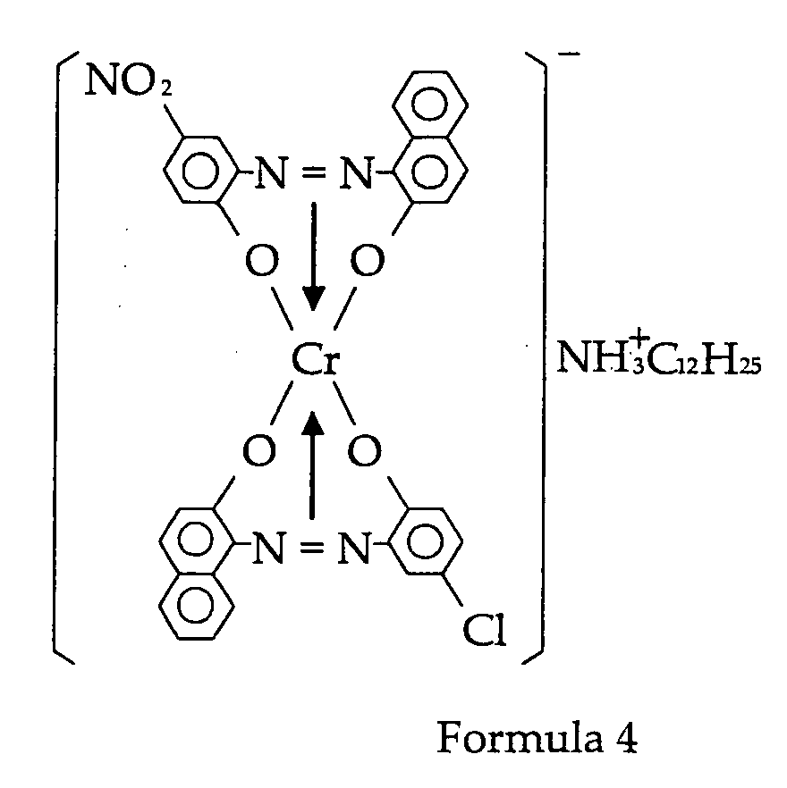
- Preferable examples of the complex compound are complex compounds expressed Formula 2 to Formula 6 as follow.
- any binder resin known in the art can be used.
- styrene resins homopolymers or copolymers containing styrene or styrene substitution products
- styrene resins such as styrene, poly- ⁇ -methyl styrene, styrene-chlorostyrene copolymer, styrene-propylene copolymer, styrene-butadiene copolymer, styrene-vinyl chloride copolymer, styrene-vinyl acetate copolymer, styrene-maleic acid copolymer, styrene-acrylic ester copolymer, styrene-methacrylic ester copolymer, styrene- ⁇ -chloromethyl acrylate copolymer and styrene-acrylonitrile
- Polyester resin is obtained by the condensation polymerisation of alcohol and carboxylic acid.
- examples of usable alcohols are glycols such as ethylene glycol, diethylene glycol, triethylene glycol and propylene glycol; etherified bisphenols such as 1, 4-bis(hydroxyl meta) cyclohexane and bisphenol A; bihydric alcohol monomers, trihydric or higher polyhydric alcohol monomers and the like.
- Examples of usable carboxylic acids are bivalent organic acid monomers such as maleic acid, fumaric acid, phthalic acid, isophthalic acid, terephthalic acid, succinic acid and malonic acid; trivalent or higher polyvalent carboxylic acid monomers such as 1, 2, 4-benzene tricarboxylic acid, 1,2,5-benzene tricarboxylic acid, 1,2,4-cyclohexane tricarboxylic acid, 1,2,4-naphthalene tricarboxylic acid, 1, 2, 5-hexane tricarboxylic acid, 1,3-dicarboxyl-2-methylene carboxypropane, and 1,2,7,8-octane tetra carboxylic acid; and the like.
- Glass transition temperature (Tg) of the polyester resin is preferably 58° C to 75° C.
- the above mentioned binder resins may be used singly, or in combination of two or more.
- a wax component in order to increase release properties during fixing, a wax component may also be used.
- examples are polyolefine waxes such as polypropylene wax and polyethylene wax; natural waxes such as candelila wax, rice wax and carnauba wax; and the like. It is preferred that the addition amount of the wax component is 0.5 parts by weight to 10 parts by weight, with respect to a binder resin of 100 parts by weight.
- a colourant can be suitably selected from any pigment known in the art depending on the intended purpose.
- the pigment are carbon black, lamp black, iron black, ultramarine blue, nigrosine dye, aniline blue, chalco oil blue, oil black, azo oil black and the like.
- the amount of the colourant used is 1 part by weight to 10 parts by weight, preferably 3 parts by weight to 7 parts by weight, with respect to a binder resin of 100 parts by weight.
- the toner may also contain other additives if necessary.
- additives are silica, alumina oxides, titanium oxides and the like.
- hydrophobically-treated silica, rutile particulate titanium oxide and the like having an average first-order particle diameter of 0.001 ⁇ m to 1 ⁇ m, preferably 0.005 ⁇ m to 0.1 ⁇ m, are suitable.
- surface-treated silica, titania with an organic silane and the like are suitable. These are generally used in a proportion of 0.1 % by weight to 5% by weight, preferably 0.2% by weight to 2% by weight. Developer
- the developer of the present invention contains the toner of the present invention.
- the developer of the present invention may be used as a single-component developer or a double-component developer, and the developer may further contain carrier in the case of the double-component developer.
- the developer of the present invention is an excellent agent for developing latent electrostatic images.
- Examples of the carrier used in admixture with the double-component developer of the present invention may be suitably selected from powder having particle diameter of the order of 30 ⁇ m to 1,000 ⁇ m with glass, iron, ferrite, nickel or zirconium as its principal component; a composite obtained by coating styrene-acrylic resin, silicon resin, polyamide resin or polyvinylidene fluoride resin on a core material of the powder and the like.
- the X-ray diffraction measurements according to the present invention were obtained for example using an instrument of RINT1100 manufactured by RIGAKU, CO. with the CuK ⁇ radiation as a X-ray source under the following conditions:
- the manufacturing process of the image forming toner and the developer has following steps.
- a first step is to mechanically mix the toner or developer component containing at least a binder resin, a main charge control agent and a pigment.
- the manufacturing process may also include a process in which powders other than particles, which become product in the crushing or grading steps, are recycled to be reused in the step of mechanical mixing and the step of melt kneading.
- the term “powders other than particles which become products (by-product)” refers to fine particles and coarse particles other than components which become products having a desired particle diameter obtained in the step of crushing after the step of melt kneading, and to fine particles and coarse particles other than components which become products having a desired particle diameter produced in the step of grading performed thereafter. It is preferred that, in the step of mixing or the step of melt kneading regarding to this by-product, the by-product is mixed with the raw material in a ratio of from 99 weight parts of other raw materials to 1 weight part of by-product, to 50 parts by weight of other raw materials to 50 parts by weight of by-product.
- the step of mechanically mixing the developer components comprising binder resins, a main charge control agent, pigments and by-products may be performed under the usual conditions in an ordinary mixing machine by means of rotating blades, there being no particular limitation.
- the melt kneading machine may be a single axis or double axis continuous kneader, or a batch kneader using a roll mill.
- melt kneading is performed under suitable conditions so as not to cause scission of the molecular chain of the binder resin.
- the melt kneading temperature should be determined according to the softening point of the binder resin. If it is too far below the softening point, scission of the molecular chain tends to severely occur, and if it is too high, dispersion tends to be depressed.
- the mixture is then crushed.
- this step of crushing it is preferred to first perform coarse crushing, and then fine crushing.
- the preferable method of crushing is crashed by impact against an impact plate in a jet air current, or mechanical crushing in the narrow gap between a rotating rotor and a stator.
- the crushed mixture is graded in an air current by centrifugation and the like, and a developer having a predetermined particle diameter, for example an average particle diameter of 5 ⁇ m to 20 ⁇ m, is thereby manufactured.
- inorganic fine particles such as the hydrophobically-treated silica powder mentioned earlier, may also be added to and mixed with the developer.
- This additive may be mixed using an ordinary powder mixer, preferably a powder mixer mounting a jacket or the like and capable of adjusting the internal temperature.
- it may be added in the middle of the process or gradually during the process.
- the rotation speed of the mixer, gyration speed, time and temperature may of course be varied. At first, a strong charge may be given followed by a relatively weak charge, or the reverse may be done.
- mixing devices include V-shaped mixer, rocking mixer, Redige mixer, Nauta mixer, Henschel mixer and the like.
- the process cartridge of the present invention contains an image developer which comprises the image forming toner or the developer of the present invention and supplies either the toner or the developer to a latent electrostatic image on a latent electrostatic image bearing member so as to develop the latent electrostatic image.
- the process cartridge of the present invention is formed in a one-piece component which is removable from an image-forming apparatus.
- image developer refers to a developing device which develop latent electrostatic images using the developer of the present invention so as to visualize the latent electrostatic images.
- FIG. 3 is an example of the construction of an image-forming process unit (process cartridge) 106, having a photoconductor drum 101 which functions as a latent electrostatic image bearing member, a charging roller 103 which functions as a charger, a cleaner 105 which functions as a cleaner and an image developer 102 which functions as an image developer.
- the image developer 102 has a developer sleeve 104.
- the charging roller 103 apply charge to the photoconductor drum 101, the charged photoconductor drum 101 forms a latent electrostatic image thereon after exposure, the image developer 102 supply the toner therein to the latent electrostatic image using the developer sleeve 104 so as to develop the latent electrostatic image, and then the cleaner 105 cleans the excess toner from the photoconductor drum 101 after transferring the developed image to a recording material and the like. All of these members are formed in a one-piece construction, which can be removed from an image-forming apparatus.
- the image-forming apparatus of the present invention contains a latent electrostatic image bearing member, a light irradiator which irradiate a light to the latent electrostatic image bearing member so as to form a latent electrostatic image, an image developer which contains and supply the image-forming toner of the present invention to the latent electrostatic bearing member so as to develop the latent electrostatic image.
- the image-forming apparatus may further contains a cleaner which removes and collect an excess image-forming toner from the latent electrostatic image bearing member, and a recycler which supplies the excess toner collected by the cleaner to the image developer so as to reuse the excess toner.
- the process cartridge and the image-forming apparatus of the present invention are able to attain high quality images with good granularity and no fogging, and maintain a charge of the toner even in the environment of a high temperature and high humidity.
- the image-forming process of the present invention contains a step of recycling, in which the surface of the latent electrostatic image bearing member is cleaned after transferring the toner image to the recording material, the excess toner remained on the latent electrostatic image bearing member is collected, and the excess toner is provided to the image developer so as to reuse in the step of developing.
- a charger in the step of charging, a charger is brought into contact with the latent electrostatic image bearing member, and an external voltage is applied to the charger in order to charge the latent electrostatic image bearing member.
- an latent electrostatic image on a latent electrostatic image bearing member is developed by the developer of the present invention, and in the step wherein the developed image is electrostatically transferred to a recording material by the transfer, the latent electrostatic image bearing member and transfer come into contact.
- the step of transferring may include a primary transfer which transfer the toner image to an intermediate transfer such as a belt, and a secondary transfer which transfer the toner image, for example, from the belt to the recording material.
- the cleaner comprises a cleaning blade.
- one or two of the rollers has elasticity.
- FIG. 1 An example of the image-forming process of the present invention will now be described referring to FIG. 1.
- the digital image-forming apparatus of FIG. 1 is provided with an internal drum-shaped photoconductor (latent electrostatic image bearing member) 1 using the electrophotographic method known in the art.
- a charger 2, a light irradiator 3, an image developer 4, a transfer 5, a cleaner 6, a recycler 15 and a fixer 10, are disposed in the rotation direction shown by the arrow A around the periphery of the drum-shaped photoconductor 1 so as to proceed the steps of the image-forming process in order.
- the light irradiator 3 forms a latent electrostatic image on the photoconductor 1 based on an image signal read by a reader 8 from a document placed on a document tray 7 on the upper surface of the digital image-forming apparatus.
- the latent electrostatic image formed on the photoconductor 1 is developed by toner by the image developer 4, and this toner image is electrostatically transferred by the transfer 5 to a recording material which is supplied from a paper supplier 9.
- the recording material carrying the toner image is transported to the fixer 10, fixed, and delivered outside the image-forming apparatus.
- parts of the photoconductor 1 to which non-transferred parts or dirt may be adhering are cleaned by a cleaning blade 6a and a brush roller or a rubber roller 6b of the cleaner 6, and the toner collected by cleaning is recovered to a toner hopper by the recycler 15, mixed with extra toner and then transferred to the developer container in the image developer 4 to be used in the following step of the image-forming process.
- the transfer is also cleaned by a transfer cleaning unit 11, and the excess toner on the transfer 5 was collected to recover.
- the toner for disposal is transferred to a disposal toner tank 14.
- toner sticks One way in which toner sticks is that the charge control agent which is present as aggregates on the toner surface sticks freely, and this then serves as a nucleus for further adhesion.
- the charge control agent has good dispersion in other materials. Therefore, there are no aggregates on the toner surface. As there are no nuclei for sticking, moreover, adhesion of toner does not occur in the step of charging, the step of transferring and the step of cleaning even though they are all contact steps.
- the material for the charging roller, charging blade, transfer belt and cleaning blade is preferably electroconductive rubber.
- the toner used in the image-forming process of the present invention has enhanced charging properties and a sharp charge distribution, and as its charge is very stable with respect to environmental changes such as high temperature and high humidity, a dense image can be uniformly formed on the recording material. Further, in the fixing step, one or two rollers have elasticity. It was found that, as a result, the contact between the toner image surface and the recording material is closer, there is little scatter of fixing properties and image density, not much unevenness of gloss, and as the image is not spoiled even after fixing, a clear image with very good granularity can be obtained.
- FIG. 2 shows an example of a fixer using the heat roller fixing method.
- the basic construction comprises a fixing roller 21 comprising a heater 24 such as a halogen lamp, and a pressure roller 25 having an elastic layer 27 made of expanded silicone rubber or the like on a core metal 26, which is pressed in contact with the fixing roller 21.
- a release layer 28 comprising PFA tube or the like is provided on the elastic layer 27 of the pressure roller 25.
- the fixing roller 21 has an elastic layer 22 of silicone rubber or the like on a core metal 33, a surface layer 23 of a fluorine resin or the like to prevent adhesion due to the viscosity of the toner.
- the thickness of the elastic layer 22 is of the order of 100 ⁇ m to 500 ⁇ m.
- the surface layer 23 comprises PFA tube or the like in the same way as the pressure roller 25, and from the viewpoint of functional deterioration, it preferred that the thickness thereof is in the range of 10 ⁇ m to 50 ⁇ m.
- a thermal detector 29 is installed on the outer peripheral surface of the fixing roller 21, and controls the heater 24 by thermal controller 32 so as to maintain the temperature effectively constant by detecting the surface temperature of the fixing roller 21. In the fixer having this construction, the fixing roller 21 and pressure roller 25 are brought into contact under a predetermined applied pressure to form a fixing nip part N.
- the rollers are then driven respectively in the directions R1, R5 by a driver, which is not showed in FIG.2, so that a recording material P is gripped and transported by the aforesaid fixing nip part N.
- the fixing roller 21 is controlled to the predetermined temperature by the heater 24, a toner image T on the recording material P is melted by heat under pressure when it passes between the two rollers, exits the two rollers, and is fixed to the recording material P as an indelible image by cooling.
- the pressure roller has an external diameter of 30 mm and a thickness of 6mm, it surface is covered by electroconductive PFA tube, and the rubber hardness on the axis is 42HS (Aska C).
- the fixing roller comprises an aluminium core, and its thickness "t" is 0.4mm. According to this construction, in order to obtain the nip N, a force of 88 newton (N) is applied on one side of the two ends of the rollers, the surface pressure at this time being 9.3 N/cm 2 .
- the X-ray diffraction measurement was performed on the obtained charge control agent using the instrument of RINT 1100 manufactured by RIGAKU CO. with the CuK ⁇ radiation as a X-ray source under the following conditions:
- This toner was mixed with a carrier formed of ferrite particles of average particle diameter 50 ⁇ m coated with silicone resin to give a 4.0% toner concentration so as to prepare a double-component developer.
- the double-component developer having a toner concentration of 4.0% was obtained by mixing the toner and the carrier formed of ferrite particles having an average particle diameter of 50 ⁇ m, coated with a silicone, under the high temperature and high humidity environment (30° C, 90% RH) and the ordinary temperature and ordinary humidity environment (25°C, 65% RH). Thereafter, the charge thereof was measured by KYOCERA CHEMICAL CORPORATION Blowoff Powder Charge Tester TB-200.
- the Ricoh Imagio 7050 incorporates a recycle system.
- the Ricoh Imagio 420 incorporates a recycle system.
- the method was identical to that of Examples 1 to 5, except that the fixing apparatus part of the Ricoh Imagio 7050 was modified so that the fixing apparatus comprising an elastic layer.
- a mixture was prepared by adding 110 g (0.59 mol) of chromium (III) formate to 600g ethyl cellosolve and 300g ethylene glycol, and stirred for 0.5 hours at 90°C. 445 g of a mono-azo compound was added to the mixture, the temperature thereof was raised up to 150 degrees and the mixture was stirred for 2.5 hours. This reaction solution was dispersed in 5000 ml of a 3% aqueous hydrochloric acid solution, stirred at 60 degrees for 0.5 hours, and filtered. The filtrate was rinsed with warm water and dried to give 380g of a violet powder.
- Comparative Example 1 the charging roller was soiled, and there was a large amount of fogging of the image surrounding the soiled part. In Comparative Example 5, both ends of the transfer belt were soiled.
- the toner and the image-forming method of the present invention there is no decrease of charge in high temperature, high humidity environments, and even when the charge of the carrier is low, an image with no fogging and good granularity can be obtained. Even in a recycle system, an excellent image with no fogging due to impaired charge appearance in the reused toner and good granularity can be obtained.
Landscapes
- Physics & Mathematics (AREA)
- General Physics & Mathematics (AREA)
- Developing Agents For Electrophotography (AREA)
Abstract
The present invention provides an image-forming toner having no
charge-decrease at high temperature and humidity, an excellent
image with no fogging and good granularity, and high transfer
efficiency even with a low-charged carrier. The image-forming
toner contains a binder resin, a colorant and a charge control agent
comprising a complex compound represented by Formula 1:
 wherein X represents a hydrogen atom, lower alkyl group, nitro
group or halogen group and may be identical or different, A+
represents a hydrogen ion, sodium ion, potassium ion, ammonium
ion or aliphatic ammonium ion;
wherein X represents a hydrogen atom, lower alkyl group, nitro
group or halogen group and may be identical or different, A+
represents a hydrogen ion, sodium ion, potassium ion, ammonium
ion or aliphatic ammonium ion;
wherein, in X-ray diffraction of the charge control agent using CuKα radiation as a X-ray source, the measurement angle 2 is within a range of 5 degrees to 30 degrees, the main peak of the Bragg angle 2 is a Main Peak A at 8.6±0.3 degrees, and the X ray intensity of the main peak is within a range of 8000 cps to 15,000 cps at a scanning speed of 0.5 degrees /min to 4 degrees/min.
wherein, in X-ray diffraction of the charge control agent using CuKα radiation as a X-ray source, the measurement angle 2 is within a range of 5 degrees to 30 degrees, the main peak of the Bragg angle 2 is a Main Peak A at 8.6±0.3 degrees, and the X ray intensity of the main peak is within a range of 8000 cps to 15,000 cps at a scanning speed of 0.5 degrees /min to 4 degrees/min.
Description
- The present invention relates to an image-forming process in electrophotography, an image-forming toner therefore, a developer containing the same, a process cartridge containing the same and an image-forming apparatus containing the same.
- Various types of electrophotographic methods are known in the art. Developing methods used therein may broadly be classified as a dry developing method and a wet developing method, and dry developers in the dry developing method may be further classified as a single-component developer and a double-component developer. In both methods, the toner must have either a positive or negative charge depending on a polarity of a latent electrostatic image to be developed, and it is most effective to add a charge control agent in order to retain the charge in the toner.
- Although there are various types of charge control agents available, chromium complexes have been conventionally used due to their cost efficiency and negative charging properties. In Japanese Patent Application Laid-Open (JP-A) No. 2000-321819, a toner is proposed containing a chromium complex and a polyester resin having an acid value of 15 mg KOH/g to 30 mg KOH/g, and the predominance of negative charge properties is thereby improved. However, polyester resins generally have the defect that their properties become varied affected by environmental changes. Although there is no problem immediately after the toner is manufactured, the toner deteriorates with time. If the deteriorated toner is left in a high humidity atmosphere, moreover, the charge amount thereof sharply decreases.
- In Japanese Patent (JP-B) No. 2837678, a toner is proposed containing a metal salt of salicylic acid and a chromium-containing azo dye, and this permits a stable negative charging property even during long periods of continuous use without the occurrence of filming. However, due to the heat and shear energy of the step of kneading during toner manufacturing process, the structure of the toner changes by releasing salicylic acid, so conditions of the toner manufacturing process must be strictly controlled in order to obtain the desired quality.
- In recent years, as a method of recovering toner by a cleaner, a recycle system has been disclosed. In the recycle system, a transport path is provided for transporting a recovered toner from the cleaner to an image developer, and this is used as a part of a supplementary toner supplied to the image developer. However, if the recycle system is used, toner charging properties considerably deteriorate due to electrical stress in the charger and the like, and the toner deposition on the background of images or the toner scattering tends to occur due to the poorer toner charge. To resolve this problem, in JP-A No. 2001-13731, a copolymer containing a quaternary ammonium salt is included in a toner, molecular weight and viscosity of the quaternary ammonium salt-containing copolymer being specified. As a result, charging properties are improved, but degradation of heat resistance in storage or filming. occurs due to the inclusion of the low molecular weight, quaternary ammonium salt-containing copolymer.
- JP-A No. 06-59501 provides a toner suitable for recycling by specifying the toner particle distribution. In this way, the toner no longer generates rough particles and extremely fine particles due to the recycling system. However, the charging properties of the recycled toner were not necessarily improved, and several problems to be solved were still remained such as toner deposition on a developing sleeve or toner deposition on a photoconductor caused by long periods of use.
- In general, a heat roller fixing method is regarded as an extremely heating efficient fixing method since a toner image and a heat roller are in direct contact with each other. Moreover, the heat roller fixing method is widely used due to an advantage that an apparatus thereof can also be made compact. In the heat roller fixing method, however, an image quality is largely affected by a toner image formed on a transfer paper as the toner image is in direct contact with the transfer paper. Therefore, it is important to form a uniform toner image on the transfer paper. To achieve this object, various studies have been performed in the related art. For example, JP-A No. 06-230602 proposes a magnetic toner having the ratio of the toner image before and after fixing being controlled within a specified range. JP-A No. 08-220793 proposes a toner having voids in the toner particles being within a specified range when measured in a certain measurement cell. JP-A No. 08-278659 proposes a toner having a specified particle diameter distribution in which voids calculated from tap density is within a specified range. JP-A No. 10-48874 proposes a toner comprising an inorganic powder containing a silicon compound, having a specified particle diameter distribution, and in which voids calculated from tap density are within a specified range. Although they are effective methods for the first image, the toner may particularly deteriorate with time, or the toner charge may fall at high temperature and high humidity. In this situation, the charge distribution of the toner is broadened, and a dense toner image cannot be formed uniformly on the transfer paper.
- Also, in the heat roller fixing method, a very large amount of heat energy is taken up by the transfer paper because the toner image and the transfer paper are in direct contact. As a result, a surface temperature of the fixing roller considerably fluctuates depending on the usage mode, the type of recording material and environmental conditions, so that the image quality after fixing varies:
- If the surface temperature of the fixing roller is sufficiently high, there is no particular problem regarding fixing properties. However the melt viscosity of the binder resin in the toner falls and the toner image spreads out on the transfer paper after passing through the fixing roller. As a result, the reproducibility of fine lines deteriorates, and image quality is poor. Conversely, if the surface temperature of the fixing roller is low, the melt viscosity of the binder resin in the toner is high. Consequently the toner image does not spread out on the transfer paper after passing through the roller. In this case, however, fixing properties are poor.
- In order to resolve these problems, various techniques have been proposed in the related art.
- For example, Japanese Patent (JP-B) No. 2743476 proposes a heat roller fixing toner which contains core particles comprising a polyester resin and a wax containing polar groups, in which the core particles are covered by the binder resin and the melt viscosity of the polyester resin and the wax is specified. JP-A No. 03-122661, JP-A No. 04-85550 and Japanese Patent Application Publication (JP-B) No. 08-16804 describe a film-fixing capsule toner comprising a specific polyester resin and release agent in which the melt viscosity of the polyester resin at 80°C to 120°C, the slope of a graph showing the relation between the melt viscosity and temperature, and the melt viscosity of the release agent, are specified. Japanese Patent Application Publication (JP-B) No. 07-82250 proposes a film-fixing toner comprising a specific polyester resin, an organometallic compound and a release agent in which the melt viscosity of the polyester resin at 120°C to 150°C, the slope of a graph showing the relation between the melt viscosity and temperature, and the melt viscosity of the release agent, are specified. JP-B No. 07-72809 proposes a toner comprising a styrene-acrylic resin in which a relation between the melt viscosity measured at 110°C to 130°C and temperature, is specified. JP-A No. 10-246989 proposes a toner comprising a specific charge control agent, in which the average viscosity gradient is specified. Although these conventional techniques are effective in improving fixing properties, they did not consider improvement of image quality such as volume changes or surface area changes of the toner image.
- In recent years, with the trend towards increasingly high-quality images, toner particles are becoming finer. When the toner particles are fine, it is difficult to apply pressure to the toner particles even between the fixing rollers, so it is difficult to fix the toner image uniformly. This tendency becomes particularly obvious in case that a surface pressure of a fixing apparatus is low. Further, if a thin paper is used as a transfer paper, the surface pressure drops and toner image surface properties become poorer, which causes the image quality to decline. Also, if a thick paper is used as a transfer paper, the surface pressure increases, the toner is crushed and unevenness of the image is emphasized, again causing the image quality to decline. This phenomenon is particularly obvious in the case of digital developing, when the reproducibility of separate dots is considerably affected. In the heat roller fixing method utilising one or two rollers having an elastic layer, the heating efficiency is higher than in the other heat fixing methods, so this method is now widely used.
- Moreover, the half-tone density should be uniform. If microscopic density unevenness occur, the image will have a grainy appearance when being viewed with the naked eye. The physical evaluation value of this graininess is the granularity.
- Noise is measured by the Wiener spectrum, which should be the frequency characteristic of the density fluctuation.
- When the density fluctuation component having an average value of 0 is f (x), it may be expressed by:
- The granularity (GS) is a value obtained by integrating the product of "WS" and a Visual Transfer Function (VTF), and is expressed by the following equation:
- There is a high correlation between granularity and the subjective evaluation of image smoothness. The image becomes smoother as the value of the granularity is smaller, and the image becomes rougher and of poorer quality as the value of the granularity is larger:
- An object of the present invention is to provide an image-forming toner, a process cartridge having the same, an image-forming apparatus having the same and an imaging forming process applying the same, which permit an excellent image with no fogging and good granularity to be obtained, without decline of a charge of the toner even in the environment of a high temperature and high humidity.
- Another object of the present invention is to provide an image-forming toner, a process cartridge having the same, an image-forming apparatus having the same and an image-forming process applying the same, which permit an excellent image with no fogging and good granularity to be obtained without broadening the charge distribution of the developer even when a charge of a carrier is low, and which have a high transfer efficiency.
- Another object of the present invention is to provide an image-forming toner, which shows no structural changes of the charge control agent due to heat or shear energy in the step of kneading during the manufacturing process, and which permits a high degree of freedom of manufacturing conditions.
- Another object of the present invention is to provide an image-forming toner, process cartridge having the same, an image-forming apparatus having the same and an image-forming process applying the same, which permit an excellent image with good granularity to be obtained without fogging due to poorer charging of recycled toner in the recycling system.
- Another object of the present invention is to provide an image-forming toner, process cartridge having the same, an image-forming apparatus having the same and an image-forming process applying the same, in which the considerable spread of the toner image on a recording material such as a transfer paper after passing through the rollers in the fixing step, is suppressed, and which permit an excellent image with good granularity to be obtained.
- The image-forming toner of the present invention contains a binder resin, a colourant and a charge control agent, wherein the charge control agent comprises a complex compound expressed by
Formula 1, and in the X-ray diffraction of the charge control agent using CuKα radiation as a X-ray source, the measurement angle is within a range of 5 degrees to 30 degrees, the main peak of the Bragg angle 2 is a peak A at 8.6±0.3 degrees, and the X-ray intensity is within a range of 8000cps to 15000 cps at a scanning speed of 0.5 degrees/min to 4 degrees/min.
- In
Formula 1, "X"s express hydrogen atoms, lower alkyl groups, nitro groups or halogen groups and may respectively be identical or different, "A+" expresses a hydrogen ion, a sodium ion, a potassium ion, an ammonium ion or an aliphatic ammonium ion. - The developer of the present invention contains the image-forming toner of the present invention.
- The process cartridge of the present invention contains an image developer which comprises an image-forming toner of the present invention and supply the image-forming toner to a latent electrostatic image on a latent electrostatic image bearing member so as to develop the latent electrostatic image. In addition, the process cartridge is attachable to and detachable from an image-forming apparatus.
- The image-forming apparatus of the present invention contains a latent electrostatic image bearing member, a light irradiator which irradiate a light to the latent electrostatic image bearing member so as to form a latent electrostatic image, and an image developer which comprises an image-forming toner of the present invention and supply the image-forming toner to the latent electrostatic image bearing member so as to develop the latent electrostatic image.
- The image-forming process of the present invention contains a step of externally applying a voltage to a charger to charge a latent electrostatic image bearing member, a step of forming an electrostatic image on the latent electrostatic image bearing member which is charged, a step of developing the latent electrostatic image by the image-forming toner of the present invention so as to form a toner image, a step of transferring the toner image onto a recording material by externally applying a voltage, a step of cleaning the surface of the latent electrostatic image bearing member after the step of transferring by a cleaner, and a step of fixing the toner image on a recording material by passing the recording material between two rollers.
- FIG.1 is a schematic diagram showing an example of a digital copier.
- FIG. 2 is a schematic diagram showing an example of a fixing apparatus according to the heating roller method.
- FIG. 3 is a schematic diagram showing an example of a process cartridge.
- The image-forming toner of the present invention contains a binder resin, a colourant and a charge control agent comprising a complex compound expressed by
Formula 1.
- In the
Formula 1, "X"s express hydrogen atoms, lower alkyl groups, nitro groups or halogen groups and they may respectively be identical or different, "A+" expresses a hydrogen ion, a sodium ion, a potassium ion, an ammonium ion or an aliphatic ammonium ion. - The lower alkyl groups are alkyl groups having carbon atoms of 1 to 20, and preferable examples are C4H9, C12H25 and the like.
- The ammonium ion is either liner alkyl ammonium having carbon atoms of 8 to 16 or branched alkyl ammonium having carbon atoms of 8 to 16 which allows insertion of hetero atoms. Examples of the hetero atoms include nitrogen atom, oxygen atom, sulphur atom and the like. Of these, oxygen atom is preferable. Examples of the branched alkyl ammonium having carbon atoms of 8 to 16 with intermission of the hetero atoms may include NH3C3H6OC(C2H5)H C4H9, NH3C3H6OCH2C(C2H5)H C4H9 and the like.
- The image-forming toner of the present invention comprises the complex compound expressed by
Formula 1 as mentioned above and a crystalline plane thereof grows on the same plane. In X-ray diffraction of the crystalline plane using CuKα radiation as a X-ray source, the measurement angle is within a range of about 5 degrees to about 30 degrees, the main peak of the Bragg angle 2 is Main Peak A at 8.6±0.3 degrees, and the X ray intensity is within a range of about 8000 cps to about 15,000 cps, preferably 10,000 cps to 15,000 cps, at a scanning speed of 0.5 degrees/min to 4 degrees/min. The charge control agent of the image-forming toner of the present invention is therefore able to attain the functions of being enhanced charging properties as described above, and a sharp charge distribution and a stable charge with respect to fluctuations of environmental conditions such as high temperature, high humidity and low temperature, low humidity. - In the image-forming toner according to the present invention, moreover, the main peak of the Bragg angle 2 of the charge control agent, when X-ray diffraction is measured using CuKα radiation as a X-ray source, is at Main Peak A at 8.6±0.3 degrees, and having the half-value width of the main peak of about 0.30 degrees or less. In this case, the half-value width of the main peak is preferably 0.20 degrees or less and more preferably 0.15 degrees or less is.
- In the image-forming toner according to the present invention, the main peak of the Bragg angle 2 of the charge control agent, when X-ray diffraction is measured using CuKα radiation as a X-ray source, contains Main Peak A at 8.6±0.3 degrees and Sub-Peak B at 7.9±0.3 degrees, and the intensity ratio of the Main Peak A and Sub-Peak B is such that the intensity of the Sub-Peak B is within a range of about 30 to about 60, preferably within a range of 40 to 50, when the intensity of the Main Peak A is 100.
- In general, in X-ray diffraction measurements of crystalline materials, a unique diffraction peak appears depending on the interval between crystal planes due to the Bragg's law. The diffraction intensity depends on the crystal state and crystallinity, and the hardness due to crystallisation also depends on the crystallinity with some extent. The 2 Peak A (Main Peak A): 8.6±0.3 degrees is the peak due to the main component of the chromium complex. If intensity thereof is less than about 8000 cps, crystalline properties are low, so chelate bonds in the chromium compound are easily cut due to the heat or shear energy of kneading during manufacture, and charging properties decline. In particular, charging properties decline considerably at high temperature and high humidity. If the intensity thereof is more than about 15000 cps, negative polarity increases and cohesive force increases, so dispersion in other materials is inadequate, and a sharp charge distribution cannot be obtained. Specifically, when the main peak of the Bragg angle 2 for CuKα radiation is Main Peak A at 8.6±0.3 degrees, and the X-ray intensity lies within the range of 8000 cps to 15000 cps at a scanning speed of 0.5 degrees/min to 4 degrees/min, the charge appears rapidly, and a high charge, sharp charge distribution and good dispersion can be obtained. Further, if the half-value width of this peak is 0.30 degrees or less, charging properties are even sharper and stable even with environmental changes. Since the half-value width of the peak is related to homogeneity of the crystal state, crystalline homogeneity is enhanced when the half-value width of the peak is at 0.30 degrees or less.
- Moreover, the main peak of the Bragg angle 2 of the charge control agent, in the X-ray diffraction using CuKα radiation as a X-ray source, contains Main Peak A: 8.6±0.3 degrees and Sub-Peak B: 7.9±0.3 degrees, and the intensity ratio of the Main Peak A and the Sub-Peak B is such that the intensity of the Sub-Peak B lies within a range of 30 to 60 when the intensity of the Main Peak A is 100, so that the charge appears rapidly and a sharp charge distribution is obtained. In one single crystal face, there are equivalent planes. The number of equivalent lattice faces belonging to the shape of a given plane is referred to as the multiplicity of the plane, and these lattice faces have equal plane intervals. In the crystals of the chromium complex compound of the present invention, corresponding to the Main Peak A and the Sub-Peak B, the Main Peak A: 8.6+0.3 degrees is equivalent to an inter-plane interval of 9.927Å to 10.634Å, and the Sub Peak B: 7.9±0.3 degrees is equivalent to an inter-plane interval of 10.773 Å to 11.622 Å. It was found that crystals which grew on this inter-plane interval showed very good charging properties. When the intensity of the Sub-Peak B was 30 to 60 with respect of the intensity of the Main Peak A was 100, the most rapid charging and sharpest charge distribution are obtained.
- The toner having these characteristics has enhanced charging properties and a sharp charge distribution, and very good charge stability with respect to environmental changes at high temperature and high humidity. Therefore, a sharp toner charge distribution is obtained so that an image with good granularity and no fogging can be obtained with high transfer efficiency especially when a toner having these characteristics is used in such an image forming process as follow. The image forming process comprises the step of charging a latent electrostatic image bearing member by externally applying voltage, the step of forming a latent electrostatic image on the charged latent electrostatic image bearing member, the step of developing the latent electrostatic image by a toner so as to form a toner image, the step of transferring the toner image to a recording material through a transfer by externally applying a voltage to the transfer, the step of cleaning the surface of the latent electrostatic image bearing member by a cleaner after the step of transferring and the step of fixing the toner image on the recording material by passing the recording material between a pair of fixing rollers. In particular, the fact that the transfer efficiency is high and toner transfer residues are small and the fact that charging is rapid, show that this method is very well-suited to recycling systems and images of good granularity can be obtained over a long period of time.
- The charge control agent of the present invention is not particularly limited as long as it comprises a complex compound expressed by
Formula 1. Preferable examples of the complex compound are complex compounds expressed Formula 2 toFormula 6 as follow.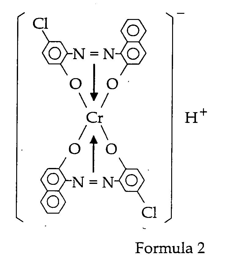



- As the binder resin used for the image-forming toner of the present invention, any binder resin known in the art can be used. Examples are styrene resins (homopolymers or copolymers containing styrene or styrene substitution products) such as styrene, poly-α-methyl styrene, styrene-chlorostyrene copolymer, styrene-propylene copolymer, styrene-butadiene copolymer, styrene-vinyl chloride copolymer, styrene-vinyl acetate copolymer, styrene-maleic acid copolymer, styrene-acrylic ester copolymer, styrene-methacrylic ester copolymer, styrene-α-chloromethyl acrylate copolymer and styrene-acrylonitrile-acrylic ester copolymer; polyester resin, epoxy resin, vinyl chloride resin, rosin modified maleic resin, phenol resin, polyethylene resin, polypropylene resin, petroleum resin, polyurethane resin, ketone resin, ethylene-ethyl acrylate copolymer, xylene resin, and polyvinyl butyrate resin. Of these, polyester resin is particularly preferred.
- Polyester resin is obtained by the condensation polymerisation of alcohol and carboxylic acid. Examples of usable alcohols are glycols such as ethylene glycol, diethylene glycol, triethylene glycol and propylene glycol; etherified bisphenols such as 1, 4-bis(hydroxyl meta) cyclohexane and bisphenol A; bihydric alcohol monomers, trihydric or higher polyhydric alcohol monomers and the like. Examples of usable carboxylic acids are bivalent organic acid monomers such as maleic acid, fumaric acid, phthalic acid, isophthalic acid, terephthalic acid, succinic acid and malonic acid; trivalent or higher polyvalent carboxylic acid monomers such as 1, 2, 4-benzene tricarboxylic acid, 1,2,5-benzene tricarboxylic acid, 1,2,4-cyclohexane tricarboxylic acid, 1,2,4-naphthalene tricarboxylic acid, 1, 2, 5-hexane tricarboxylic acid, 1,3-dicarboxyl-2-methylene carboxypropane, and 1,2,7,8-octane tetra carboxylic acid; and the like. Glass transition temperature (Tg) of the polyester resin is preferably 58° C to 75° C. The above mentioned binder resins may be used singly, or in combination of two or more.
- There is no particular limitation on the manufacturing process of these resins, and any of block polymerisation, solution . polymerisation, emulsion polymerisation and suspension polymerisation can be suitably used.
- In the present invention, in order to increase release properties during fixing, a wax component may also be used. Examples are polyolefine waxes such as polypropylene wax and polyethylene wax; natural waxes such as candelila wax, rice wax and carnauba wax; and the like. It is preferred that the addition amount of the wax component is 0.5 parts by weight to 10 parts by weight, with respect to a binder resin of 100 parts by weight.
- There is no limitation on a colourant and can be suitably selected from any pigment known in the art depending on the intended purpose. Examples of the pigment are carbon black, lamp black, iron black, ultramarine blue, nigrosine dye, aniline blue, chalco oil blue, oil black, azo oil black and the like. The amount of the colourant used is 1 part by weight to 10 parts by weight, preferably 3 parts by weight to 7 parts by weight, with respect to a binder resin of 100 parts by weight.
- The toner may also contain other additives if necessary. Examples of these additives are silica, alumina oxides, titanium oxides and the like. When it is desired to enhance high fluidity, hydrophobically-treated silica, rutile particulate titanium oxide and the like, having an average first-order particle diameter of 0.001µm to 1µm, preferably 0.005µm to 0.1µm, are suitable. Moreover surface-treated silica, titania with an organic silane and the like are suitable. These are generally used in a proportion of 0.1 % by weight to 5% by weight, preferably 0.2% by weight to 2% by weight. Developer
- The developer of the present invention contains the toner of the present invention. The developer of the present invention may be used as a single-component developer or a double-component developer, and the developer may further contain carrier in the case of the double-component developer. The developer of the present invention is an excellent agent for developing latent electrostatic images.
- Examples of the carrier used in admixture with the double-component developer of the present invention may be suitably selected from powder having particle diameter of the order of 30µm to 1,000µm with glass, iron, ferrite, nickel or zirconium as its principal component; a composite obtained by coating styrene-acrylic resin, silicon resin, polyamide resin or polyvinylidene fluoride resin on a core material of the powder and the like.
- The X-ray diffraction measurement method will now be described.
- The X-ray diffraction measurements according to the present invention were obtained for example using an instrument of RINT1100 manufactured by RIGAKU, CO. with the CuKα radiation as a X-ray source under the following conditions:
- X-ray tube: Cu
- Tube voltage: 50KV
- Tube current: 30MA
- Scanning speed: 2 degrees /min
-
- The manufacturing process of the image forming toner and the developer has following steps. A first step is to mechanically mix the toner or developer component containing at least a binder resin, a main charge control agent and a pigment. Thereafter, there are a step of melt kneading, a step of crushing and a step of grading. The manufacturing process may also include a process in which powders other than particles, which become product in the crushing or grading steps, are recycled to be reused in the step of mechanical mixing and the step of melt kneading.
- Herein, the term "powders other than particles which become products (by-product)" refers to fine particles and coarse particles other than components which become products having a desired particle diameter obtained in the step of crushing after the step of melt kneading, and to fine particles and coarse particles other than components which become products having a desired particle diameter produced in the step of grading performed thereafter. It is preferred that, in the step of mixing or the step of melt kneading regarding to this by-product, the by-product is mixed with the raw material in a ratio of from 99 weight parts of other raw materials to 1 weight part of by-product, to 50 parts by weight of other raw materials to 50 parts by weight of by-product.
- The step of mechanically mixing the developer components comprising binder resins, a main charge control agent, pigments and by-products, may be performed under the usual conditions in an ordinary mixing machine by means of rotating blades, there being no particular limitation.
- When the aforesaid step of mixing is complete, the mixture is then introduced into a kneading machine for melt kneading. The melt kneading machine may be a single axis or double axis continuous kneader, or a batch kneader using a roll mill.
- It is important that this melt kneading is performed under suitable conditions so as not to cause scission of the molecular chain of the binder resin. Specifically, the melt kneading temperature should be determined according to the softening point of the binder resin. If it is too far below the softening point, scission of the molecular chain tends to severely occur, and if it is too high, dispersion tends to be depressed.
- When the aforesaid step of melt kneading is complete, the mixture is then crushed. In this step of crushing, it is preferred to first perform coarse crushing, and then fine crushing. The preferable method of crushing is crashed by impact against an impact plate in a jet air current, or mechanical crushing in the narrow gap between a rotating rotor and a stator.
- After the step of crushing is complete, the crushed mixture is graded in an air current by centrifugation and the like, and a developer having a predetermined particle diameter, for example an average particle diameter of 5µm to 20µm, is thereby manufactured.
- When the developer is prepared, in order to enhance the fluidity, storage properties, developing properties and transfer properties of the developer, inorganic fine particles such as the hydrophobically-treated silica powder mentioned earlier, may also be added to and mixed with the developer. This additive may be mixed using an ordinary powder mixer, preferably a powder mixer mounting a jacket or the like and capable of adjusting the internal temperature. In order to modify the negative charging state given to the additive, it may be added in the middle of the process or gradually during the process. The rotation speed of the mixer, gyration speed, time and temperature may of course be varied. At first, a strong charge may be given followed by a relatively weak charge, or the reverse may be done.
- Preferable examples of mixing devices include V-shaped mixer, rocking mixer, Redige mixer, Nauta mixer, Henschel mixer and the like.
- The process cartridge of the present invention contains an image developer which comprises the image forming toner or the developer of the present invention and supplies either the toner or the developer to a latent electrostatic image on a latent electrostatic image bearing member so as to develop the latent electrostatic image. In addition, the process cartridge of the present invention is formed in a one-piece component which is removable from an image-forming apparatus. In the present invention, the term "image developer" refers to a developing device which develop latent electrostatic images using the developer of the present invention so as to visualize the latent electrostatic images.
- FIG. 3 is an example of the construction of an image-forming process unit (process cartridge) 106, having a
photoconductor drum 101 which functions as a latent electrostatic image bearing member, a chargingroller 103 which functions as a charger, a cleaner 105 which functions as a cleaner and animage developer 102 which functions as an image developer. Theimage developer 102 has adeveloper sleeve 104. The chargingroller 103 apply charge to thephotoconductor drum 101, the chargedphotoconductor drum 101 forms a latent electrostatic image thereon after exposure, theimage developer 102 supply the toner therein to the latent electrostatic image using thedeveloper sleeve 104 so as to develop the latent electrostatic image, and then the cleaner 105 cleans the excess toner from thephotoconductor drum 101 after transferring the developed image to a recording material and the like. All of these members are formed in a one-piece construction, which can be removed from an image-forming apparatus. - The image-forming apparatus of the present invention contains a latent electrostatic image bearing member, a light irradiator which irradiate a light to the latent electrostatic image bearing member so as to form a latent electrostatic image, an image developer which contains and supply the image-forming toner of the present invention to the latent electrostatic bearing member so as to develop the latent electrostatic image. The image-forming apparatus may further contains a cleaner which removes and collect an excess image-forming toner from the latent electrostatic image bearing member, and a recycler which supplies the excess toner collected by the cleaner to the image developer so as to reuse the excess toner.
- By applying the image-forming toner of the present invention, the process cartridge and the image-forming apparatus of the present invention are able to attain high quality images with good granularity and no fogging, and maintain a charge of the toner even in the environment of a high temperature and high humidity. Image-forming process
- The image-forming process of the present invention contains a step of recycling, in which the surface of the latent electrostatic image bearing member is cleaned after transferring the toner image to the recording material, the excess toner remained on the latent electrostatic image bearing member is collected, and the excess toner is provided to the image developer so as to reuse in the step of developing.
- In the image-forming process of the present invention, in the step of charging, a charger is brought into contact with the latent electrostatic image bearing member, and an external voltage is applied to the charger in order to charge the latent electrostatic image bearing member.
- In the image-forming process of the present invention, an latent electrostatic image on a latent electrostatic image bearing member is developed by the developer of the present invention, and in the step wherein the developed image is electrostatically transferred to a recording material by the transfer, the latent electrostatic image bearing member and transfer come into contact. The step of transferring may include a primary transfer which transfer the toner image to an intermediate transfer such as a belt, and a secondary transfer which transfer the toner image, for example, from the belt to the recording material.
- In the image-forming process of the present invention, the cleaner comprises a cleaning blade.
- In the image-forming process of the present invention, in the step of heat roller fixing, one or two of the rollers has elasticity.
- An example of the image-forming process of the present invention will now be described referring to FIG. 1. The digital image-forming apparatus of FIG. 1 is provided with an internal drum-shaped photoconductor (latent electrostatic image bearing member) 1 using the electrophotographic method known in the art. A charger 2, a
light irradiator 3, animage developer 4, atransfer 5, acleaner 6, a recycler 15 and afixer 10, are disposed in the rotation direction shown by the arrow A around the periphery of the drum-shapedphotoconductor 1 so as to proceed the steps of the image-forming process in order. - The
light irradiator 3 forms a latent electrostatic image on thephotoconductor 1 based on an image signal read by areader 8 from a document placed on adocument tray 7 on the upper surface of the digital image-forming apparatus. - The latent electrostatic image formed on the
photoconductor 1 is developed by toner by theimage developer 4, and this toner image is electrostatically transferred by thetransfer 5 to a recording material which is supplied from apaper supplier 9. The recording material carrying the toner image is transported to thefixer 10, fixed, and delivered outside the image-forming apparatus. - At the same time, parts of the
photoconductor 1 to which non-transferred parts or dirt may be adhering, are cleaned by acleaning blade 6a and a brush roller or arubber roller 6b of thecleaner 6, and the toner collected by cleaning is recovered to a toner hopper by the recycler 15, mixed with extra toner and then transferred to the developer container in theimage developer 4 to be used in the following step of the image-forming process. In addition, the transfer is also cleaned by a transfer cleaning unit 11, and the excess toner on thetransfer 5 was collected to recover. In the means time, the toner for disposal is transferred to adisposal toner tank 14. - In recent years, to decrease the generation of ozone, contact methods are effectively being used in the step of charging, the step of transferring and the step of cleaning. This involves the use of a charge roller, a charge blade, a transfer belt (5a) and cleaning blade (6a). However, the disadvantage arises as the toner comes in direct contact with the
photoconductor 1, so the toner easily sticks thereon. On the contrary, the toner according to the present invention does not have this disadvantage and is therefore preferred. This is actually due to the fact that the charge distribution is sharp, so the production of oppositely charged toner is small, and as the transfer efficiency is high, there is little toner transfer residue. This also means the process is highly suitable for recycling systems. One way in which toner sticks is that the charge control agent which is present as aggregates on the toner surface sticks freely, and this then serves as a nucleus for further adhesion. In the toner according to the present invention, the charge control agent has good dispersion in other materials. Therefore, there are no aggregates on the toner surface. As there are no nuclei for sticking, moreover, adhesion of toner does not occur in the step of charging, the step of transferring and the step of cleaning even though they are all contact steps. - In the image-forming process of the present invention, the material for the charging roller, charging blade, transfer belt and cleaning blade is preferably electroconductive rubber.
- As the toner used in the image-forming process of the present invention has enhanced charging properties and a sharp charge distribution, and as its charge is very stable with respect to environmental changes such as high temperature and high humidity, a dense image can be uniformly formed on the recording material. Further, in the fixing step, one or two rollers have elasticity. It was found that, as a result, the contact between the toner image surface and the recording material is closer, there is little scatter of fixing properties and image density, not much unevenness of gloss, and as the image is not spoiled even after fixing, a clear image with very good granularity can be obtained.
- Next, the fixer, in which one or two rollers have elasticity, will be described in detail. FIG. 2 shows an example of a fixer using the heat roller fixing method. The basic construction comprises a fixing
roller 21 comprising aheater 24 such as a halogen lamp, and apressure roller 25 having anelastic layer 27 made of expanded silicone rubber or the like on acore metal 26, which is pressed in contact with the fixingroller 21. Arelease layer 28 comprising PFA tube or the like is provided on theelastic layer 27 of thepressure roller 25. The fixingroller 21 has anelastic layer 22 of silicone rubber or the like on acore metal 33, asurface layer 23 of a fluorine resin or the like to prevent adhesion due to the viscosity of the toner. From the viewpoint of image quality and heat transfer efficiency during fixing, it is generally preferred that the thickness of theelastic layer 22 is of the order of 100µm to 500µm. Also, thesurface layer 23 comprises PFA tube or the like in the same way as thepressure roller 25, and from the viewpoint of functional deterioration, it preferred that the thickness thereof is in the range of 10µm to 50µm. Athermal detector 29 is installed on the outer peripheral surface of the fixingroller 21, and controls theheater 24 bythermal controller 32 so as to maintain the temperature effectively constant by detecting the surface temperature of the fixingroller 21. In the fixer having this construction, the fixingroller 21 andpressure roller 25 are brought into contact under a predetermined applied pressure to form a fixing nip part N. The rollers are then driven respectively in the directions R1, R5 by a driver, which is not showed in FIG.2, so that a recording material P is gripped and transported by the aforesaid fixing nip part N. The fixingroller 21 is controlled to the predetermined temperature by theheater 24, a toner image T on the recording material P is melted by heat under pressure when it passes between the two rollers, exits the two rollers, and is fixed to the recording material P as an indelible image by cooling. - The pressure roller has an external diameter of 30 mm and a thickness of 6mm, it surface is covered by electroconductive PFA tube, and the rubber hardness on the axis is 42HS (Aska C). The fixing roller comprises an aluminium core, and its thickness "t" is 0.4mm. According to this construction, in order to obtain the nip N, a force of 88 newton (N) is applied on one side of the two ends of the rollers, the surface pressure at this time being 9.3 N/cm2.
- The present invention will now be described referring to specific examples, but it should be understood that the present invention is not to be construed as being limited in any way thereby.
-
- Styrene-n-butylacrylate copolymer;
parts by weight as shown in Table 1 - Polyester resin;
parts by weight as shown in Table 1 - Carbon black (MITSUBISHI CHEMICAL MEDIA CO.,Ltd. #44);
10 parts by weight - Carnuba wax;
5 parts by weight - Charge control agent described hereinafter;
2 parts by weight -
- A mixture obtained by adding 110g (0.59 mol) of chromium (III) formate to 800g of ethyl cellosolve and 420g of ethylene glycol, was stirred at 85 degrees for one hour. Thereafter, 445g of a mono-azo compound was added to the mixture, the temperature was raised up to 125 degrees, and stirred for 4 hours. This reaction mixture was dispersed in 5000 ml of 3% hydrochloric acid solution, stirred at 60 degrees for one hour, and then filtered. The precipitate obtained by the filtration was rinsed with warm water and dried to obtain 430g of a violet powder.
- The X-ray diffraction measurement was performed on the obtained charge control agent using the instrument of RINT 1100 manufactured by RIGAKU CO. with the CuKα radiation as a X-ray source under the following conditions:
- X-ray tube: Cu
- Tube voltage: 50KV
- Tube current: 30MA
- Scanning speed: 2 degrees/min
-
- The above ingredients were kneaded using a double axis extruder, crushed and graded to obtain the desired weight average particle diameter in Table 1-1 and Table 1-2. Subsequently, fine silica powder (R-972: manufactured by Client Japan) was mixed therewith using a Henschel mixer to obtain a toner.
- This toner was mixed with a carrier formed of ferrite particles of average particle diameter 50µm coated with silicone resin to give a 4.0% toner concentration so as to prepare a double-component developer.
- The double-component developer having a toner concentration of 4.0% was obtained by mixing the toner and the carrier formed of ferrite particles having an average particle diameter of 50µm, coated with a silicone, under the high temperature and high humidity environment (30° C, 90% RH) and the ordinary temperature and ordinary humidity environment (25°C, 65% RH). Thereafter, the charge thereof was measured by KYOCERA CHEMICAL CORPORATION Blowoff Powder Charge Tester TB-200.
- Images were evaluated using the image testing device described below. The charger and transfer for the copier used are shown in Table 1-1, and Table 1-2.
- A first copy, and then 50000 copies, were taken under the ordinary temperature and ordinary humidity environment (18°C to 27°C, 30% RH to 70% RH) using Ricoh Imagio 7050, and the charge of the developer and granularity of the image were measured. The Ricoh Imagio 7050 incorporates a recycle system.
- A first copy, and then 50000 copies, were taken under the ordinary temperature and ordinary humidity environment (18°C to 27°C, 30% RH to 70% RH) using a Ricoh Imagio 420, and the charge of the developer and granularity of the image were measured. The Ricoh Imagio 420 incorporates a recycle system.
- The method was identical to that of Examples 1 to 5, except that the fixing apparatus part of the Ricoh Imagio 7050 was modified so that the fixing apparatus comprising an elastic layer. Method of measuring granularity
- First, 5000 copies of a Ricoh Standard Print Test Chart sample were printed continuously using the tester of Examples 1 to 10. Subsequently, the machine was left on standby for one hour, 5000 further copies were printed continuously, and a sample image was obtained. Next, the gray scale (half-tone part) of print image dots was read at 1000dpi using a GenaScan 5000 scanner manufactured by DAINIPPON SCREEN MFG. CO., LTD., and image data was thereby obtained. The image data was converted into a density distribution, and the granularity was evaluated by equation C. The results are shown in Table 1-1 and Table 1-2.


-
- Styrene-n-butylacrylate copolymer;
parts by weight shown in Table 2 - Polyester resin;
parts by weight shown in Table 2 - Carbon black (MITSUBISHI CHEMICAL MEDIA CO.,Ltd., #44);
10 parts by weight - Carnuba wax;
5 parts by weight - Charge control agent described below;
2 parts by weight -
- A mixture was prepared by adding 110 g (0.59 mol) of chromium (III) formate to 600g ethyl cellosolve and 300g ethylene glycol, and stirred for 0.5 hours at 90°C. 445 g of a mono-azo compound was added to the mixture, the temperature thereof was raised up to 150 degrees and the mixture was stirred for 2.5 hours. This reaction solution was dispersed in 5000 ml of a 3% aqueous hydrochloric acid solution, stirred at 60 degrees for 0.5 hours, and filtered. The filtrate was rinsed with warm water and dried to give 380g of a violet powder.
- An evaluation was performed in an identical way to Example 9, and using an identical copier to that of Example 9. The results are shown in Table 2.
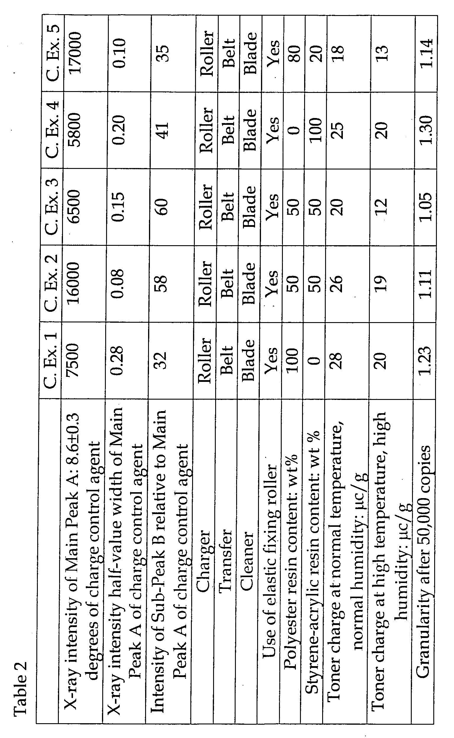
- In the above Examples 1 to 10, there was no adhesion or sticking of toner to the charging roller, transfer belt or cleaning blade.
- In Comparative Example 1, the charging roller was soiled, and there was a large amount of fogging of the image surrounding the soiled part. In Comparative Example 5, both ends of the transfer belt were soiled.
- According to the toner and the image-forming method of the present invention, there is no decrease of charge in high temperature, high humidity environments, and even when the charge of the carrier is low, an image with no fogging and good granularity can be obtained. Even in a recycle system, an excellent image with no fogging due to impaired charge appearance in the reused toner and good granularity can be obtained.
Claims (17)
- An image-forming toner comprising:wherein X represents a hydrogen atom, lower alkyl group, nitro group or halogen group and may be identical or different, A+ represents a hydrogen ion, sodium ion, potassium ion, ammonium ion or aliphatic ammonium ion;a binder resin;a colorant; anda charge control agent comprising a complex compound represented by Formula 1:

wherein, in X-ray diffraction of the charge control agent using CuKα radiation as a X-ray source, the measurement angle 2 is within a range of 5 degrees to 30 degrees, the main peak of the Bragg angle 2 is a Main Peak A at 8.6±0.3 degrees, and the X ray intensity of the main peak is within a range of 8000 cps to 15,000 cps at a scanning speed of 0.5 degrees /min to 4 degrees/min. - An image-forming toner according to Claim 1, wherein the X ray intensity of the main peak is within the range of 10,000 cps to 12,000 cps.
- An image-forming toner according to Claim 1 or Claim 2, wherein the main peak of the Bragg angle 2 is Main Peak A at 8.6±0.3 degrees, and the half-value width of the main peak is 0.30 degrees or less.
- An image-forming toner according to Claim 3, wherein the half-value width of the main peak is 0.20 degrees or less.
- An image-forming toner according to any one of Claims 1 to 4, wherein the main peak of the Bragg angle 2 contains Main Peak A at 8.6±0.3 degrees and Sub-Peak B at 7.9±0.3 degrees, and the intensity ratio of the Main Peak A and the Sub-Peak B is such that the intensity of the Sub-Peak B is within a range of 30 to 60 when the intensity of the Main Peak A is 100.
- An image-forming toner according to Claim 5, wherein the intensity ratio of the. Main Peak A and the Sub-Peak B is such that the intensity of the Sub-Peak B is within a range of 40 to 50 when the intensity of the Main Peak is 100.
- A developer containing the image-forming toner according to any one of Claims 1 to 6.
- A developer according to Claim 7, wherein the developer further contains a carrier.
- An image-forming apparatus comprising:a latent electrostatic image bearing member;a light irradiator configured to irradiate light to the latent electrostatic image member so as to form a latent electrostatic image; andan image developer configured to comprise an image-forming toner according to any one of Claims 1 to 6 and supply the image-forming toner to the latent electrostatic image bearing member so as to develop the latent electrostatic image.
- An image-forming apparatus according to Claim 9, wherein the image-forming apparatus further comprises:a cleaner configured to remove and collect an excess image-forming toner from the latent electrostatic image bearing member; anda recycler configured to supply the excess toner collected by the cleaner to the image developer so as to reuse the excess toner in the developing step.
- A process cartridge comprising:wherein the process cartridge is attachable to and detachable from an image-forming apparatus.an image developer comprising an image-forming toner according to any one of Claims 1 to 6 and configured to supply the image-forming toner to a latent electrostatic image on a latent electrostatic image bearing member so as to develop the latent electrostatic image;
- An image-forming process comprising the steps of:charging a latent electrostatic image bearing member by externally applying a voltage;forming an electrostatic image on the charged latent electrostatic image bearing member,developing the electrostatic image with the image-forming toner according to Claims 1 to 6 so as to form a toner image;transferring the toner image onto a recording material by means of a transfer by externally applying a voltage to the transfer;cleaning the surface of the latent electrostatic bearing member with a cleaner after the transfer step; andfixing the toner image on a recording material by passing the recording material between a pair of fixing rollers.
- An image-forming process according to Claim 12, which further comprises the steps of:cleaning the surface of the latent electrostatic image bearing member after the latent electrostatic image is transferred, collecting the excess image-forming toner thereon; andsupplying the excess image-forming toner to the image developer so as to reuse the excess image-forming toner.
- An image-forming process according to Claim 12 or Claim 13, wherein the step of charging is realised by bringing the charger into contact with the latent electrostatic image bearing member and externally applying a voltage to the charger so as to charge the latent electrostatic image bearing member.
- An image-forming process according to any one of Claims 12 to 14, wherein the steps of developing and transferring are realised by bringing the latent electrostatic image bearing member into contact with the transfer.
- An image-forming process according to any one of Claims 12 to 15, wherein the cleaner includes a cleaning blade.
- An image-forming process according to any one of Claims 12 to 16, wherein at least one of the fixing rollers has elasticity in the fixing step.
Applications Claiming Priority (2)
| Application Number | Priority Date | Filing Date | Title |
|---|---|---|---|
| JP2002053025A JP2003255617A (en) | 2002-02-28 | 2002-02-28 | Electrostatic latent image developing toner and image forming method |
| JP2002053025 | 2002-02-28 |
Publications (1)
| Publication Number | Publication Date |
|---|---|
| EP1341052A1 true EP1341052A1 (en) | 2003-09-03 |
Family
ID=27678541
Family Applications (1)
| Application Number | Title | Priority Date | Filing Date |
|---|---|---|---|
| EP03004506A Withdrawn EP1341052A1 (en) | 2002-02-28 | 2003-02-28 | Image-forming toner, developer, process cartridge and image-forming apparatus comprising the same and image-forming process |
Country Status (2)
| Country | Link |
|---|---|
| EP (1) | EP1341052A1 (en) |
| JP (1) | JP2003255617A (en) |
Cited By (1)
| Publication number | Priority date | Publication date | Assignee | Title |
|---|---|---|---|---|
| EP2078986A1 (en) * | 2008-01-09 | 2009-07-15 | Ricoh Company, Ltd. | Toner for developing electrostatic latent image, and image forming method using the toner |
Families Citing this family (1)
| Publication number | Priority date | Publication date | Assignee | Title |
|---|---|---|---|---|
| JP4680049B2 (en) * | 2005-11-02 | 2011-05-11 | 株式会社リコー | Toner for developing electrostatic image, developer and image forming method |
Citations (4)
| Publication number | Priority date | Publication date | Assignee | Title |
|---|---|---|---|---|
| EP0686882A1 (en) * | 1994-05-13 | 1995-12-13 | Canon Kabushiki Kaisha | Toner for developing electrostatic images, process cartridge, and image forming method |
| EP0967527A1 (en) * | 1998-06-24 | 1999-12-29 | Canon Kabushiki Kaisha | Toner and image forming method |
| EP1096325A2 (en) * | 1999-10-29 | 2001-05-02 | Canon Kabushiki Kaisha | Toner |
| JP2001350305A (en) * | 2000-06-02 | 2001-12-21 | Kyocera Mita Corp | Color image forming device |
-
2002
- 2002-02-28 JP JP2002053025A patent/JP2003255617A/en active Pending
-
2003
- 2003-02-28 EP EP03004506A patent/EP1341052A1/en not_active Withdrawn
Patent Citations (4)
| Publication number | Priority date | Publication date | Assignee | Title |
|---|---|---|---|---|
| EP0686882A1 (en) * | 1994-05-13 | 1995-12-13 | Canon Kabushiki Kaisha | Toner for developing electrostatic images, process cartridge, and image forming method |
| EP0967527A1 (en) * | 1998-06-24 | 1999-12-29 | Canon Kabushiki Kaisha | Toner and image forming method |
| EP1096325A2 (en) * | 1999-10-29 | 2001-05-02 | Canon Kabushiki Kaisha | Toner |
| JP2001350305A (en) * | 2000-06-02 | 2001-12-21 | Kyocera Mita Corp | Color image forming device |
Non-Patent Citations (1)
| Title |
|---|
| PATENT ABSTRACTS OF JAPAN vol. 2002, no. 04 4 August 2002 (2002-08-04) * |
Cited By (2)
| Publication number | Priority date | Publication date | Assignee | Title |
|---|---|---|---|---|
| EP2078986A1 (en) * | 2008-01-09 | 2009-07-15 | Ricoh Company, Ltd. | Toner for developing electrostatic latent image, and image forming method using the toner |
| US8202676B2 (en) | 2008-01-09 | 2012-06-19 | Ricoh Company, Limited | Toner for developing electrostatic latent image, and image forming method using the toner |
Also Published As
| Publication number | Publication date |
|---|---|
| JP2003255617A (en) | 2003-09-10 |
Similar Documents
| Publication | Publication Date | Title |
|---|---|---|
| US7150954B2 (en) | Image forming method and toner for use in the method | |
| JP5268504B2 (en) | Toner and image forming method | |
| US6964835B2 (en) | Toner and image forming method using the toner | |
| EP0843224B1 (en) | Toner for developing electrostatic image | |
| CN112782947B (en) | Carrier and developer for electronic photographic imaging, electronic photographic imaging method and device | |
| JP5398423B2 (en) | toner | |
| JP2010160229A (en) | Toner, image forming method, and image forming apparatus | |
| JP3132711B2 (en) | Toner composition for electrostatic charge development and image forming method | |
| EP1341052A1 (en) | Image-forming toner, developer, process cartridge and image-forming apparatus comprising the same and image-forming process | |
| JP4756885B2 (en) | Development device | |
| JP2001147585A (en) | Image forming method and apparatus | |
| JP4378210B2 (en) | Magnetic fine particle dispersed resin carrier and two-component developer | |
| JP4250486B2 (en) | Development method | |
| JP2986139B2 (en) | Magnetic developer | |
| JP4011779B2 (en) | Developing apparatus and image forming method | |
| JP2000330327A (en) | Electrophotographic developer and image forming method | |
| JP3897297B2 (en) | Image forming method | |
| JP3486471B2 (en) | Image forming method and toner | |
| JP2003270838A (en) | toner | |
| JP2001183869A (en) | Polymerized toner and method for producing the same | |
| JP2004117460A (en) | Image forming method | |
| JP2000214678A (en) | Image forming method and image forming apparatus | |
| JP2001100450A (en) | Electrophotographic toner and electrophotographic apparatus | |
| JP4030066B2 (en) | Electrophotographic developer and image forming method | |
| JP2003098720A (en) | Image forming method and toner used therefor |
Legal Events
| Date | Code | Title | Description |
|---|---|---|---|
| PUAI | Public reference made under article 153(3) epc to a published international application that has entered the european phase |
Free format text: ORIGINAL CODE: 0009012 |
|
| AK | Designated contracting states |
Kind code of ref document: A1 Designated state(s): AT BE BG CH CY CZ DE DK EE ES FI FR GB GR HU IE IT LI LU MC NL PT SE SI SK TR |
|
| AX | Request for extension of the european patent |
Extension state: AL LT LV MK RO |
|
| 17P | Request for examination filed |
Effective date: 20031015 |
|
| AKX | Designation fees paid |
Designated state(s): AT BE BG CH CY CZ DE DK EE ES FI FR GB GR HU IE IT LI LU MC NL PT SE SI SK TR |
|
| STAA | Information on the status of an ep patent application or granted ep patent |
Free format text: STATUS: THE APPLICATION IS DEEMED TO BE WITHDRAWN |
|
| 18D | Application deemed to be withdrawn |
Effective date: 20080429 |