EP1341001A2 - Monopulse radar system - Google Patents
Monopulse radar system Download PDFInfo
- Publication number
- EP1341001A2 EP1341001A2 EP02019077A EP02019077A EP1341001A2 EP 1341001 A2 EP1341001 A2 EP 1341001A2 EP 02019077 A EP02019077 A EP 02019077A EP 02019077 A EP02019077 A EP 02019077A EP 1341001 A2 EP1341001 A2 EP 1341001A2
- Authority
- EP
- European Patent Office
- Prior art keywords
- signal
- calibration
- radar system
- monopulse radar
- target
- Prior art date
- Legal status (The legal status is an assumption and is not a legal conclusion. Google has not performed a legal analysis and makes no representation as to the accuracy of the status listed.)
- Withdrawn
Links
Images







Classifications
-
- G—PHYSICS
- G01—MEASURING; TESTING
- G01S—RADIO DIRECTION-FINDING; RADIO NAVIGATION; DETERMINING DISTANCE OR VELOCITY BY USE OF RADIO WAVES; LOCATING OR PRESENCE-DETECTING BY USE OF THE REFLECTION OR RERADIATION OF RADIO WAVES; ANALOGOUS ARRANGEMENTS USING OTHER WAVES
- G01S7/00—Details of systems according to groups G01S13/00, G01S15/00, G01S17/00
- G01S7/02—Details of systems according to groups G01S13/00, G01S15/00, G01S17/00 of systems according to group G01S13/00
- G01S7/40—Means for monitoring or calibrating
- G01S7/4004—Means for monitoring or calibrating of parts of a radar system
- G01S7/4021—Means for monitoring or calibrating of parts of a radar system of receivers
-
- G—PHYSICS
- G01—MEASURING; TESTING
- G01S—RADIO DIRECTION-FINDING; RADIO NAVIGATION; DETERMINING DISTANCE OR VELOCITY BY USE OF RADIO WAVES; LOCATING OR PRESENCE-DETECTING BY USE OF THE REFLECTION OR RERADIATION OF RADIO WAVES; ANALOGOUS ARRANGEMENTS USING OTHER WAVES
- G01S13/00—Systems using the reflection or reradiation of radio waves, e.g. radar systems; Analogous systems using reflection or reradiation of waves whose nature or wavelength is irrelevant or unspecified
- G01S13/02—Systems using reflection of radio waves, e.g. primary radar systems; Analogous systems
- G01S13/06—Systems determining position data of a target
- G01S13/42—Simultaneous measurement of distance and other co-ordinates
- G01S13/44—Monopulse radar, i.e. simultaneous lobing
-
- G—PHYSICS
- G01—MEASURING; TESTING
- G01S—RADIO DIRECTION-FINDING; RADIO NAVIGATION; DETERMINING DISTANCE OR VELOCITY BY USE OF RADIO WAVES; LOCATING OR PRESENCE-DETECTING BY USE OF THE REFLECTION OR RERADIATION OF RADIO WAVES; ANALOGOUS ARRANGEMENTS USING OTHER WAVES
- G01S7/00—Details of systems according to groups G01S13/00, G01S15/00, G01S17/00
- G01S7/02—Details of systems according to groups G01S13/00, G01S15/00, G01S17/00 of systems according to group G01S13/00
- G01S7/03—Details of HF subsystems specially adapted therefor, e.g. common to transmitter and receiver
- G01S7/032—Constructional details for solid-state radar subsystems
-
- G—PHYSICS
- G01—MEASURING; TESTING
- G01S—RADIO DIRECTION-FINDING; RADIO NAVIGATION; DETERMINING DISTANCE OR VELOCITY BY USE OF RADIO WAVES; LOCATING OR PRESENCE-DETECTING BY USE OF THE REFLECTION OR RERADIATION OF RADIO WAVES; ANALOGOUS ARRANGEMENTS USING OTHER WAVES
- G01S7/00—Details of systems according to groups G01S13/00, G01S15/00, G01S17/00
- G01S7/02—Details of systems according to groups G01S13/00, G01S15/00, G01S17/00 of systems according to group G01S13/00
- G01S7/40—Means for monitoring or calibrating
- G01S7/4052—Means for monitoring or calibrating by simulation of echoes
-
- G—PHYSICS
- G01—MEASURING; TESTING
- G01S—RADIO DIRECTION-FINDING; RADIO NAVIGATION; DETERMINING DISTANCE OR VELOCITY BY USE OF RADIO WAVES; LOCATING OR PRESENCE-DETECTING BY USE OF THE REFLECTION OR RERADIATION OF RADIO WAVES; ANALOGOUS ARRANGEMENTS USING OTHER WAVES
- G01S7/00—Details of systems according to groups G01S13/00, G01S15/00, G01S17/00
- G01S7/02—Details of systems according to groups G01S13/00, G01S15/00, G01S17/00 of systems according to group G01S13/00
- G01S7/40—Means for monitoring or calibrating
- G01S7/4052—Means for monitoring or calibrating by simulation of echoes
- G01S7/406—Means for monitoring or calibrating by simulation of echoes using internally generated reference signals, e.g. via delay line, via RF or IF signal injection or via integrated reference reflector or transponder
- G01S7/4069—Means for monitoring or calibrating by simulation of echoes using internally generated reference signals, e.g. via delay line, via RF or IF signal injection or via integrated reference reflector or transponder involving a RF signal injection
-
- G—PHYSICS
- G01—MEASURING; TESTING
- G01S—RADIO DIRECTION-FINDING; RADIO NAVIGATION; DETERMINING DISTANCE OR VELOCITY BY USE OF RADIO WAVES; LOCATING OR PRESENCE-DETECTING BY USE OF THE REFLECTION OR RERADIATION OF RADIO WAVES; ANALOGOUS ARRANGEMENTS USING OTHER WAVES
- G01S13/00—Systems using the reflection or reradiation of radio waves, e.g. radar systems; Analogous systems using reflection or reradiation of waves whose nature or wavelength is irrelevant or unspecified
- G01S13/88—Radar or analogous systems specially adapted for specific applications
- G01S13/93—Radar or analogous systems specially adapted for specific applications for anti-collision purposes
- G01S13/931—Radar or analogous systems specially adapted for specific applications for anti-collision purposes of land vehicles
-
- G—PHYSICS
- G01—MEASURING; TESTING
- G01S—RADIO DIRECTION-FINDING; RADIO NAVIGATION; DETERMINING DISTANCE OR VELOCITY BY USE OF RADIO WAVES; LOCATING OR PRESENCE-DETECTING BY USE OF THE REFLECTION OR RERADIATION OF RADIO WAVES; ANALOGOUS ARRANGEMENTS USING OTHER WAVES
- G01S13/00—Systems using the reflection or reradiation of radio waves, e.g. radar systems; Analogous systems using reflection or reradiation of waves whose nature or wavelength is irrelevant or unspecified
- G01S13/88—Radar or analogous systems specially adapted for specific applications
- G01S13/93—Radar or analogous systems specially adapted for specific applications for anti-collision purposes
- G01S13/931—Radar or analogous systems specially adapted for specific applications for anti-collision purposes of land vehicles
- G01S2013/9325—Radar or analogous systems specially adapted for specific applications for anti-collision purposes of land vehicles for inter-vehicle distance regulation, e.g. navigating in platoons
-
- G—PHYSICS
- G01—MEASURING; TESTING
- G01S—RADIO DIRECTION-FINDING; RADIO NAVIGATION; DETERMINING DISTANCE OR VELOCITY BY USE OF RADIO WAVES; LOCATING OR PRESENCE-DETECTING BY USE OF THE REFLECTION OR RERADIATION OF RADIO WAVES; ANALOGOUS ARRANGEMENTS USING OTHER WAVES
- G01S7/00—Details of systems according to groups G01S13/00, G01S15/00, G01S17/00
- G01S7/02—Details of systems according to groups G01S13/00, G01S15/00, G01S17/00 of systems according to group G01S13/00
- G01S7/40—Means for monitoring or calibrating
- G01S7/4004—Means for monitoring or calibrating of parts of a radar system
- G01S7/4017—Means for monitoring or calibrating of parts of a radar system of HF systems
Definitions
- the present invention relates to a monopulse radar system, and more specifically to a monopulse radar system for radiating a signal from a transmitting antenna, and receiving a signal reflected by a target with a plurality of receiving antennas to thereby detect an angle of an existing position of the target.
- a monopulse system In a radar system, a monopulse system is known as one method of detecting an azimuth angle to a target.
- the monopulse system radiates a signal from a transmitting antenna and receives a signal reflected by a target through the use of two or more receiving antennas. At this time, information about the angle of the target to the radar system is obtained from the difference in amplitude or phase between the signals received by the individual antennas.
- phase monopulse one using the phase difference
- amplitude monopulse a radar system using a phase monopulse has been described in, for example, Japanese Patent Laid-Open No. H11(1999)-271433.
- a signal generated from a signal generator OSC1 is radiated or emitted from a transmitting antenna ANT1.
- the radiated signal is reflected by a target, which in turn is received by two receiving antennas ANT2 and ANT3.
- the received signals are converted into low frequency signals by mixers MIX1 and MIX2, followed by being subjected to signal analytic processing such as FFT (Fast Fourier Transform) in signal processing means P1.
- FFT Fast Fourier Transform
- the difference in phase between signals received by two antennas is determined.
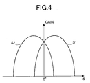
- directivity S1 of the receiving antenna ANT2 and directivity S2 of the receiving antenna ANT3 are distributed as represented in a gain characteristic of Fig. 4.
- a signal strength based on the sum of the signals received by the two antennas and a signal strength based on the difference between the signals are respectively represented as gain characteristics shown in Fig. 5.
- Further determining the ratio between the two from the sum signal and the difference signal results in a gain characteristic R1 of Fig. 6. The magnitude of this ratio and angles are associated with each other to thereby determine each corresponding angle.
- An in-vehicle radar system often makes use of an ultra-high frequency like a millimeter wave. Frequencies ranging from 76GHz to 77GHz are assigned to a vehicle radar used in a vehicle-to-vehicle distance warning system for a vehicle. In general, parts used in such an ultra-high frequency are expensive and large in part-to-parts characteristic variations as compared with parts used in a low frequency. Further, since the wave length is very short in the ultra-high frequency like the millimeter wave, variations in characteristic occur even upon assembly of modules for the radar system.
- the conventional monopulse radar system shown in Fig. 2 detects a phase difference or an amplitude difference from the low-frequency signals produced by the mixers MIX1 and MIX2 and calculates the azimuth angle of the target, based on it.
- a channel CH1 based on the receiving antenna ANT2 and a channel CH2 based on the receiving antenna ANT3 coincide in characteristic with each other with very high accuracy, or the difference therebetween in advance.
- a monopulse radar system of the present invention is provided with a calibration signal transmission line for supplying part of a transmit signal to each of respective receiving antennas or each of signal transmission lines (i.e., each of individual output parts of a plurality of receiving antennas) connected to the receiving antennas as a signal for calibration.
- the monopulse radar system is also provided with correcting means for calculating an azimuth angle of a pseudo target based on the calibration signal, determining an azimuth angle to be originally calculated by a monopulse radar, using the azimuth angle of the pseudo target, and adjusting at least either amplitude or phase so that the azimuth angle to be originally calculated and the azimuth angle of the pseudo target calculated precedently by each calibration signal coincide with each other.
- the signals for calibration respectively applied to the output parts of the plurality of receiving antennas are set as being equipower and equiphase.
- directivities of the two receiving antennas are made symmetrically with respect to a central direction, such a state that the signals are inputted to the respective antennas at equal power and in equiphase fashion in this way, occurs when a target is placed on a center line indicative of the center of an angle to be detected by a radar.
- a correcting process is performed in such a manner that the azimuth angle of the pseudo target, which is calculated from the signals for calibration, extends on the center line of the radar.
- the signal for calibration is used where the signal is always supplied to the output parts of the plurality of receiving antennas, and where a switch is provided on a calibration signal transmission line for supplying the signal calibration and a switch driving unit for controlling conducting and cut-off states of the switch is provided.
- a control on the conducting and cut-off states there are one for normally bringing the calibration signal transmission line to the cut-off state and bringing it to the conducting state upon calibration, and one for generating the conducting state of the switch periodically or with predetermined timing.
- a signal processing device such as a DSP is used to perform either one of the above-described calibrations automatically or with arbitrary timing, thereby correcting variations in characteristic developed after product shipment due to environmental variations, time variations in parts characteristic, etc.
- the accuracy of the angle detected by the monopulse radar can be maintained by ever-execution of the calibration.
- the correcting means of the monopulse radar comprises signal processing means for calculating an azimuth angle of a pseudo target, based on the signal for calibration, determining an azimuth angle to be originally calculated by the monopulse radar through the use of the azimuth angle of the pseudo target, determining correction data so that the azimuth angle to be originally calculated and the azimuth angle of the pseudo target, which is precedently detected by the signal for calibration, coincide with each other, writing the correction data into memory means, and correcting an azimuth angle of a target detected when actually activated as a radar, according to signal processing on the basis of the correction data stored in the memory means.
- the signal for calibration is modulated with a low frequency signal.
- the calibration signal is superimposed on a reflected signal, thus causing inconvenience. Namely, if the operation of an antenna is not perfectly stopped upon calibration, then a signal radiated from a transmitting antenna is reflected by an object present ahead of the antenna, which is then received by its corresponding receiving antenna depending on environments under which calibration is made.
- the present embodiment prevents such inconvenience that when a transmit signal is used as a signal for calibration as it is, this signal is superimposed on the calibration signal, so that accurate calibration cannot be performed.
- the present embodiment is also effective in preventing a low frequency signal converted by a mixer from being brought into a DC current in a homodyne type radar wherein the same ones are used for a local signal generator for generating a transmit signal and a signal generator for generating a local signal supplied to the mixer.
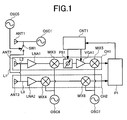
- Fig. 1 is a block diagram showing a configuration of a first embodiment of a monopulse radar system according to the present invention.
- the present embodiment is a monopulse radar system which has a transmitting antenna ANT1, and two receiving antennas ANT2 and ANT3 and which radiates or emits a transmit signal from the transmitting antenna ANT1, receives a signal obtained by allowing the transmit signal to be reflected by a target, with the receiving antennas ANT2 and ANT3, and detects an azimuth angle of its target according to signal processing.
- the monopulse radar system includes a signal transmission line L1 for calibration connected from an oscillator OSC1 to the transmitting antenna ANT1, from which part of the transmit signal is supplied to each of signal transmission lines L2 and L3 connected to the receiving antennas ANT2 and ANT3 as a signal for calibration, and a switch SW1 for bringing the signal transmission line L1 into conduction or a cut off state. Further, a channel CH1 for processing the signal received by one antenna ANT2 is provided with phase correcting means PS1 and amplitude correcting means VGA1.
- the switch SW1 is brought to a conducting state and at least one of the phase correcting means PS1 comprised of a variable phase shifter and the amplitude correcting means VAG1 comprised of a variable gain amplifier is adjusted so that an azimuth angle of a pseudo target, which is detected according to the signal for calibration, reaches a predetermined angle of a monopulse radar to thereby carry out an angle correction.
- the switch SW1 when the switch SW1 is brought into conduction, some of the transmit signal are supplied to the two receiving channels CH1 and CH2 via the signal transmission line L1 at equal power and in equiphase fashion. At this time, the switch SW1 is switched or changed over by a low frequency signal source OSC5 so that the signal for calibration is modulated with a low frequency.
- This signal is amplified by low noise amplifiers LNA1 and LNA2 for the respective channels CH1 and CH2. Thereafter, the amplified signals are mixed with a signal produced from an oscillator OSC6 by mixers MIX3 and MIX4 respectively, so that they are converted into signals each having an intermediate frequency.
- the signal having the intermediate frequency is allowed to pass through the variable phase shifter PS1 and the variable gain amplifier VGA1 in one channel CH1 and then mixed with a signal oscillated from an oscillator OSC7 by use of a mixer MIX5, where it is converted into a low frequency signal.
- a mixer MIX5 the signal outputted from the mixer MIX4 is directly inputted to a mixer MIX6, where it is converted into a low frequency signal in a manner similar to above.
- Directivities of the receiving antennas ANT2 and ANT3 are respectively formed symmetrically about the center line corresponding to an angle 0° as in the case of the characteristic curves S1 and S2 shown in Fig. 4.
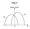
- the strengths of the low frequency signals outputted from the mixers MIX5 and MIX6 do not coincide with each other even if the input signals are equal in strength and phase.
- This is represented as shown in a characteristic diagram of Fig. 7 by way of example. Namely, when a signal strength S3 of the one channel CH1 is greater than a signal strength S4 of the other channel CH2 as illustrated in the characteristic diagram of Fig. 7, a signal corresponding to the sum of the two signals and a signal corresponding to the difference between the two signals are represented as a characteristic diagram shown in Fig. 8. Further, the ratio between the sum signal and the differential signal is represented as a characteristic R2 shown in Fig. 9.
- the monopulse radar Since the monopulse radar calculates an angle with a ratio R1 at the time that the characteristics of both channels are equal, as the base, it consequently outputs an angle ⁇ 1 other than 0° as the azimuth angle of the pseudo object detected by the signal for calibration.
- control signal generating means CNT1 In order to allow the angle ⁇ 1 to reach 0°, control signal generating means CNT1 generates a control signal so that the gain of the variable gain amplifier VGA1 is lowered.
- the strengths of the low frequency signals outputted from both channels become equal to each other and thereby result in the same form as Fig. 4.
- the angle correction of the monopulse radar system is automatically performed on a circuitry basis without human hands, the cost necessary for calibration work.
- Fig. 10 is a block diagram showing a configuration of another embodiment of a monopulse radar system according to the present invention.
- the present embodiment is an embodiment used in a vehicle radar using signals lying in a 77GHz band.
- Receive characteristics of receiving antennas ANT2 and ANT3 respectively have the receive patterns S1 and S2 symmetric about the center line as shown in Fig. 4.
- a common signal generator OSC1 is used for a signal generator for generating a transmit signal and signal generators for generating local signals inputted to mixers MIX1 and MIX2.
- a signal for calibration supplied to both channels CH1 and CH2 on the receiving side via a signal transmission line L1 for calibration passes through each of low noise amplifiers LNA1 and LNA2, after which they are converted into low frequency signals by mixers MIX1 and MIX2 .
- the low frequency signals are signal-analyzed by signal processing means P1, so that a pseudo target based on the signal for calibration is detected. Correction data is determined so that an azimuth angle to the pseudo target at this time reaches 0°, which in turn is stored in memory means MEM1.
- a switch SW1 When the monopulse radar system is normally operated as a vehicle-to-vehicle distance warning system, a switch SW1 is in a cutoff state, and the azimuth of a forward traveling vehicle, which is detected at this time, is corrected based on the correction data stored in the memory means MEM1.
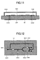
- Fig. 11 is a side cross-sectional view of one embodiment of an in-vehicle radar module which constitutes a monopulse radar system according to the present invention.
- the in-vehicle radar module includes an RF circuit RFC and a plane antenna ANT provided on the observe and reverse sides of a base plate B1. Both of the RF circuit RFC and the plane antenna ANT are connected to each other by coaxial transmission lines COX1 and COX2.
- the RF circuit RFC is covered with a cover COV1 to keep hermeticity.
- the RF circuit RFC takes such a configuration as shown in a plan view of Fig. 12.
- An MMIC (Monolithic Microwave Integrated Circuit) comprising a signal oscillator OSC1, mixers MIX1 and MIX2, low noise amplifiers LAN1 and LNA2, a switch SW1, etc. is packaged or mounted on a high-frequency substrate SUB1.
- a low frequency signal for switching the switch with a low frequency is supplied from a low frequency signal generator provided outside the module.
- the present module is suitable for automatically carrying out these by a signal processing device such as a microcomputer.
- Signal calibration may be carried out with specific timing when, for example, the power for the radar module is turned on.
- the corrections can be automatically performed even after shipment of a product.
- a vehicle radar corresponding even to environmental variations, time variations in parts characteristic, etc. can be fabricated.
- Fig. 13 is a plan view of one embodiment of part formed with the antennas referred to above.
- the present embodiment is an embodiment wherein a signal transmission line L1 for calibration is provided on the same substrate B1 as plane patch antennas for forming one transmitting antenna ANT1 and two receiving antenna ANT2 and ANT3 without being provided on the RF circuit side.
- calibration having taken into consideration even the influence of signal transmission lines COX1 and COX2 for connecting the surface of each antenna and the RF circuit can be performed and higher-accuracy calibration can be carried out.
- Fig. 14 is a plan view showing another embodiment of the part formed with the antennas.
- the present embodiment is a monopulse radar having four receiving antennas.
- transmitting/receiving antennas are made up of plane patch antennas.
- a transmitting antenna ANT1, four receiving antennas ANT4, ANT5, ANT6 and ANT7 arranged in parallel, and a signal transmission line L1 for calibration are respectively supplied with a calibration signal intended for the four receiving antennas ANT4, ANTS, ANT6 and ANT7 via a switch SW1 in equiphase form and at equal power.
- Fig. 15 is a circuit diagram showing one embodiment of the switch SW1.
- the switch SW1 is an MMIC formed according to a process similar to other MMIC.
- a switching diode D is electrically series-connected between an input IN and an output OUT via DC cut capacitances CAP1 and CAP2. Both ends of the switching diode D are supplied with a bias through transmission lines L4 and L5 and a DC cut capacitance CAP3.
- a control signal terminal CNT2 is provided between the transmission line L4 and the DC cut capacitance CAP3.
- Each of the DC cut capacitances CAP1, CAP2 and CAP3 has a large capacitance value assumed to be short-circuited for 77GHz.
- the bias supply transmission lines L4 and L5 are transmission lines whose leading ends are short-circuited, and respectively have lengths each equal to one-fourth a signal wave length of 77GHz.
- a bias circuit serves as high impedance in 77GHz and has no effect on the signal of 77GHz.
- a signal for bringing the switch into conduction/cut ⁇ off is supplied from the contro1 signal terminal CNT2.
- a transistor TR such as an FET may be used as shown in Fig. 16.
- a control signal terminal CNT2 serves as the gate of the FET.
- the angle correction of the monopulse radar can be easily carried out and its correction can also be automatically performed.
- the present monopulse radar can therefore cope even with variations in characteristic after product shipment due to environmental variations and time variations in parts characteristic. Further, the accuracy of an angle detected by a monopulse radar system can be maintained.
- ANT1 transmitting antenna
- ANT2 - ANT7 receiving antennas
- MIX1 - MIX6 mixers
- OSC1, OSC2 signal oscillators LNA1, LNA2: low noise amplifiers
- SW1 switch L1: signal transmission line for calibration
- L2 bias supply transmission line
- P1 signal processing means
- CNT1 control signal generating means
- CNT2 control signal terminal
- PS1 variable phase shifter
- VGA1 variable gain amplifier
- S1, S2 receive signal patterns of monopulse antennas
- S3, S4 receive signal patterns where error is developed between channels
- R1 ratio between sum signal and difference signal
- MEM1 memory means
- RFC RF circuit
- R2 ratio between sum signal and difference signal where error is developed between channels
- ANT plane antenna
- B1 base plate
- COX1, COX2 coaxial transmission lines
- COV1 cover
- SUB1 high-frequency circuit substrate
- D diode
- CAP DC cut capacitance
- TR FET
Landscapes
- Engineering & Computer Science (AREA)
- Radar, Positioning & Navigation (AREA)
- Remote Sensing (AREA)
- Computer Networks & Wireless Communication (AREA)
- Physics & Mathematics (AREA)
- General Physics & Mathematics (AREA)
- Radar Systems Or Details Thereof (AREA)
Abstract
Description
Claims (8)
- A monopulse radar system for radiating a transmit signal from a transmitting antenna (ANT1) and receiving a singal obtained by allowing the transmit signal to be reflected by a target with two or more receiving antennas to thereby detect the target, comprising :a calibration signal transmission line (L1) for supplying the transmit signal to each of signa1 transmission lines connected to the two or more receiving antennas as a signal for calibration; anda signal processing means (P1) for adjusting an azimuth angle of a pseudo target, detected by the signal for calibration, so as to reach a predetermined angle of the monopulse radar.
- The monopulse radar system according to claim 1, further including a switch (SW1) for bringing the calibration signal transmission line (L1) into a conducting state or a cutoff state.
- The monopulse radar system according to claim 2, further including switch driving means for producing the conducting state of said switch on a regular basis or with predetermined timing.
- The monopulse radar system according to claims 1 to 3, further including modulation means for modulating the signal for calibration with a low frequency signal.
- The monopulse radar system according to one of the claims 1 to 4, wherein said signal processing means (P1) is provided in correspondence with a channel for effecting signal processing on at least one receiving antenna, which includes correction means for correcting at least either the phase or amplitude of the calibration signal, and a control signal generating unit for driving the correction means.
- The monopulse radar system according to one of the claims 2 to 5, wherein said signal processing means (P1) includes means for bringing the switch (SW1) into a conducting state, calculating an azimuth angle of a pseudo target, which is detected by the signal for calibration, and determining correction data so that the calculated azimuth angle reaches a predetermined angle, memory means (MEM1) for storing the correction data therein, and correction means for effecting an angular correction, based on the correction data stored in the memory means (MEM1) upon calculation of the azimuth angle of the target.
- The monopulse radar system according to one of the claims 1 to 3, wherein the signal for calibration is supplied to output parts of the two or more receiving antennas at equal power and in equiphase fashion.
- A monopulse radar system for radiating a transmit signal from a transmitting antenna (ANT1), and receiving for receiving a signal obtained by allowing the transmit signal to be reflected by a target with two or more receiving antennas to thereby detect a target, comprising:a signal transmission line for connecting a transmission line connected to the transmitting antenna (ANT1) andtransmission lines connected to the two or more receiving antennas; anda switch (SW1) for bringing the signal transmission line into conduction or cutoff.
Applications Claiming Priority (2)
| Application Number | Priority Date | Filing Date | Title |
|---|---|---|---|
| JP2002050864 | 2002-02-27 | ||
| JP2002050864A JP2003248054A (en) | 2002-02-27 | 2002-02-27 | Monopulse radar device |
Publications (2)
| Publication Number | Publication Date |
|---|---|
| EP1341001A2 true EP1341001A2 (en) | 2003-09-03 |
| EP1341001A3 EP1341001A3 (en) | 2004-01-07 |
Family
ID=27678500
Family Applications (1)
| Application Number | Title | Priority Date | Filing Date |
|---|---|---|---|
| EP02019077A Withdrawn EP1341001A3 (en) | 2002-02-27 | 2002-08-28 | Monopulse radar system |
Country Status (3)
| Country | Link |
|---|---|
| US (2) | US6741205B2 (en) |
| EP (1) | EP1341001A3 (en) |
| JP (1) | JP2003248054A (en) |
Cited By (2)
| Publication number | Priority date | Publication date | Assignee | Title |
|---|---|---|---|---|
| RU2389038C2 (en) * | 2008-06-06 | 2010-05-10 | Открытое акционерное общество "Центральное конструкторское бюро аппаратостроения" | Monopulse radar with automatic calibration |
| CN107479041A (en) * | 2017-10-03 | 2017-12-15 | 中国人民解放军63686部队 | One kind builds station radar electric axis Detection of Stability method jointly |
Families Citing this family (54)
| Publication number | Priority date | Publication date | Assignee | Title |
|---|---|---|---|---|
| KR100548244B1 (en) * | 2003-03-14 | 2006-02-02 | 엘지전자 주식회사 | Low cost active smart antenna system and its manufacturing method |
| US7162200B2 (en) * | 2003-04-15 | 2007-01-09 | Chung Shan Institute Of Science And Technology | Antenna calibration system and method |
| DE112004002165T5 (en) * | 2003-11-18 | 2006-09-07 | Murata Mfg. Co., Ltd., Nagaokakyo | radar system |
| JP2005156337A (en) * | 2003-11-26 | 2005-06-16 | Hitachi Ltd | Automotive radar equipment |
| US7612706B2 (en) * | 2004-07-16 | 2009-11-03 | Fujitsu Ten Limited | Monopulse radar apparatus and antenna switch |
| DE102004040015B4 (en) * | 2004-08-16 | 2006-12-07 | S.M.S., Smart Microwave Sensors Gmbh | Method and device for detecting an electromagnetic signal emitted by a transmitting antenna |
| RU2298808C2 (en) * | 2005-06-28 | 2007-05-10 | Открытое акционерное общество "Корпорация "Фазотрон-Научно-исследовательский институт радиостроения" | Receiving arrangement for a monopulse radar |
| US7170440B1 (en) * | 2005-12-10 | 2007-01-30 | Landray Technology, Inc. | Linear FM radar |
| US7372398B2 (en) * | 2006-01-17 | 2008-05-13 | Lockheed Martin Corporation | Electronic target position control at millimeter wave for hardware-in-the-loop applications |
| US7623062B2 (en) * | 2006-08-01 | 2009-11-24 | Autoliv Asp, Inc. | System and method for target detection with a radar antenna |
| JP4846481B2 (en) * | 2006-08-02 | 2011-12-28 | 株式会社豊田中央研究所 | Radar equipment |
| JP4708298B2 (en) * | 2006-10-03 | 2011-06-22 | 三菱電機株式会社 | Transceiver circuit |
| KR100766414B1 (en) | 2006-10-26 | 2007-10-15 | 국방과학연구소 | Radar device capable of azimuth compensation and method thereof |
| JP2009008451A (en) * | 2007-06-26 | 2009-01-15 | Toyota Motor Corp | Broadband radar equipment |
| US9939526B2 (en) | 2007-09-06 | 2018-04-10 | Rockwell Collins, Inc. | Display system and method using weather radar sensing |
| US9354633B1 (en) | 2008-10-31 | 2016-05-31 | Rockwell Collins, Inc. | System and method for ground navigation |
| US9024805B1 (en) | 2012-09-26 | 2015-05-05 | Rockwell Collins, Inc. | Radar antenna elevation error estimation method and apparatus |
| US9733349B1 (en) | 2007-09-06 | 2017-08-15 | Rockwell Collins, Inc. | System for and method of radar data processing for low visibility landing applications |
| JP4722144B2 (en) * | 2008-01-10 | 2011-07-13 | 三菱電機株式会社 | Radar equipment |
| US7944391B2 (en) * | 2008-01-31 | 2011-05-17 | United Technologies Corporation | Correction for near field radar imaging |
| US8558731B1 (en) | 2008-07-02 | 2013-10-15 | Rockwell Collins, Inc. | System for and method of sequential lobing using less than full aperture antenna techniques |
| US7965225B1 (en) * | 2008-07-02 | 2011-06-21 | Rockwell Collins, Inc. | Radar antenna stabilization enhancement using vertical beam switching |
| US8077078B1 (en) | 2008-07-25 | 2011-12-13 | Rockwell Collins, Inc. | System and method for aircraft altitude measurement using radar and known runway position |
| US8026841B2 (en) * | 2008-09-18 | 2011-09-27 | Bae Systems Controls Inc. | Range and azimuth resolution enhancement for real-beam radar |
| JP4766405B2 (en) * | 2008-11-14 | 2011-09-07 | トヨタ自動車株式会社 | Radar equipment |
| EP2476163B1 (en) * | 2009-09-09 | 2018-07-25 | BAE Systems PLC | Antenna failure compensation |
| GB2473663B (en) * | 2009-09-21 | 2016-11-23 | Aveillant Ltd | Radar Receiver |
| JP2011130174A (en) * | 2009-12-17 | 2011-06-30 | Fujitsu Ltd | Communication device |
| DE102010012624A1 (en) * | 2010-03-24 | 2011-09-29 | Valeo Schalter Und Sensoren Gmbh | Driver assistance device for a vehicle and method for operating a radar device |
| CN101915909B (en) * | 2010-08-11 | 2013-05-08 | 四川九洲电器集团有限责任公司 | Implementing method for calibrating amplitude and phase of system receiving channel |
| RU2459219C1 (en) * | 2011-01-11 | 2012-08-20 | Открытое Акционерное Общество "Уральское проектно-конструкторское бюро "Деталь" | System for built-in control and calibration of monopulse radar station |
| DE102011012843A1 (en) | 2011-03-03 | 2012-09-06 | Valeo Schalter Und Sensoren Gmbh | Driver assistance device for a vehicle and method for operating a radar device |
| DE102011076840B4 (en) * | 2011-05-31 | 2013-08-01 | Johann Wolfgang Goethe-Universität Frankfurt am Main | A monolithically integrated antenna and receiver circuit and THz heterodyne receiver and imaging system comprising the same and use thereof for detecting electromagnetic radiation in the THz frequency range |
| US9019145B1 (en) | 2011-07-14 | 2015-04-28 | Rockwell Collins, Inc. | Ground clutter rejection for weather radar |
| US8692707B2 (en) | 2011-10-06 | 2014-04-08 | Toyota Motor Engineering & Manufacturing North America, Inc. | Calibration method for automotive radar using phased array |
| JP2013096908A (en) * | 2011-11-02 | 2013-05-20 | Honda Elesys Co Ltd | Radar apparatus for on-vehicle use, method for on-vehicle radar operation, and program for on-vehicle radar operation |
| JP5811931B2 (en) | 2012-04-04 | 2015-11-11 | トヨタ自動車株式会社 | Phase monopulse radar device |
| JP2014002053A (en) | 2012-06-19 | 2014-01-09 | Honda Elesys Co Ltd | On-vehicle rader system, on-vehicle radar method and on-vehicle radar program |
| US9170320B1 (en) * | 2012-12-03 | 2015-10-27 | Lockheed Martin Corporation | Transmitter pushing compensation for radar stability enhancement |
| US9262932B1 (en) | 2013-04-05 | 2016-02-16 | Rockwell Collins, Inc. | Extended runway centerline systems and methods |
| US9229100B2 (en) | 2013-09-20 | 2016-01-05 | Toyota Motor Engineering & Manufacturing North America, Inc. | Phased array radar with monopulse algorithm measurement |
| US10928510B1 (en) | 2014-09-10 | 2021-02-23 | Rockwell Collins, Inc. | System for and method of image processing for low visibility landing applications |
| US10705201B1 (en) | 2015-08-31 | 2020-07-07 | Rockwell Collins, Inc. | Radar beam sharpening system and method |
| CN105242265A (en) * | 2015-10-09 | 2016-01-13 | 四川九洲电器集团有限责任公司 | Self-adaptive control method and apparatus for inquiry frequency of secondary surveillance radar |
| KR101628183B1 (en) * | 2015-11-11 | 2016-06-08 | 국방과학연구소 | Rader comprising array antenna and method for calibrating phase of the same |
| US10228460B1 (en) | 2016-05-26 | 2019-03-12 | Rockwell Collins, Inc. | Weather radar enabled low visibility operation system and method |
| US10353068B1 (en) | 2016-07-28 | 2019-07-16 | Rockwell Collins, Inc. | Weather radar enabled offshore operation system and method |
| JP6910830B2 (en) * | 2017-04-04 | 2021-07-28 | 株式会社デンソーテン | Planar antenna device |
| KR102414149B1 (en) * | 2017-04-21 | 2022-06-30 | 호서대학교 산학협력단 | Frequency modulated continuous wave rader system having improved beam resolution |
| KR102222193B1 (en) * | 2019-09-06 | 2021-03-03 | 엘아이지넥스원 주식회사 | Direction detection control device and method of digital receiver system |
| CN110824449A (en) * | 2019-12-16 | 2020-02-21 | 西安电子工程研究所 | Automatic calibration test method for multi-frequency-point radar seeker |
| CN113514804B (en) * | 2021-06-29 | 2023-06-30 | 安徽隼波科技有限公司 | FMCW-based security radar angle measurement correction method |
| CN116125442A (en) * | 2022-12-07 | 2023-05-16 | 森思泰克河北科技有限公司 | Calibration system and radar for performing delay calibration on TDC timing channel |
| CN119414375B (en) * | 2025-01-03 | 2025-04-01 | 中安锐达(北京)电子科技有限公司 | Inter-travel detection method and system for vehicle-mounted radar |
Family Cites Families (19)
| Publication number | Priority date | Publication date | Assignee | Title |
|---|---|---|---|---|
| US3832711A (en) * | 1964-04-13 | 1974-08-27 | Raytheon Co | Guidance system |
| US4347513A (en) * | 1979-06-08 | 1982-08-31 | The United States Of America As Represented By The Secretary Of The Air Force | Netted search radar system |
| US4319242A (en) * | 1980-03-04 | 1982-03-09 | The United States Of America As Represented By The Secretary Of The Navy | Integrated weapon control radar system |
| JPS5712377A (en) * | 1980-06-26 | 1982-01-22 | Mitsubishi Electric Corp | Monopulse radar testing device |
| NL8204616A (en) * | 1982-11-29 | 1984-06-18 | Hollandse Signaalapparaten Bv | IMPULSE RADAR DEVICE. |
| JPS61108984A (en) * | 1984-11-01 | 1986-05-27 | Toshiba Corp | Radar equipment for measuring mono-pulse angle |
| JPH0299379A (en) | 1988-10-07 | 1990-04-11 | Nec Corp | Printer |
| JPH02180405A (en) | 1988-12-30 | 1990-07-13 | Nippon Mektron Ltd | Plane antenna board |
| JPH0331718A (en) | 1989-06-29 | 1991-02-12 | Komatsu Ltd | Digital phase detection circuit for resolver |
| JP2767986B2 (en) | 1990-07-18 | 1998-06-25 | 日本電気株式会社 | Tracking receiver |
| GB2289799B (en) * | 1991-09-17 | 1996-04-17 | Cossor Electronics Ltd | Improvements relating to radar antenna systems |
| JP2778326B2 (en) | 1992-02-05 | 1998-07-23 | 日本電気株式会社 | Secondary surveillance radar equipment |
| US5315304A (en) * | 1993-07-02 | 1994-05-24 | The United States Of America As Represented By The Secretary Of The Navy | Digital monopulse |
| US5493303A (en) | 1994-07-12 | 1996-02-20 | M/A-Com, Inc. | Monopulse transceiver |
| JPH08248122A (en) | 1995-03-15 | 1996-09-27 | Mitsubishi Electric Corp | Radar receiver |
| JPH0968568A (en) | 1995-08-31 | 1997-03-11 | Mitsubishi Electric Corp | Radar receiver |
| JPH09257921A (en) | 1996-03-27 | 1997-10-03 | Mitsubishi Electric Corp | Monopulse radar transceiver |
| JPH11271433A (en) | 1998-03-26 | 1999-10-08 | Toyota Central Res & Dev Lab Inc | Radar equipment |
| US6144333A (en) * | 1999-08-13 | 2000-11-07 | Raytheon Company | Method for estimating gain and phase imbalance using self-calibrating monopulse angle discriminants in a monopulse radar system |
-
2002
- 2002-02-27 JP JP2002050864A patent/JP2003248054A/en active Pending
- 2002-08-26 US US10/227,306 patent/US6741205B2/en not_active Expired - Fee Related
- 2002-08-28 EP EP02019077A patent/EP1341001A3/en not_active Withdrawn
-
2004
- 2004-04-06 US US10/817,874 patent/US7212152B2/en not_active Expired - Fee Related
Cited By (2)
| Publication number | Priority date | Publication date | Assignee | Title |
|---|---|---|---|---|
| RU2389038C2 (en) * | 2008-06-06 | 2010-05-10 | Открытое акционерное общество "Центральное конструкторское бюро аппаратостроения" | Monopulse radar with automatic calibration |
| CN107479041A (en) * | 2017-10-03 | 2017-12-15 | 中国人民解放军63686部队 | One kind builds station radar electric axis Detection of Stability method jointly |
Also Published As
| Publication number | Publication date |
|---|---|
| US7212152B2 (en) | 2007-05-01 |
| US6741205B2 (en) | 2004-05-25 |
| EP1341001A3 (en) | 2004-01-07 |
| US20030160718A1 (en) | 2003-08-28 |
| JP2003248054A (en) | 2003-09-05 |
| US20050190099A1 (en) | 2005-09-01 |
Similar Documents
| Publication | Publication Date | Title |
|---|---|---|
| EP1341001A2 (en) | Monopulse radar system | |
| US8405541B2 (en) | Multi-range radar system | |
| JP2989428B2 (en) | Time-sharing FM radar system | |
| CN101490578B (en) | FMCW-radarsensor | |
| JP2768439B2 (en) | FM-CW type multi-beam radar device | |
| US6034641A (en) | Antenna device | |
| US4742354A (en) | Radar transceiver employing circularly polarized waveforms | |
| JP2003248054A5 (en) | ||
| EP1832895B1 (en) | Method of detecting movements around automatic doors | |
| US6037894A (en) | Monostatic FMCW radar sensor | |
| US9482745B2 (en) | Driver assistance device for a vehicle and method for operating a radar device | |
| US9176228B2 (en) | Driver assistance device for a vehicle and method for operating a radar device | |
| US11879961B2 (en) | Radar array phase shifter verification | |
| CN1104088C (en) | Secondary surveillance radar | |
| JP2003248055A (en) | Monopulse radar system | |
| WO1999034234A1 (en) | A radar | |
| US6911934B2 (en) | Apparatus, method and articles of manufacture for sequential lobing high resolution radar | |
| JP3952610B2 (en) | High frequency circuit of FMCW radar device and FMCW radar device | |
| US7515093B2 (en) | Active antenna radar system | |
| JP3357585B2 (en) | In-vehicle radar device | |
| US20180284221A1 (en) | Radar apparatus | |
| Fredrick et al. | A novel single card FMCW radar transceiver with on board monopulse processing | |
| JP2748063B2 (en) | Time-division FM radar system | |
| JP4419288B2 (en) | Radar equipment | |
| JPH102953A (en) | Radar module |
Legal Events
| Date | Code | Title | Description |
|---|---|---|---|
| PUAI | Public reference made under article 153(3) epc to a published international application that has entered the european phase |
Free format text: ORIGINAL CODE: 0009012 |
|
| AK | Designated contracting states |
Kind code of ref document: A2 Designated state(s): AT BE BG CH CY CZ DE DK EE ES FI FR GB GR IE IT LI LU MC NL PT SE SK TR |
|
| AX | Request for extension of the european patent |
Extension state: AL LT LV MK RO SI |
|
| PUAL | Search report despatched |
Free format text: ORIGINAL CODE: 0009013 |
|
| AK | Designated contracting states |
Kind code of ref document: A3 Designated state(s): AT BE BG CH CY CZ DE DK EE ES FI FR GB GR IE IT LI LU MC NL PT SE SK TR |
|
| AX | Request for extension of the european patent |
Extension state: AL LT LV MK RO SI |
|
| RIC1 | Information provided on ipc code assigned before grant |
Ipc: 7G 01S 7/03 B Ipc: 7G 01S 7/40 B Ipc: 7G 01S 13/44 A |
|
| 17P | Request for examination filed |
Effective date: 20040628 |
|
| AKX | Designation fees paid |
Designated state(s): DE FR GB |
|
| 17Q | First examination report despatched |
Effective date: 20071129 |
|
| GRAP | Despatch of communication of intention to grant a patent |
Free format text: ORIGINAL CODE: EPIDOSNIGR1 |
|
| STAA | Information on the status of an ep patent application or granted ep patent |
Free format text: STATUS: THE APPLICATION IS DEEMED TO BE WITHDRAWN |
|
| 18D | Application deemed to be withdrawn |
Effective date: 20090623 |