EP1340973A1 - Light measuring device - Google Patents
Light measuring device Download PDFInfo
- Publication number
- EP1340973A1 EP1340973A1 EP02022460A EP02022460A EP1340973A1 EP 1340973 A1 EP1340973 A1 EP 1340973A1 EP 02022460 A EP02022460 A EP 02022460A EP 02022460 A EP02022460 A EP 02022460A EP 1340973 A1 EP1340973 A1 EP 1340973A1
- Authority
- EP
- European Patent Office
- Prior art keywords
- light
- sample
- optical path
- fluorescence
- phosphorescence
- Prior art date
- Legal status (The legal status is an assumption and is not a legal conclusion. Google has not performed a legal analysis and makes no representation as to the accuracy of the status listed.)
- Granted
Links
Images




Classifications
-
- G—PHYSICS
- G01—MEASURING; TESTING
- G01N—INVESTIGATING OR ANALYSING MATERIALS BY DETERMINING THEIR CHEMICAL OR PHYSICAL PROPERTIES
- G01N21/00—Investigating or analysing materials by the use of optical means, i.e. using sub-millimetre waves, infrared, visible or ultraviolet light
- G01N21/62—Systems in which the material investigated is excited whereby it emits light or causes a change in wavelength of the incident light
- G01N21/63—Systems in which the material investigated is excited whereby it emits light or causes a change in wavelength of the incident light optically excited
- G01N21/64—Fluorescence; Phosphorescence
-
- G—PHYSICS
- G01—MEASURING; TESTING
- G01N—INVESTIGATING OR ANALYSING MATERIALS BY DETERMINING THEIR CHEMICAL OR PHYSICAL PROPERTIES
- G01N21/00—Investigating or analysing materials by the use of optical means, i.e. using sub-millimetre waves, infrared, visible or ultraviolet light
- G01N21/62—Systems in which the material investigated is excited whereby it emits light or causes a change in wavelength of the incident light
- G01N21/63—Systems in which the material investigated is excited whereby it emits light or causes a change in wavelength of the incident light optically excited
- G01N21/64—Fluorescence; Phosphorescence
- G01N21/645—Specially adapted constructive features of fluorimeters
- G01N21/6452—Individual samples arranged in a regular 2D-array, e.g. multiwell plates
-
- G—PHYSICS
- G01—MEASURING; TESTING
- G01J—MEASUREMENT OF INTENSITY, VELOCITY, SPECTRAL CONTENT, POLARISATION, PHASE OR PULSE CHARACTERISTICS OF INFRARED, VISIBLE OR ULTRAVIOLET LIGHT; COLORIMETRY; RADIATION PYROMETRY
- G01J3/00—Spectrometry; Spectrophotometry; Monochromators; Measuring colours
- G01J3/02—Details
- G01J3/08—Beam switching arrangements
-
- G—PHYSICS
- G01—MEASURING; TESTING
- G01J—MEASUREMENT OF INTENSITY, VELOCITY, SPECTRAL CONTENT, POLARISATION, PHASE OR PULSE CHARACTERISTICS OF INFRARED, VISIBLE OR ULTRAVIOLET LIGHT; COLORIMETRY; RADIATION PYROMETRY
- G01J3/00—Spectrometry; Spectrophotometry; Monochromators; Measuring colours
- G01J3/28—Investigating the spectrum
- G01J3/44—Raman spectrometry; Scattering spectrometry ; Fluorescence spectrometry
- G01J3/4406—Fluorescence spectrometry
Definitions
- the present invention relates to a device for measuring fluorescence or phosphorescence emitted from a sample irradiated with excitation light, and more particularly to a fluorescence and phosphorescence measuring device capable of obtaining high detection sensitivity and SN ratio.
- a fluorescence and phosphorescence measuring device detects a target component in an article to be measured using a phenomenon that when excitation light such as an excitation lamp or laser light is irradiated to a sample to be measured, emitted light with a wavelength different from the wavelength of the irradiated excitation light.
- an actual measuring device at the time of measuring target emitted light from a sample, due to irradiation of exciting light to a sample container and an existing lens and filter, emittedlight, fluorescence, or phosphorescence other than light from the target is measured and the measured SN ratio may be reduced.
- the afterglow of exciting light enters into a light measuring device and the SN ratio may be reduced in the same way.
- fluorescence or phosphorescence hereinafter referred to as measurement interference light
- measurement interference light fluorescence or phosphorescence not from a sample is analyzed and measured as if the article to be measured is included in the sample though the article to be measured is not naturally included in the sample and an incorrect judgment may be made.
- scattered light or measurement interference light is varied in intensity, as a result, the minimum detection limit of an applied analytical measuring method or a measuring device is remarkably reduced.
- fluorescence is analyzed beforehand, and a raw material having smaller measurement interference light is selected and used as a material, and the use amount of material is reduced by making the material thinner, or the material surface is coated.
- the lamp and laser were improved so as to make an afterglow as little as possible after end of irradiation.
- the light measuring method in addition to the transmission surface fluorescence measuring method that the exciting light irradiation direction coincides with the light measuring direction, the side fluorescence measuring method that the direction does not coincides and light from the lamp and laser is not directly taken in the detection unit and the irradiation surface fluorescence measuring method are properly used.
- the difference between the exciting light wavelength and the fluorescence or phosphorescence wavelength is increased, and a wavelength selection filter is installed, and avoidance of detection of light with a wavelength adjacent to the exciting light wavelength is executed.
- time-resolved measuring method using a luminous body having a long fluorescence emission and phosphorescence emission continuous time and measuring fluorescence or phosphorescence during a time different from the exciting light irradiation time has been developed.
- exciting light is said not to be taken in the light measuring device, and therefore, it is a normal way to set the fluorescence measuring time to the time that the exciting light is off.
- it is a general method to turn on a flash lamp at 1000 Hz for 0.01 ms, measure between 0.4 ms and 0.8 ms after the lamp turns on, measure light in a 1-ms cycle, calculate the light quantity for 1 second, and display the data.
- a fluorescence measuring device or a phosphorescence measuring device as a light source, a tungsten lamp, a mercury lamp, an argon gas lamp, a xenon flash lamp, a nitrogen gas laser, or an argon gas laser is used.
- a light shielding plate or an optical path shut-off plate hereinafter referred to as a chopper
- a gap with a fixed size is formed, and the black plate is rotated, and exciting light generated from the light source passes only through the gap, thus exciting light at a fixed time interval is irradiated to a sample.
- the light source when the lamp is turned off, the light does not disappear instantaneously and the core of the light source reduces the light for a little while, thus even if the voltage is cut off, the light source generally emits light.
- the afterglow after the voltage is cut off lets the lens, filter, sample, or sample container of the light source or detection unit emit light sometimes, causing increasing of noise or background at the time of measurement.
- the afterglow has a wavelength different from the original one of the light emitted from the light source, so that when exciting light is to be separated from fluorescence or phosphorescence in wavelength, the afterglow may have the same or close wavelength to that of fluorescence or phosphorescence, causing increasing of noise at the time of measurement.
- it may be set so that the chopper ends breaking at the same time with or prior to turning off the power source of the light source.
- the exciting irradiation time to a sample and the measuring time of fluorescence or phosphorescence emitted from the sample are made different from each other, thus measurement of noise resulted from the exciting light is reduced and the sensitivity of measurement is increased.
- the chopper is put in front of the sample or the lens and filter of the light source and light other than the target is prevented from irradiation to the sample. Breaking by the chopper is synchronized with turning on or off the power source.
- the lens, filter, or mirror receiving irradiation of light emitted from the light source may scatter the light. Scattered light is preferably prevented from irradiation to the sample.
- the chopper is put on the optical path connecting the lamp and sample and light other than necessary light physically emitted from the light source is shielded.
- a physical shutter is installed or an electrical circuit shutter is set just behind the sample, thus exciting light is prevented from irradiation to the light quantity detector like photomultiplier tube.
- noise resulted from exciting light can be reduced and afterglow of the light source emitted after irradiation of exciting light and afterglow or scattered light from the lens, filter, mirror, or sample holder can be removed.
- the art disclosed in Japanese Laid-open Patent Publication No. Hei 10-267844 uses a first chopper so as to convert light to be entered to a sample to pulse light using the light source of exciting light as a continuous light source and uses a second chopper so as to detect only the target fluorescence or phosphorescence among light transmitted from the sample.
- a first chopper so as to convert light to be entered to a sample to pulse light using the light source of exciting light as a continuous light source
- a second chopper so as to detect only the target fluorescence or phosphorescence among light transmitted from the sample.
- the present invention is intended to provide a fluorescence and phosphorescence measuring device that choppers are inserted in a plurality of parts of the optical path from the light source to the detection unit, and fluorescence or phosphorescence emitted only from a sample can be measured effectively, and the number of choppers according to this is reduced to one, thus few troubles are caused due to a simple structure, and the price is low, and measurement is available in high sensitivity and at a high SN ratio.
- a fluorescence measuring device or phosphorescence measuring device of the present invention at the time of analysis and measurement of a sample, the optical path of exciting light emitted from the light source to the sample and the optical path of fluorescence or phosphorescence emitted from the sample to the light quantity detection unit are respectively shut off by using one light shielding plate.
- the source of exciting light does not need always to execute flashing (repetitively turning on and off) or generate a pulse and can be kept on continuously.
- increasing and decreasing of the light quantity irradiated to a sample can be controlled by a circular chopper by the size of the gap through which light passes and the rotational speed of the disk.
- a sample in a tubular or hollow container is irradiated by exciting light by a laser, and emitted phosphorescence or fluorescence is subjected to light measurement by a light measuring device or caught as an image of a CCD camera, and after data processing, the measured value is displayed or the sample is analyzed by using it.
- the lens or filter is known to emit fluorescence or phosphorescence due to irradiation of light. Exciting light preferably does not reach the lens or filter of the detection unit. When reflection (changing of the optical path), focusing, or scattering of light is necessary, a mirror is used. It is said that the aluminum metallic material of a reflecting mirror does not emit fluorescence and phosphorescence.
- Fig. 1 shows a system layout diagram of the embodiment of the present invention.
- a light source 1 such as a pulse generation light source like xenon flash lamp is focused by a lens system 2, passes through a selection filter 3 taking out only the wavelength component for excitation, then is focused by a focusing mirror 4 like dichroic mirror, and irradiated to a sample 6 distributed into a sample container 5 such as a microplate.
- Fluorescence or phosphorescence from the sample 6 is focused by a focusing mirror 7 on the opposite side, and short-wavelength light which is exciting light is removed, and the fluorescence or phosphorescence passes through a selection wave length filter 8 for taking out light having a necessary wavelength band and passes through a lens system 9, and the light quantity is converted through the detector like photomultiplier tube and its electric circuit.
- the exciting wavelength is set to about 340 nm and the wavelength of fluorescence of phosphorescence to be detected is set to about 615 nm.
- the aluminum metallic material of the reflecting mirror does not emit fluorescence and phosphorescence.
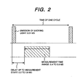
- Fig 2. shows an example of the timing chart of this time-resolved fluorescence measurement.
- the excitation light of pulse emission from the light source is only for a very short period such as about 0.01 ms.
- Fluorescence or phosphorescence from a sample excited by this light is set so as to open the gate of the light detector at a point of time 0.2 to 0.6 ms delayed after starting of emission of excitation light from the light source, thereafter measure for about 0.4 to 0.8 ms, close the gate of the signal detector, and move to the next exciting light emission timing.
- Fig. 3 shows a schematic view in the measurement timing of this system.
- the chopper is structured as shown in Fig. 4.
- a plurality of pairs of a slit 13 for passing light through the optical path between the light source and a sample to be measured and a light shielding part 14 for shielding light on the optical path between the sample to be measured and the detector are installed on the light shielding plate and each pair of a slit 13 and a light shielding part 14 are installed almost in the radial direction of the circular light shielding plate and positioned in different places in the radial direction.
- the position relationship between the slits and the light shielding parts in the radial direction can be set freely according to the arrangement way of the optical system. Further, “almost in the radial direction” is referred to as “almost on the same radius” and “almost” means “no need to be strictly in the same radial position”.
- Fig. 3 shows a schematic view at the measurement timing. By timing pulse generation of the light source, a timing chart as shown in Fig. 3 can be drawn.
- the chopper during irradiation to the sample 6 from the light source 1, shuts off the optical path to the light detector 10 from the sample 6 and does not lead light to the light detector 10. Further, the chopper may be structured so as to prevent light of the light source 1 from irradiation to the sample 6 during leading of light from the sample 6 to the detector 10.
- the repetitive measuring time can be shortened.
- the opening time of the slits for exciting light can be shortened sufficiently and even if the light source uses continuous light, pulse excitation can be realized.
- a pulse light source such as a flash lamp
- the slits trigger the pulse light source in the timing that exciting light passes through the optical path, the pulse light source can execute in the same way. In this case, passing through the slits must be monitored and a photocoupler not shown in the drawing may be used.
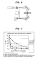
- Fig. 5 shows, when the optical path from the light source of exciting light to a sample is opened, the optical path of light emitted from the light source when the fluorescence or phosphorescence optical path from the sample to the detection unit is shut off. It is found that the light does not reach the lens and filter of the detection unit and unnecessary scattered light and fluorescence or phosphorescence are not generated in those parts.
- Fig. 6 shows, when the optical path from the light source of exciting light to the sample is shut off, the optical path of light generated from the sample when the fluorescence or phosphorescence optical path from the sample to the detection unit is opened. It is found that fluorescence or phosphorescence from the sample is caught by the light detector and exciting light or scattered light from the light source does not reach the detection unit.
- the background reduction effect of the present invention is shown in a schematic view in Fig. 7.
- Symbol A indicates that when a sample labeled with europium and its ligand via a complex suited to europium is used as protein, a sample excited by a xenon flash lamp emits phosphorescence. Phosphorescence decays with time, though the half-life of phosphorescence is comparatively long.
- Symbol B indicates decay of background noise when the present invention is not used and no chopper is used.
- the light quantity measured after flashing of the X enon flash lamp decays suddenly, though by stray light such as light emitted from the lens and filter other than the sample due to irradiation of afterglow or exciting light after turning the light source off, background noise is detected though it is low.
- Symbol C indicates decay of background noise when the present invention is used.
- Unnecessary light is not irradiated to the lens and filter of the light detector, and afterglow, scattered light, and stray light from the lens and filter on the exciting light side are not caught by the light detector, and fluorescence or phosphorescence resulted from them is not detected.
- the value of (light quantity obtained by A)/(light quantity obtained by C) is larger than the value of (light quantity obtained by A)/(light quantity obtained by B) and it is found that the SN ratio is greatly improved.
Landscapes
- Physics & Mathematics (AREA)
- Spectroscopy & Molecular Physics (AREA)
- General Physics & Mathematics (AREA)
- Health & Medical Sciences (AREA)
- Nuclear Medicine, Radiotherapy & Molecular Imaging (AREA)
- Life Sciences & Earth Sciences (AREA)
- Chemical & Material Sciences (AREA)
- Analytical Chemistry (AREA)
- Biochemistry (AREA)
- General Health & Medical Sciences (AREA)
- Immunology (AREA)
- Pathology (AREA)
- Investigating, Analyzing Materials By Fluorescence Or Luminescence (AREA)
Abstract
Description
Claims (7)
- A light measuring device comprising:a light source (1);an optical system (2, 3) for selecting, taking out, and focusing light with a wavelength necessary for measurement from light emitted from said light source (1);a detector (10) for irradiating said focused light to a sample (6) to be measured and detecting fluorescence or phosphorescence generated from said sample; andat least one optical path shielding mechanism (11, 12) respectively installed on an optical path between said light source (1) and said sample (6) to be measured, and an optical path between said sample to be measured and said detector (10), wherein said plurality of optical path shut-off mechanisms have a mechanism for shutting off said optical paths by a common light shielding plate (12).
- A fluorescence or phosphorescence measuring device according to Claim 1, wherein
said light source (1) is a light source continuously kept on, and said optical path shut-off mechanism (11, 12) between said sample (6) to be measured and said detector (10) operates so as to shut off said optical path in a time zone in which said light from said light source enters said sample to be measured, and
said optical path shut-off mechanism between said light source (1) and said sample (6) to be measured operates so as to shut off said optical path in a time zone in which said fluorescence or phosphorescence emitted from said sample to be measured enters said detector (10). - A fluorescence or phosphorescence measuring device according to Claim 1 or 2, wherein said light source (1) is a light source for generating a pulse.
- A fluorescence or phosphorescence measuring device according to Claim 1, 2 or 3, wherein said common light shielding plate (12) is circular and has installed a slit part (13) for passing light through said optical path between said light source (1) and said sample (6) to be measured, and a light shielding part (14) for shielding light on said optical path between said sample (6) to be measured and said detector (10), said slit part and light shielding part being paired on said light shielding plate.
- A fluorescence or phosphorescence measuring device according to Claim 4, wherein said pair of slit part (13) and light shielding part (14) are installed almost in a radial direction of said circular light shielding plate (12) and positioned in different places in said radial direction.
- A fluorescence or phosphorescence measuring device according to Claim 1 , wherein on said optical path between said common light shielding plates (12, 13, 14), no lens or filter emitting fluorescence or phosphorescence by irradiation of exciting light is used but a mirror (4, 7) is used for refraction of said optical path or focusing and scattering of light.
- A fluorescence or phosphorescence measuring device according to Claim 1, wherein at a time of measurement of fluorescence or phosphorescence, on both of an optical path from a lamp or a laser to a light quantity detector and said optical path from said light source (1) to said sample (6) and from said sample (6) to said detector (10), chopper plates (12, 13, 14) are incorporated and on an optical path held between said chopper plates, no lens and filter are used and irradiation of exciting light is not used and a mirror (4, 7) is used for refraction of said optical path or focusing and scattering of a light flux.
Applications Claiming Priority (2)
| Application Number | Priority Date | Filing Date | Title |
|---|---|---|---|
| JP2002006866 | 2002-01-16 | ||
| JP2002006866A JP2003207453A (en) | 2002-01-16 | 2002-01-16 | Fluorescence and phosphorescence measurement equipment |
Publications (2)
| Publication Number | Publication Date |
|---|---|
| EP1340973A1 true EP1340973A1 (en) | 2003-09-03 |
| EP1340973B1 EP1340973B1 (en) | 2007-05-02 |
Family
ID=19191283
Family Applications (1)
| Application Number | Title | Priority Date | Filing Date |
|---|---|---|---|
| EP02022460A Expired - Lifetime EP1340973B1 (en) | 2002-01-16 | 2002-10-04 | Light measuring device |
Country Status (6)
| Country | Link |
|---|---|
| US (1) | US6839134B2 (en) |
| EP (1) | EP1340973B1 (en) |
| JP (1) | JP2003207453A (en) |
| KR (1) | KR100495374B1 (en) |
| CN (1) | CN1210555C (en) |
| DE (1) | DE60219883T2 (en) |
Cited By (1)
| Publication number | Priority date | Publication date | Assignee | Title |
|---|---|---|---|---|
| DE102005045906A1 (en) * | 2005-09-26 | 2007-04-05 | Siemens Ag | Device for receiving a tissue containing a fluorescent dye |
Families Citing this family (33)
| Publication number | Priority date | Publication date | Assignee | Title |
|---|---|---|---|---|
| US7963695B2 (en) | 2002-07-23 | 2011-06-21 | Rapiscan Systems, Inc. | Rotatable boom cargo scanning system |
| US8275091B2 (en) | 2002-07-23 | 2012-09-25 | Rapiscan Systems, Inc. | Compact mobile cargo scanning system |
| US6928141B2 (en) | 2003-06-20 | 2005-08-09 | Rapiscan, Inc. | Relocatable X-ray imaging system and method for inspecting commercial vehicles and cargo containers |
| JP4662123B2 (en) * | 2004-09-24 | 2011-03-30 | 横河電機株式会社 | Laser confocal microscope system |
| US7471764B2 (en) | 2005-04-15 | 2008-12-30 | Rapiscan Security Products, Inc. | X-ray imaging system having improved weather resistance |
| US8119066B2 (en) * | 2006-02-08 | 2012-02-21 | Molecular Devices, Llc | Multimode reader |
| US7526064B2 (en) | 2006-05-05 | 2009-04-28 | Rapiscan Security Products, Inc. | Multiple pass cargo inspection system |
| CN101201322B (en) * | 2006-12-14 | 2011-05-18 | 上海通微分析技术有限公司 | Device with high sensitivity for detecting fluorescence |
| WO2009096252A1 (en) * | 2008-01-29 | 2009-08-06 | Konica Minolta Medical & Graphic, Inc. | Fluorescent detection unit and reaction detector |
| WO2009137875A1 (en) * | 2008-05-13 | 2009-11-19 | Macquarie University | Auto-synchronous fluorescence detection method and apparatus |
| GB0809110D0 (en) | 2008-05-20 | 2008-06-25 | Rapiscan Security Products Inc | Gantry scanner systems |
| US8963094B2 (en) | 2008-06-11 | 2015-02-24 | Rapiscan Systems, Inc. | Composite gamma-neutron detection system |
| GB0810638D0 (en) * | 2008-06-11 | 2008-07-16 | Rapiscan Security Products Inc | Photomultiplier and detection systems |
| JP5208801B2 (en) * | 2009-02-20 | 2013-06-12 | 株式会社東芝 | Photodetection device and paper sheet processing apparatus provided with the photodetection device |
| US9310323B2 (en) | 2009-05-16 | 2016-04-12 | Rapiscan Systems, Inc. | Systems and methods for high-Z threat alarm resolution |
| GB201018361D0 (en) * | 2010-11-01 | 2010-12-15 | Thompson Edward J | Fluorometry |
| EP2673660B1 (en) | 2011-02-08 | 2017-08-30 | Rapiscan Systems, Inc. | Covert surveillance using multi-modality sensing |
| WO2012111093A1 (en) * | 2011-02-15 | 2012-08-23 | 有限会社ワイ・システムズ | Method and device for measuring carrier lifetime |
| US9218933B2 (en) | 2011-06-09 | 2015-12-22 | Rapidscan Systems, Inc. | Low-dose radiographic imaging system |
| TWI476394B (en) * | 2012-04-02 | 2015-03-11 | Univ Chang Gung | And a method and method for determining whether a target biomolecule exists in a sample to be measured |
| WO2013163129A1 (en) * | 2012-04-23 | 2013-10-31 | Siemens Healthcare Diagnostics Inc. | Biological assay sample analyzer |
| CA2898654C (en) | 2013-01-31 | 2020-02-25 | Rapiscan Systems, Inc. | Portable security inspection system |
| US9448174B2 (en) * | 2013-03-28 | 2016-09-20 | Attomole Ltd | Fluorometry |
| US9557427B2 (en) | 2014-01-08 | 2017-01-31 | Rapiscan Systems, Inc. | Thin gap chamber neutron detectors |
| WO2015151812A1 (en) * | 2014-04-03 | 2015-10-08 | 株式会社日立ハイテクノロジーズ | Fluorometric analyzer |
| JP6797574B2 (en) * | 2016-06-16 | 2020-12-09 | オリンパス株式会社 | Scanning microscope |
| DE102019201440A1 (en) | 2019-02-05 | 2020-08-06 | Implen GmbH | Device for light spectroscopic analysis |
| EP4298433A4 (en) | 2021-02-23 | 2025-01-08 | Rapiscan Systems, Inc. | SYSTEMS AND METHODS FOR ELIMINATING CROSSTALK IN SCANNING SYSTEMS WITH MULTIPLE X-RAY SOURCES |
| KR102576472B1 (en) * | 2021-08-11 | 2023-09-11 | 주식회사 나노바이오라이프 | Multi channel optical diagnostic device |
| WO2024026152A1 (en) | 2022-07-26 | 2024-02-01 | Rapiscan Holdings, Inc. | Methods and systems for performing on-the-fly automatic calibration adjustments of x-ray inspection systems |
| WO2024050199A1 (en) | 2022-09-01 | 2024-03-07 | Rapiscan Holdings, Inc. | Systems and methods for classification of radiation energy spectra |
| WO2024186106A1 (en) * | 2023-03-06 | 2024-09-12 | 고려대학교 산학협력단 | System for analyzing photoluminescence signal on basis of time gate and operation method thereof |
| CN119394994B (en) * | 2025-01-06 | 2025-07-25 | 江西中医药大学 | Nondestructive testing method based on maltodextrin tablet |
Citations (4)
| Publication number | Priority date | Publication date | Assignee | Title |
|---|---|---|---|---|
| JPS60420A (en) * | 1983-06-17 | 1985-01-05 | Olympus Optical Co Ltd | Fluorescence microphotometric device |
| US4954714A (en) * | 1988-09-26 | 1990-09-04 | Hsc Research Development Corporation | Apparatus for time-resolved photography of fluorescence |
| JPH04106471A (en) * | 1990-08-28 | 1992-04-08 | Hitachi Ltd | Measuring device for biological substances |
| JP2001041889A (en) * | 1999-07-29 | 2001-02-16 | Mitsubishi Chemicals Corp | Modulation and fast time-resolved spectroscopy |
Family Cites Families (1)
| Publication number | Priority date | Publication date | Assignee | Title |
|---|---|---|---|---|
| JPH10267844A (en) | 1997-03-25 | 1998-10-09 | Jasco Corp | Time-resolved fluorescence detector and fluorescence analyzer and method using the same |
-
2002
- 2002-01-16 JP JP2002006866A patent/JP2003207453A/en active Pending
- 2002-09-27 US US10/255,623 patent/US6839134B2/en not_active Expired - Fee Related
- 2002-09-29 CN CNB021440034A patent/CN1210555C/en not_active Expired - Fee Related
- 2002-10-04 DE DE60219883T patent/DE60219883T2/en not_active Expired - Lifetime
- 2002-10-04 EP EP02022460A patent/EP1340973B1/en not_active Expired - Lifetime
-
2003
- 2003-01-15 KR KR10-2003-0002681A patent/KR100495374B1/en not_active Expired - Fee Related
Patent Citations (4)
| Publication number | Priority date | Publication date | Assignee | Title |
|---|---|---|---|---|
| JPS60420A (en) * | 1983-06-17 | 1985-01-05 | Olympus Optical Co Ltd | Fluorescence microphotometric device |
| US4954714A (en) * | 1988-09-26 | 1990-09-04 | Hsc Research Development Corporation | Apparatus for time-resolved photography of fluorescence |
| JPH04106471A (en) * | 1990-08-28 | 1992-04-08 | Hitachi Ltd | Measuring device for biological substances |
| JP2001041889A (en) * | 1999-07-29 | 2001-02-16 | Mitsubishi Chemicals Corp | Modulation and fast time-resolved spectroscopy |
Non-Patent Citations (5)
| Title |
|---|
| GYÖRGY VEREB ET AL: "Temporally and Spectrally Resolved Imaging Microscopy of Lanthanide Chelates", BIOPHYSICAL JOURNAL, vol. 74, no. 5, - 1998, pages 2210 - 2222, XP002246496, Retrieved from the Internet <URL:http://www.biophysj.org/cgi/reprint/74/5/2210> [retrieved on 20030704] * |
| PATENT ABSTRACTS OF JAPAN vol. 009, no. 113 (P - 356) 17 May 1985 (1985-05-17) * |
| PATENT ABSTRACTS OF JAPAN vol. 016, no. 348 (P - 1393) 28 July 1992 (1992-07-28) * |
| PATENT ABSTRACTS OF JAPAN vol. 2000, no. 19 5 June 2001 (2001-06-05) * |
| VERWOERD N P ET AL: "USE OF FERRO-ELECTRIC LIQUID CRYSTAL SHUTTERS FOR TIME-RESOLVED FLUORESCENCE MICROSCOPY", CYTOMETRY, ALAN LISS, NEW YORK, US, vol. 16, no. 2, 1 June 1994 (1994-06-01), pages 113 - 117, XP001106327, ISSN: 0196-4763 * |
Cited By (2)
| Publication number | Priority date | Publication date | Assignee | Title |
|---|---|---|---|---|
| DE102005045906A1 (en) * | 2005-09-26 | 2007-04-05 | Siemens Ag | Device for receiving a tissue containing a fluorescent dye |
| DE102005045906B4 (en) * | 2005-09-26 | 2007-11-29 | Siemens Ag | Device for receiving a tissue containing a fluorescent dye |
Also Published As
| Publication number | Publication date |
|---|---|
| EP1340973B1 (en) | 2007-05-02 |
| DE60219883T2 (en) | 2008-01-17 |
| CN1210555C (en) | 2005-07-13 |
| DE60219883D1 (en) | 2007-06-14 |
| US20030133107A1 (en) | 2003-07-17 |
| KR100495374B1 (en) | 2005-06-14 |
| KR20030062278A (en) | 2003-07-23 |
| JP2003207453A (en) | 2003-07-25 |
| CN1432804A (en) | 2003-07-30 |
| US6839134B2 (en) | 2005-01-04 |
Similar Documents
| Publication | Publication Date | Title |
|---|---|---|
| US6839134B2 (en) | Light measuring device avoiding influence of fluorescence or phosphorescence of lenses and filters in optical path | |
| CA2538701C (en) | Method for generating histogram | |
| EP0803724B1 (en) | Device using several optical measuring methods | |
| JP3790931B2 (en) | Fluorescence and phosphorescence detection apparatus and method | |
| US9939383B2 (en) | Analyzer alignment, sample detection, localization, and focusing method and system | |
| JPH05119035A (en) | Imaging flow sight meter | |
| JPH0643090A (en) | Particle analyzer | |
| Olesik et al. | Observation of atom and ion clouds produced from single droplets of sample in inductively coupled plasmas by optical emission and laser-induced fluorescence imaging | |
| EP0121404B1 (en) | A photometric light absorption measuring apparatus | |
| EP3531112B1 (en) | Raman spectroscopy detection device and sample safety detection method for use in raman spectroscopy detection | |
| JPH03503454A (en) | Optical reader for immunoassays | |
| TW202141021A (en) | Optical measuring device and optical measuring method | |
| JPS5811567B2 (en) | Back ground | |
| US20110189787A1 (en) | Spectrometer and method of operating a spectrometer | |
| JP2002005835A (en) | Raman spectrometer and biological sample analysis method using the same | |
| JP2005241624A (en) | Luminescence detection device | |
| EP0081947A1 (en) | Method and apparatus for normalizing radiometric measurements | |
| JP2005331319A (en) | Spectrofluorometer and sample cell | |
| JPH04343003A (en) | Detecting apparatus of fluorescence of semiconductor/ mask | |
| JP3676212B2 (en) | Fluorescence or phosphorescence measuring device | |
| US20080135741A1 (en) | Method for providing light signals for photometers and a photometer | |
| JPH11183385A (en) | Fluorescence analyzer | |
| JPH06308032A (en) | Fluorescence phosphorescence intensity meter | |
| Wu et al. | Spectral interferences and stray light in continuum source excited flame atomic-fluorescence spectrometry | |
| RU2038582C1 (en) | Dispersion-free atomic-fluorescent analyzer with wolfram spiral spray gun |
Legal Events
| Date | Code | Title | Description |
|---|---|---|---|
| PUAI | Public reference made under article 153(3) epc to a published international application that has entered the european phase |
Free format text: ORIGINAL CODE: 0009012 |
|
| AK | Designated contracting states |
Kind code of ref document: A1 Designated state(s): AT BE BG CH CY CZ DE DK EE ES FI FR GB GR IE IT LI LU MC NL PT SE SK TR |
|
| AX | Request for extension of the european patent |
Extension state: AL LT LV MK RO SI |
|
| 17P | Request for examination filed |
Effective date: 20040224 |
|
| AKX | Designation fees paid |
Designated state(s): CH DE FR GB LI NL |
|
| 17Q | First examination report despatched |
Effective date: 20050207 |
|
| GRAP | Despatch of communication of intention to grant a patent |
Free format text: ORIGINAL CODE: EPIDOSNIGR1 |
|
| GRAS | Grant fee paid |
Free format text: ORIGINAL CODE: EPIDOSNIGR3 |
|
| GRAA | (expected) grant |
Free format text: ORIGINAL CODE: 0009210 |
|
| AK | Designated contracting states |
Kind code of ref document: B1 Designated state(s): CH DE FR GB LI NL |
|
| REG | Reference to a national code |
Ref country code: GB Ref legal event code: FG4D |
|
| REG | Reference to a national code |
Ref country code: CH Ref legal event code: NV Representative=s name: TROESCH SCHEIDEGGER WERNER AG Ref country code: CH Ref legal event code: EP |
|
| REF | Corresponds to: |
Ref document number: 60219883 Country of ref document: DE Date of ref document: 20070614 Kind code of ref document: P |
|
| ET | Fr: translation filed | ||
| PLBE | No opposition filed within time limit |
Free format text: ORIGINAL CODE: 0009261 |
|
| STAA | Information on the status of an ep patent application or granted ep patent |
Free format text: STATUS: NO OPPOSITION FILED WITHIN TIME LIMIT |
|
| 26N | No opposition filed |
Effective date: 20080205 |
|
| PGFP | Annual fee paid to national office [announced via postgrant information from national office to epo] |
Ref country code: NL Payment date: 20080924 Year of fee payment: 7 |
|
| PGFP | Annual fee paid to national office [announced via postgrant information from national office to epo] |
Ref country code: GB Payment date: 20080922 Year of fee payment: 7 |
|
| PGFP | Annual fee paid to national office [announced via postgrant information from national office to epo] |
Ref country code: CH Payment date: 20081009 Year of fee payment: 7 |
|
| REG | Reference to a national code |
Ref country code: NL Ref legal event code: V1 Effective date: 20100501 |
|
| REG | Reference to a national code |
Ref country code: CH Ref legal event code: PL |
|
| PG25 | Lapsed in a contracting state [announced via postgrant information from national office to epo] |
Ref country code: NL Free format text: LAPSE BECAUSE OF NON-PAYMENT OF DUE FEES Effective date: 20100501 |
|
| PG25 | Lapsed in a contracting state [announced via postgrant information from national office to epo] |
Ref country code: CH Free format text: LAPSE BECAUSE OF NON-PAYMENT OF DUE FEES Effective date: 20091031 Ref country code: LI Free format text: LAPSE BECAUSE OF NON-PAYMENT OF DUE FEES Effective date: 20091031 |
|
| PG25 | Lapsed in a contracting state [announced via postgrant information from national office to epo] |
Ref country code: GB Free format text: LAPSE BECAUSE OF NON-PAYMENT OF DUE FEES Effective date: 20091004 |
|
| REG | Reference to a national code |
Ref country code: FR Ref legal event code: PLFP Year of fee payment: 14 |
|
| PGFP | Annual fee paid to national office [announced via postgrant information from national office to epo] |
Ref country code: FR Payment date: 20150908 Year of fee payment: 14 |
|
| PGFP | Annual fee paid to national office [announced via postgrant information from national office to epo] |
Ref country code: DE Payment date: 20150929 Year of fee payment: 14 |
|
| REG | Reference to a national code |
Ref country code: DE Ref legal event code: R119 Ref document number: 60219883 Country of ref document: DE |
|
| REG | Reference to a national code |
Ref country code: FR Ref legal event code: ST Effective date: 20170630 |
|
| PG25 | Lapsed in a contracting state [announced via postgrant information from national office to epo] |
Ref country code: FR Free format text: LAPSE BECAUSE OF NON-PAYMENT OF DUE FEES Effective date: 20161102 Ref country code: DE Free format text: LAPSE BECAUSE OF NON-PAYMENT OF DUE FEES Effective date: 20170503 |