EP1340901A2 - Noise attenuating segmented exhaust nozzle - Google Patents
Noise attenuating segmented exhaust nozzle Download PDFInfo
- Publication number
- EP1340901A2 EP1340901A2 EP03075601A EP03075601A EP1340901A2 EP 1340901 A2 EP1340901 A2 EP 1340901A2 EP 03075601 A EP03075601 A EP 03075601A EP 03075601 A EP03075601 A EP 03075601A EP 1340901 A2 EP1340901 A2 EP 1340901A2
- Authority
- EP
- European Patent Office
- Prior art keywords
- nozzle
- segmented
- wall
- exhaust
- region
- Prior art date
- Legal status (The legal status is an assumption and is not a legal conclusion. Google has not performed a legal analysis and makes no representation as to the accuracy of the status listed.)
- Granted
Links
Images


Classifications
-
- B—PERFORMING OPERATIONS; TRANSPORTING
- B64—AIRCRAFT; AVIATION; COSMONAUTICS
- B64D—EQUIPMENT FOR FITTING IN OR TO AIRCRAFT; FLIGHT SUITS; PARACHUTES; ARRANGEMENT OR MOUNTING OF POWER PLANTS OR PROPULSION TRANSMISSIONS IN AIRCRAFT
- B64D33/00—Arrangement in aircraft of power plant parts or auxiliaries not otherwise provided for
- B64D33/04—Arrangement in aircraft of power plant parts or auxiliaries not otherwise provided for of exhaust outlets or jet pipes
- B64D33/06—Silencing exhaust or propulsion jets
-
- F—MECHANICAL ENGINEERING; LIGHTING; HEATING; WEAPONS; BLASTING
- F02—COMBUSTION ENGINES; HOT-GAS OR COMBUSTION-PRODUCT ENGINE PLANTS
- F02K—JET-PROPULSION PLANTS
- F02K1/00—Plants characterised by the form or arrangement of the jet pipe or nozzle; Jet pipes or nozzles peculiar thereto
- F02K1/46—Nozzles having means for adding air to the jet or for augmenting the mixing region between the jet and the ambient air, e.g. for silencing
-
- F—MECHANICAL ENGINEERING; LIGHTING; HEATING; WEAPONS; BLASTING
- F02—COMBUSTION ENGINES; HOT-GAS OR COMBUSTION-PRODUCT ENGINE PLANTS
- F02K—JET-PROPULSION PLANTS
- F02K1/00—Plants characterised by the form or arrangement of the jet pipe or nozzle; Jet pipes or nozzles peculiar thereto
- F02K1/46—Nozzles having means for adding air to the jet or for augmenting the mixing region between the jet and the ambient air, e.g. for silencing
- F02K1/48—Corrugated nozzles
-
- F—MECHANICAL ENGINEERING; LIGHTING; HEATING; WEAPONS; BLASTING
- F05—INDEXING SCHEMES RELATING TO ENGINES OR PUMPS IN VARIOUS SUBCLASSES OF CLASSES F01-F04
- F05D—INDEXING SCHEME FOR ASPECTS RELATING TO NON-POSITIVE-DISPLACEMENT MACHINES OR ENGINES, GAS-TURBINES OR JET-PROPULSION PLANTS
- F05D2250/00—Geometry
- F05D2250/10—Two-dimensional
- F05D2250/11—Two-dimensional triangular
-
- F—MECHANICAL ENGINEERING; LIGHTING; HEATING; WEAPONS; BLASTING
- F05—INDEXING SCHEMES RELATING TO ENGINES OR PUMPS IN VARIOUS SUBCLASSES OF CLASSES F01-F04
- F05D—INDEXING SCHEME FOR ASPECTS RELATING TO NON-POSITIVE-DISPLACEMENT MACHINES OR ENGINES, GAS-TURBINES OR JET-PROPULSION PLANTS
- F05D2250/00—Geometry
- F05D2250/60—Structure; Surface texture
- F05D2250/61—Structure; Surface texture corrugated
- F05D2250/611—Structure; Surface texture corrugated undulated
-
- F—MECHANICAL ENGINEERING; LIGHTING; HEATING; WEAPONS; BLASTING
- F05—INDEXING SCHEMES RELATING TO ENGINES OR PUMPS IN VARIOUS SUBCLASSES OF CLASSES F01-F04
- F05D—INDEXING SCHEME FOR ASPECTS RELATING TO NON-POSITIVE-DISPLACEMENT MACHINES OR ENGINES, GAS-TURBINES OR JET-PROPULSION PLANTS
- F05D2250/00—Geometry
- F05D2250/70—Shape
- F05D2250/71—Shape curved
- F05D2250/713—Shape curved inflexed
Definitions
- This invention relates to exhaust nozzles used with turbofan engines, and more particularly to an exhaust nozzle used with a turbofan jet engine for reducing the noise of the exhaust gasses emitted from the engine without suppressing the flow of exhaust gasses through the exhaust nozzle.
- a jet noise reducing nozzle segment is typically triangular in planform and is contoured to increasingly immerse or extend into the exhaust flow with distance along its length.
- Multiple segments attached to the exit of a conventional exhaust nozzle are typically used to form a jet noise reducing segmented exhaust nozzle.
- the effective flow area of the exhaust nozzle is reduced when nozzle segments are employed due to the presence of portions of the nozzle segment projecting into the exhaust gas flow path. These portions, in effect, present additional blockage to the oncoming exhaust gas flow.
- the additional blockage results in reduced fan flutter margin which can negatively impact fan aero-elastic structural stability. It also can cause increased exhaust gas temperatures which can negatively impact turbine life.
- the present invention is directed to a segmented exhaust nozzle that effectively reduces the exhaust jet noise generated by a turbofan jet aircraft engine without adversely impacting engine operability or operability limit related performance.
- the exhaust nozzle is formed by a fan inner wall and a fan outer wall.
- the inner and outer walls cooperatively form an annular exhaust gas flow path therebetween.
- the walls further define a nozzle throat area and a nozzle exit area from which the exhaust gasses of a turbofan engine associated with the exhaust nozzle are emitted.
- the exhaust nozzle of the present invention provides a first region in which one of the inner or outer walls curves gradually towards the other, thereby presenting reduced cross-sectional area to exhaust gas flow in this region forming an aerodynamic throat.
- a second region through the segmented portion of the nozzle and downstream of the first region, is formed by the one wall curving away from the other wall to produce a region of increased cross-sectional area to exhaust gas flow.
- the second region forms an exhaust gas nozzle exit area which has an effective cross sectional area approximately equal to a conventional exhaust gas nozzle exit area.
- This is in contrast to previously developed, segmented exhaust nozzles in which the exhaust gas nozzle exit area is smaller in cross section than a conventional exhaust nozzle exit area. This difference effectively serves to eliminate the negative impact on engine operability and operability limit related performance introduced by previous segmented exhaust nozzle configurations while still providing a significant reduction in engine jet noise.
- the present invention thus reduces significantly the exhaust gas flow suppression that would typically be present with previous forms of segmented exhaust nozzles by presenting a geometric inflection through the flow control region of the nozzle.
- the inflective profile creates a conversion-divergent, cross sectional shape to the nozzle wall. The result is a net zero change in exhaust flow characteristic and a net zero change in segmented nozzle noise suppression effectiveness.
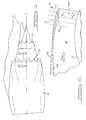
- FIG. 1 there is shown a segmented exhaust nozzle 10 in accordance with a preferred embodiment of the present invention.
- the exhaust nozzle 10 is particularly adapted for use with high bypass ratio turbofan jet engines.
- an external plug 11 is disposed within a housing structure forming a nacelle 18 along an imaginary axial center line ?C L ? of the nacelle.
- the segmented exhaust nozzle 10 includes a fan nozzle inner wall 12 and a fan nozzle outer wall 14 spaced apart from the inner wall 12. Cooperatively, the walls 12 and 14 form an annular exhaust gas flow path 16.
- the exhaust nozzle 10 is further typically contained within the nacelle 18, which also houses the turbofan jet engine (not shown).
- the outer wall 14 of the segmented exhaust nozzle 10 comprises a unique contour which effectively serves to reduce the exhaust jet noise generated by the turbofan jet engine without negatively impacting the operability or operability limit related performance of the engine.
- the outer wall 14 includes a portion curving gradually inwardly toward the inner wall 12 from a first point 20 to a second point 22 forming an aerodynamic choke point, or choke flow control region. From point 22, the outer wall 14 changes direction and curves gradually away from the inner wall 12 to a third point 24. Thereafter, the outer wall 14 again begins to curve towards the inner wall 12 to a fourth point 26. This is the segmented region of the nozzle.
- Point 22 also defines the location of the exhaust nozzle throat area (?A throat ?) while an integration of points 24 through 26 comprises the segmented exhaust nozzle exit area (?A exit ?).
- ?A E1 ? defines a point at which a conventional exhaust nozzle exit area would be located.
- ?A E1 through A E2 ? defines an exhaust nozzle exit area for a previously developed, typical segmented exhaust nozzle.
- points 20-24 define a first region in which the outer wall 14 forms an arcuate protrusion which projects into the exhaust gas flow path 16.
- the axial distance between points 24 and 26 defines a region of increased cross-sectional area to the exhaust gas flow.
- the edge of region two, points 24 through 26, provides an effective cross sectional area, represented by the imaginary line 26, which is approximately equal to A E1 , but still larger than A E2 .
- the entire wall structure between points 20 and 26 can be viewed as forming a geometric inflection in the exhaust gas flow path 16.
- the area between points 22 and 24 presents an increased cross-sectional area to the exhaust gas flow, thereby reducing blockage.
- the subsequent curvature back towards the inner wall 12 serves to realign the flow of exhaust gasses to maximize the nozzle noise reduction efficiency.
- the result is a segmented nozzle with distinct sonic and subsonic flow control regions yielding a net zero change in flow characteristic and a net zero change in segment noise suppression effectiveness of the segmented exhaust nozzle 10.
- outer wall 14 of the exhaust nozzle 10 has been illustrated as including the geometric influction surface, it will be appreciated that this surface could also be provided on the inner wall 12 of the exhaust nozzle 10.
- a graph 30 illustrates the reduction in exhaust gas flow noise with the segmented exhaust nozzle 10 of the present invention during a flight test.
- Figure 4 is a graph 32 illustrating the reduction in interior noise of an aircraft incorporating the segmented exhaust nozzle 10 of the present invention.
- Figure 5 illustrates a graph 32 of the flow characteristic of the segmented exhaust nozzle 10 of the present invention as compared to a conventional exhaust nozzle flow 34 and a flow characteristic of a previously developed, segmented nozzle design 36. From Figure 5 it will be appreciated that the flow characteristics of the exhaust nozzle 10 closely match those of a conventional exhaust nozzle.
- segmented exhaust nozzle 10 of the present invention provides a means to significantly attenuate the exhaust jet noise produced by turbofan engines, and thus help to meet increasingly stringent community noise requirements. Importantly, the exhaust nozzle 10 does not adversely impact the operation or operability limit related performance of existing large turbofan jet engines.
- the segmented exhaust nozzle 10 is further capable of being used as a segmented nozzle in exhaust nozzles having an internal primary plug, such that no inner wall is present.
- the outer wall 14 would curve with reference to the imaginary center line C L , since no inner wall would be present.
Landscapes
- Engineering & Computer Science (AREA)
- Chemical & Material Sciences (AREA)
- Combustion & Propulsion (AREA)
- Mechanical Engineering (AREA)
- General Engineering & Computer Science (AREA)
- Aviation & Aerospace Engineering (AREA)
- Exhaust Silencers (AREA)
- Structures Of Non-Positive Displacement Pumps (AREA)
Abstract
Description
Claims (14)
- A segmented flow nozzle for use with a jet engine to inhibit jet exhaust noise emitted from the jet engine, said flow nozzle comprising:a circumferential nozzle inner wall;a circumferential nozzle outer wall spaced apart from said inner wall to define an annular flow path therebetween;one of said inner and outer walls curving toward the other to define a protrusion, that which extends into said exhaust gas flow path to reduce a cross sectional area of said exhaust gas flow path, thereby forming a choke flow control region;said flow nozzle including a segmented region downstream of said choke flow control region;through the segmented region of the nozzle, said one wall gradually curving away from the other, and then back toward the other, to provide define an increased cross-sectional area for un-choked flow control; anda downstream edge of said segmented region defining a nozzle exit area having an effective cross sectional area approximately equal to a non-segmented nozzle exit area.
- The nozzle of claim 1, wherein a midpoint of said segmented region defines a cross sectional area which is larger than said non-segmented nozzle exit area.
- The nozzle of claim 1, wherein said nozzle forms an extension of an existing nozzle structure.
- A segmented exhaust nozzle for use with a jet engine to inhibit exhaust jet noise emitted from the jet engine, said exhaust nozzle comprising:wherein an edge of said downstream region defines a nozzle exit having an effective cross sectional area approximately equal to a non-segmented exhaust nozzle exit area.a circumferential nozzle inner wall;a circumferential nozzle outer wall spaced apart from said inner wall to define an annular exhaust gas flow path therebetween said circumferential nozzle outer wall, in cooperation with said circumferential nozzle inner wall, forming a plurality os spaced apart segmented regions of the exhaust nozzle;said outer wall curving toward the inner wall to define an arcuate protrusion that extends into said exhaust gas flow path to reduce a cross sectional area of said annular exhaust gas flow path and thereby provide a choke flow control region along the annular exhaust gas flow path;said segmented regions being disposed downstream of said choke flow control region;said outer wall gradually curving away from the inner wall, and then back toward the inner wall, to define regions downstream of said arcuate protrusion for providing increased cross-sectional area for un-choked flow control to said exhaust gas flowing through said annular exhaust gas flow path; and
- The exhaust nozzle of claim 4, wherein a midpoint of said region defines a larger cross sectional area than said edge of each said region.
- The exhaust nozzle of claim 5, wherein said midpoint defines a larger cross sectional area than said conventional exhaust nozzle exit area.
- A segmented exhaust nozzle for use with a jet engine exhaust nozzle structure, said exhaust nozzle comprising:wherein said cross sectional area integrated between said third point and said fourth point is effectively equal to a cross section area at said intermediate point.a nozzle inner wall;a nozzle outer wall spaced apart from said fan nozzle inner wall;said nozzle inner and outer walls forming said exhaust nozzle and having a nozzle throat area and a nozzle exit area downstream from said nozzle throat area;at least one of said nozzle inner and outer walls curving gradually toward the other from a first point to a second point positioned downstream of said first point, relative to flow through said jet engine, to thereby reduce a cross sectional area between said nozzle walls to form an aerodynamic throat area of said segmented exhaust nozzle;said exhaust nozzle including a plurality of segmented regions downstream of said throat area;through each said segmented region of the exhaust nozzle, said at least one of said walls then curving gradually away from the other from said second point to a third point downstream of said second point, relative to said flow through said jet engine, to thereby effectively increase the cross sectional area presented to the flow within said segmented exhaust nozzle, and wherein an intermediate point between said second and third points defines where a conventional nozzle exit point is located on a non-segmented exhaust nozzle;further through the segmented region of the nozzle downstream of said third point, said at least one of said walls then curving gradually toward the other from said third point to a fourth point downstream of said third point, relative to said flow, to thereby reduce a cross sectional distance between the walls within said segmented exhaust nozzle at said fourth point; and
- The exhaust nozzle of claim 7, wherein a region between said first and second points represents an arcuate protrusion to accelerate said flow.
- The exhaust nozzle of claim 7, wherein a region between said second and fourth points presents increased cross sectional area for subsonic flow control.
- A segmented exhaust nozzle for use with a jet engine fan exhaust nozzle structure, said exhaust nozzle comprising:wherein an intermediate point between said second and third points defines where a non-segmented nozzle exit point is located on a conventional exhaust nozzle; anda fan nozzle inner wall;a fan nozzle outer wall spaced apart from said fan nozzle inner wall to form an annular exhaust gas flow path;said exhaust nozzle having a nozzle throat area and a nozzle exit area downstream from said nozzle throat area;said outer wall curving gradually toward the inner wall from a first point to a second point positioned downstream of said first point, relative to exhaust gas flow through said nozzle, to thereby reduce a nozzle throat cross sectional area of said exhaust nozzle and accelerate said exhaust gas flow therethrough;said exhaust nozzle including a segmented region downstream of said point;through said segmented region of the nozzle, said outer wall then curving gradually away from the inner wall from said second point to a third point downstream of said second point, relative to said exhaust gas flow, to thereby effectively increase the cross sectional area presented to said exhaust gas flow within said exhaust nozzle
said outer wall then curving gradually toward the inner wall from said third point to a fourth point downstream of said third point, relative to said exhaust gas flow; and
wherein said cross sectional area integrated through said third point and said fourth point is substantially equal to a cross section area at said intermediate point. - The exhaust nozzle of claim 10, wherein a region between said first and third points defines an arcuate protrusion.
- A segmented nozzle for use with a jet engine to inhibit jet exhaust noise emitted from the jet engine, said exhaust nozzle comprising:a nozzle outer wall spaced apart from an imaginary axial center line of said nozzle;said outer wall curving toward said imaginary axial center line to define a protrusion that extends into said exhaust gas flow path to reduce a cross sectional area of said exhaust gas flow path, thereby forming a choke flow control region;said nozzle including a segmented region downstream of said choke flow control region;through the segmented region of nozzle, said outer wall gradually curving away from said imaginary axial center line, and then back toward said center line, to define said segmented region which provides an increased cross-sectional area for un-choked flow control; anda downstream edge of said second region defining a nozzle exit area having an effective cross sectional area approximately equal to a non-segmented exhaust nozzle exit area.
- A segmented flow nozzle for use with a jet engine to inhibit engine noise emitted from the engine, said flow nozzle comprising;a nozzle inner wall;a nozzle outer wall spaced apart from said inner wall to define a flow path therebetween;one of the inner and outer walls curving toward the other at first region of said flow path to reduce a cross sectional area of said flow path; and form a choke flow region;the segmented region being downstream of said choke flow control region;through the segmented region of the nozzle, one of said inner and outer walls curving away from the other, and then back toward the other, to define said segmented region such that said segmented region has said walls diverging from one another and then converging toward one another in a direction of said flow through said jet engine; anda downstream edge of said segmented region defining a nozzle exit area having a cross sectional area approximately equal to a non-segmented jet engine nozzle exit area.
- A method for inhibiting noise emitted from a jet engine, comprising:using a nozzle inner wall and a nozzle outer wall to form a segmented flow nozzle that provides a flow path therebetween for an exhaust flow through said jet engine;defining a first flow region within said flow nozzle having a first cross sectional area that acts as a constriction in said flow path; and thereby forms a choke flow control region;defining a segmented nozzle region downstream of said choke flow control region, relative to a direction of airflow through said flow path, which has a second cross sectional area and a third cross sectional area, wherein said second cross sectional area is larger than said first cross sectional area; andforming a downstream edge of said segmented nozzle region such that a nozzle exit area thereof has an effective cross sectional area approximately equal to that of a non-segmented nozzle exit area.
Applications Claiming Priority (2)
| Application Number | Priority Date | Filing Date | Title |
|---|---|---|---|
| US87582 | 2002-02-28 | ||
| US10/087,582 US6658839B2 (en) | 2002-02-28 | 2002-02-28 | Convergent/divergent segmented exhaust nozzle |
Publications (3)
| Publication Number | Publication Date |
|---|---|
| EP1340901A2 true EP1340901A2 (en) | 2003-09-03 |
| EP1340901A3 EP1340901A3 (en) | 2004-12-29 |
| EP1340901B1 EP1340901B1 (en) | 2016-09-21 |
Family
ID=27733440
Family Applications (1)
| Application Number | Title | Priority Date | Filing Date |
|---|---|---|---|
| EP03075601.9A Expired - Lifetime EP1340901B1 (en) | 2002-02-28 | 2003-02-28 | Noise attenuating segmented exhaust nozzle |
Country Status (2)
| Country | Link |
|---|---|
| US (2) | US6658839B2 (en) |
| EP (1) | EP1340901B1 (en) |
Cited By (11)
| Publication number | Priority date | Publication date | Assignee | Title |
|---|---|---|---|---|
| US7305817B2 (en) | 2004-02-09 | 2007-12-11 | General Electric Company | Sinuous chevron exhaust nozzle |
| FR2914020A1 (en) * | 2007-03-23 | 2008-09-26 | Airbus France Sas | METHOD FOR REDUCING THE SOUND EMISSIONS AT THE BACK OF A TURBOMOTEUR AND TURBOMOTEUR PERFECTED BY THE PROCESS |
| FR2920035A1 (en) * | 2007-08-17 | 2009-02-20 | Airbus France Sas | TURBOMOTEUR WITH REDUCED NOISE TRANSMISSION FOR AIRCRAFT |
| EP1619376A3 (en) * | 2004-07-23 | 2011-12-14 | General Electric Company | Split shroud exhaust nozzle |
| FR2986832A1 (en) * | 2012-02-10 | 2013-08-16 | Snecma | METHOD FOR DEFINING THE FORM OF A CONVERGENT-DIVERGENT TUBE OF A CORRESPONDING TURBOMACHINE AND CONVERGENT-DIVERGENT TUBE |
| WO2015007987A1 (en) * | 2013-07-18 | 2015-01-22 | Snecma | Nozzle of a turbomachine provided with chevrons with a non-axisymmetric inner face |
| EP3001019A1 (en) * | 2014-09-25 | 2016-03-30 | The Boeing Company | Methods and apparatus for passive thrust vectoring and plume deflection |
| US9546618B2 (en) | 2013-10-24 | 2017-01-17 | The Boeing Company | Methods and apparatus for passive thrust vectoring and plume deflection |
| GB2542287A (en) * | 2014-09-03 | 2017-03-15 | Boeing Co | Core cowl for a turbofan engine |
| GB2531138B (en) * | 2014-09-03 | 2017-03-22 | Boeing Co | Core cowl for a turbofan engine |
| US9732700B2 (en) | 2013-10-24 | 2017-08-15 | The Boeing Company | Methods and apparatus for passive thrust vectoring and plume deflection |
Families Citing this family (33)
| Publication number | Priority date | Publication date | Assignee | Title |
|---|---|---|---|---|
| US7065957B2 (en) * | 2000-05-05 | 2006-06-27 | The Boeing Company | Segmented mixing device for jet engines and aircraft |
| FR2829802B1 (en) * | 2001-09-19 | 2004-05-28 | Centre Nat Rech Scient | DEVICE FOR CONTROLLING MIXTURE OF PROPELLENT JETS FOR AN AIRCRAFT REACTOR |
| US7055329B2 (en) * | 2003-03-31 | 2006-06-06 | General Electric Company | Method and apparatus for noise attenuation for gas turbine engines using at least one synthetic jet actuator for injecting air |
| US20040244357A1 (en) * | 2003-06-05 | 2004-12-09 | Sloan Mark L. | Divergent chevron nozzle and method |
| US7246481B2 (en) * | 2004-03-26 | 2007-07-24 | General Electric Company | Methods and apparatus for operating gas turbine engines |
| US7377109B2 (en) * | 2004-04-09 | 2008-05-27 | The Boeing Company | Apparatus and method for reduction of jet noise from turbofan engines having separate bypass and core flows |
| US7377108B2 (en) * | 2004-04-09 | 2008-05-27 | The Boeing Company | Apparatus and method for reduction jet noise from single jets |
| GB0505246D0 (en) * | 2005-03-15 | 2005-04-20 | Rolls Royce Plc | Engine noise |
| FR2885955B1 (en) * | 2005-05-18 | 2007-06-22 | Airbus France Sas | METHOD FOR REDUCING THE SOUND EMISSIONS AT THE BACK OF A TURBOMOTEUR AND TURBOMOTEUR THUS PERFECTED. |
| US7543452B2 (en) * | 2005-08-10 | 2009-06-09 | United Technologies Corporation | Serrated nozzle trailing edge for exhaust noise suppression |
| US20070281600A1 (en) * | 2006-05-31 | 2007-12-06 | Prakash Thawani | Air distribution system having a noise reduction feature for use with an automotive vehicle |
| FR2902837B1 (en) * | 2006-06-26 | 2008-10-24 | Snecma Sa | TURBOMACHINE TUBE HOOD WITH TRIANGULAR DOUBLE-SUMMIT PATTERNS TO REDUCE JET NOISE |
| US7966824B2 (en) | 2006-08-09 | 2011-06-28 | The Boeing Company | Jet engine nozzle exit configurations and associated systems and methods |
| US8157207B2 (en) * | 2006-08-09 | 2012-04-17 | The Boeing Company | Jet engine nozzle exit configurations, including projections oriented relative to pylons, and associated systems and methods |
| US8015819B2 (en) * | 2006-09-29 | 2011-09-13 | The United States Of America As Represented By The Administrator Of The National Aeronautics And Space Administration | Wet active chevron nozzle for controllable jet noise reduction |
| US7870722B2 (en) * | 2006-12-06 | 2011-01-18 | The Boeing Company | Systems and methods for passively directing aircraft engine nozzle flows |
| JP4830836B2 (en) * | 2006-12-18 | 2011-12-07 | 株式会社Ihi | Jet jet exhaust nozzle and jet engine |
| US7966826B2 (en) * | 2007-02-14 | 2011-06-28 | The Boeing Company | Systems and methods for reducing noise from jet engine exhaust |
| US7883049B2 (en) * | 2007-04-27 | 2011-02-08 | The Boeing Company | Jet nozzle having noise attenuating shield and method therefor |
| US7963099B2 (en) * | 2007-05-21 | 2011-06-21 | General Electric Company | Fluted chevron exhaust nozzle |
| US7926285B2 (en) * | 2007-07-18 | 2011-04-19 | General Electric Company | Modular chevron exhaust nozzle |
| FR2929336B1 (en) * | 2008-03-31 | 2012-06-01 | Airbus France | JET DEVICE NOISE REDUCTION PLATES GENERATED BY AN AIRCRAFT REACTOR |
| FR2930972B1 (en) * | 2008-05-07 | 2012-11-30 | Airbus France | DOUBLE FLOW TURBOMACHINE FOR AIRCRAFT WITH REDUCED NOISE TRANSMISSION |
| US8776527B1 (en) | 2008-06-17 | 2014-07-15 | Rolls-Royce North American Technologies, Inc. | Techniques to reduce infrared detection of a gas turbine engine |
| US8459036B2 (en) | 2008-12-26 | 2013-06-11 | Rolls-Royce Corporation | Aircraft nozzle having actuators capable of changing a flow area of the aircraft nozzle |
| JP5572060B2 (en) | 2010-10-22 | 2014-08-13 | 株式会社やまびこ | Air blower |
| US20140182309A1 (en) * | 2012-12-28 | 2014-07-03 | United Technologies Corporation | Geared gas turbine engine exhaust nozzle with chevrons |
| EP2971656B1 (en) * | 2013-03-15 | 2020-03-04 | United Technologies Corporation | Aerodynamic track fairing for a gas turbine engine fan nacelle |
| US9145801B2 (en) * | 2013-07-01 | 2015-09-29 | The Boeing Company | Systems and methods for acoustic resonance mitigation |
| EP2837795B1 (en) | 2013-08-14 | 2019-05-01 | Ansaldo Energia IP UK Limited | Improved intake arrangement in gas turbine power plant |
| PL414889A1 (en) | 2015-11-23 | 2017-06-05 | General Electric Company | Jet engine outlet compression cowling |
| CN115539246B (en) * | 2022-08-26 | 2025-09-26 | 西北工业大学 | An S-bend nozzle with deformation suppression structure and aircraft engine |
| US11920539B1 (en) | 2022-10-12 | 2024-03-05 | General Electric Company | Gas turbine exhaust nozzle noise abatement |
Family Cites Families (10)
| Publication number | Priority date | Publication date | Assignee | Title |
|---|---|---|---|---|
| US3153319A (en) * | 1952-07-25 | 1964-10-20 | Young Alec David | Jet noise suppression means |
| US2944623A (en) * | 1955-09-02 | 1960-07-12 | Jr Albert G Bodine | Jet engine noise reducer |
| US5216878A (en) * | 1991-06-28 | 1993-06-08 | The Boeing Company | Mixed exhaust flow supersonic jet engine and method |
| GB2289921A (en) * | 1994-06-03 | 1995-12-06 | A E Harris Limited | Nozzle for turbofan aeroengines |
| US5771681A (en) * | 1996-09-17 | 1998-06-30 | The Boeing Company | Aircraft turbofan engine mixing apparatus |
| US6360528B1 (en) * | 1997-10-31 | 2002-03-26 | General Electric Company | Chevron exhaust nozzle for a gas turbine engine |
| US6314721B1 (en) * | 1998-09-04 | 2001-11-13 | United Technologies Corporation | Tabbed nozzle for jet noise suppression |
| US6487848B2 (en) * | 1998-11-06 | 2002-12-03 | United Technologies Corporation | Gas turbine engine jet noise suppressor |
| US6612106B2 (en) * | 2000-05-05 | 2003-09-02 | The Boeing Company | Segmented mixing device having chevrons for exhaust noise reduction in jet engines |
| US6532729B2 (en) * | 2001-05-31 | 2003-03-18 | General Electric Company | Shelf truncated chevron exhaust nozzle for reduction of exhaust noise and infrared (IR) signature |
-
2002
- 2002-02-28 US US10/087,582 patent/US6658839B2/en not_active Expired - Lifetime
-
2003
- 2003-02-28 EP EP03075601.9A patent/EP1340901B1/en not_active Expired - Lifetime
- 2003-10-13 US US10/685,173 patent/US6826901B2/en not_active Expired - Lifetime
Cited By (23)
| Publication number | Priority date | Publication date | Assignee | Title |
|---|---|---|---|---|
| US7305817B2 (en) | 2004-02-09 | 2007-12-11 | General Electric Company | Sinuous chevron exhaust nozzle |
| EP1619376A3 (en) * | 2004-07-23 | 2011-12-14 | General Electric Company | Split shroud exhaust nozzle |
| FR2914020A1 (en) * | 2007-03-23 | 2008-09-26 | Airbus France Sas | METHOD FOR REDUCING THE SOUND EMISSIONS AT THE BACK OF A TURBOMOTEUR AND TURBOMOTEUR PERFECTED BY THE PROCESS |
| WO2008129177A1 (en) * | 2007-03-23 | 2008-10-30 | Airbus France | Method for reducing noise output at the back of a turboshaft engine and turboshaft engine improved by this method |
| US8607452B2 (en) | 2007-03-23 | 2013-12-17 | Airbus Operations Sas | Method for reducing sound output at the back of a turbo engine and turbo engine improved by this method |
| FR2920035A1 (en) * | 2007-08-17 | 2009-02-20 | Airbus France Sas | TURBOMOTEUR WITH REDUCED NOISE TRANSMISSION FOR AIRCRAFT |
| WO2009053555A1 (en) * | 2007-08-17 | 2009-04-30 | Airbus France | Turboshaft engine with reduced noise emission for aircraft |
| JP2010537098A (en) * | 2007-08-17 | 2010-12-02 | エアバス オペレーションズ (エスアーエス) | Aircraft turboshaft engine with reduced injection noise |
| RU2451814C2 (en) * | 2007-08-17 | 2012-05-27 | Эрбюс Операсьон (Сас) | Aircraft turbojet low-noise engine |
| FR2986832A1 (en) * | 2012-02-10 | 2013-08-16 | Snecma | METHOD FOR DEFINING THE FORM OF A CONVERGENT-DIVERGENT TUBE OF A CORRESPONDING TURBOMACHINE AND CONVERGENT-DIVERGENT TUBE |
| WO2015007987A1 (en) * | 2013-07-18 | 2015-01-22 | Snecma | Nozzle of a turbomachine provided with chevrons with a non-axisymmetric inner face |
| FR3008739A1 (en) * | 2013-07-18 | 2015-01-23 | Snecma | TUYERE OF A TURBOMACHINE EQUIPPED WITH CHEVRONS WITH NON-AXI-SYMMETRIC INTERNAL SIDE. |
| GB2532892A (en) * | 2013-07-18 | 2016-06-01 | Snecma | Nozzle of a turbomachine provided with chevrons with a non-axisymmetric inner face |
| US10302043B2 (en) | 2013-07-18 | 2019-05-28 | Safran Aircraft Engines | Nozzle of a turbomachine provided with chevrons with a non-axisymmetric inner face |
| GB2532892B (en) * | 2013-07-18 | 2020-05-13 | Snecma | Nozzle of a turbomachine provided with chevrons with a non-axisymmetric inner face |
| US11274632B2 (en) | 2013-07-18 | 2022-03-15 | Safran Aircraft Engines | Nozzle of a turbomachine provided with chevrons with a non-axisymmetric inner face |
| US9546618B2 (en) | 2013-10-24 | 2017-01-17 | The Boeing Company | Methods and apparatus for passive thrust vectoring and plume deflection |
| US9732700B2 (en) | 2013-10-24 | 2017-08-15 | The Boeing Company | Methods and apparatus for passive thrust vectoring and plume deflection |
| GB2542287A (en) * | 2014-09-03 | 2017-03-15 | Boeing Co | Core cowl for a turbofan engine |
| GB2531138B (en) * | 2014-09-03 | 2017-03-22 | Boeing Co | Core cowl for a turbofan engine |
| US10094332B2 (en) | 2014-09-03 | 2018-10-09 | The Boeing Company | Core cowl for a turbofan engine |
| GB2542287B (en) * | 2014-09-03 | 2018-11-28 | Boeing Co | Core cowl for a turbofan engine |
| EP3001019A1 (en) * | 2014-09-25 | 2016-03-30 | The Boeing Company | Methods and apparatus for passive thrust vectoring and plume deflection |
Also Published As
| Publication number | Publication date |
|---|---|
| US20030159428A1 (en) | 2003-08-28 |
| US6826901B2 (en) | 2004-12-07 |
| EP1340901B1 (en) | 2016-09-21 |
| US20040074224A1 (en) | 2004-04-22 |
| US6658839B2 (en) | 2003-12-09 |
| EP1340901A3 (en) | 2004-12-29 |
Similar Documents
| Publication | Publication Date | Title |
|---|---|---|
| US6658839B2 (en) | Convergent/divergent segmented exhaust nozzle | |
| US6505706B2 (en) | Exhaust flow guide for jet noise reduction | |
| US10934858B2 (en) | Method and system for improving turbine blade performance | |
| KR100254284B1 (en) | Turbine nozzles and turbine rotor blades of axial flow turbine | |
| EP0601688B1 (en) | Gasturbine engine flow mixer sound suppression means | |
| US7600384B2 (en) | Gas exhaust nozzle for a bypass turbomachine having an exhaust or throat section that can be varied by moving the secondary cowl | |
| EP1071608B1 (en) | Biplanar scarfed nacelle inlet | |
| EP2148064B1 (en) | Gas turbine engine nacelle | |
| EP3248884B1 (en) | Fence for duct tone mitigation | |
| US3946830A (en) | Inlet noise deflector | |
| US20020164249A1 (en) | Gas turbine engine exhaust nozzle | |
| CA2551929A1 (en) | Serrated nozzle trailing edge for exhaust noise supression | |
| JP2017133497A (en) | Exhaust nozzle for gas turbine engine | |
| US4244440A (en) | Apparatus for suppressing internally generated gas turbine engine low frequency noise | |
| JPS6338670A (en) | Outlet structure of axial-flow gas turbine engine | |
| US6983602B2 (en) | Ejector cooled nozzle | |
| US20040244357A1 (en) | Divergent chevron nozzle and method | |
| CN120159614A (en) | Turbine engine with shock wave attenuation | |
| US3964569A (en) | Gas turbine engine noise shield | |
| WO1991018199A1 (en) | Variable cycle gas turbine engine for supersonic aircraft | |
| JP2003314368A (en) | Lobe mixer for gas turbine | |
| US20150354501A1 (en) | Non-Axisymmetric Exit Guide Vane Design | |
| EP3557035A1 (en) | Turbofan engine | |
| CN110998080A (en) | Improved acoustic secondary nozzle | |
| JPH07224794A (en) | Moving blade of axial flow machine |
Legal Events
| Date | Code | Title | Description |
|---|---|---|---|
| PUAI | Public reference made under article 153(3) epc to a published international application that has entered the european phase |
Free format text: ORIGINAL CODE: 0009012 |
|
| AK | Designated contracting states |
Kind code of ref document: A2 Designated state(s): AT BE BG CH CY CZ DE DK EE ES FI FR GB GR HU IE IT LI LU MC NL PT SE SI SK TR |
|
| AX | Request for extension of the european patent |
Extension state: AL LT LV MK RO |
|
| PUAL | Search report despatched |
Free format text: ORIGINAL CODE: 0009013 |
|
| AK | Designated contracting states |
Kind code of ref document: A3 Designated state(s): AT BE BG CH CY CZ DE DK EE ES FI FR GB GR HU IE IT LI LU MC NL PT SE SI SK TR |
|
| AX | Request for extension of the european patent |
Extension state: AL LT LV MK RO |
|
| 17P | Request for examination filed |
Effective date: 20050216 |
|
| AKX | Designation fees paid |
Designated state(s): DE FR GB |
|
| RAP1 | Party data changed (applicant data changed or rights of an application transferred) |
Owner name: THE BOEING COMPANY |
|
| GRAP | Despatch of communication of intention to grant a patent |
Free format text: ORIGINAL CODE: EPIDOSNIGR1 |
|
| INTG | Intention to grant announced |
Effective date: 20160330 |
|
| GRAS | Grant fee paid |
Free format text: ORIGINAL CODE: EPIDOSNIGR3 |
|
| GRAA | (expected) grant |
Free format text: ORIGINAL CODE: 0009210 |
|
| AK | Designated contracting states |
Kind code of ref document: B1 Designated state(s): DE FR GB |
|
| REG | Reference to a national code |
Ref country code: GB Ref legal event code: FG4D |
|
| REG | Reference to a national code |
Ref country code: DE Ref legal event code: R096 Ref document number: 60349416 Country of ref document: DE |
|
| REG | Reference to a national code |
Ref country code: FR Ref legal event code: PLFP Year of fee payment: 15 |
|
| REG | Reference to a national code |
Ref country code: DE Ref legal event code: R097 Ref document number: 60349416 Country of ref document: DE |
|
| PLBE | No opposition filed within time limit |
Free format text: ORIGINAL CODE: 0009261 |
|
| STAA | Information on the status of an ep patent application or granted ep patent |
Free format text: STATUS: NO OPPOSITION FILED WITHIN TIME LIMIT |
|
| 26N | No opposition filed |
Effective date: 20170622 |
|
| REG | Reference to a national code |
Ref country code: FR Ref legal event code: PLFP Year of fee payment: 16 |
|
| REG | Reference to a national code |
Ref country code: DE Ref legal event code: R082 Ref document number: 60349416 Country of ref document: DE Representative=s name: MAIER, LL.M., MICHAEL C., DE Ref country code: DE Ref legal event code: R082 Ref document number: 60349416 Country of ref document: DE Representative=s name: BOULT WADE TENNANT LLP, DE |
|
| REG | Reference to a national code |
Ref country code: DE Ref legal event code: R082 Ref document number: 60349416 Country of ref document: DE Representative=s name: BOULT WADE TENNANT LLP, DE |
|
| PGFP | Annual fee paid to national office [announced via postgrant information from national office to epo] |
Ref country code: GB Payment date: 20220225 Year of fee payment: 20 Ref country code: DE Payment date: 20220225 Year of fee payment: 20 |
|
| PGFP | Annual fee paid to national office [announced via postgrant information from national office to epo] |
Ref country code: FR Payment date: 20220223 Year of fee payment: 20 |
|
| REG | Reference to a national code |
Ref country code: DE Ref legal event code: R071 Ref document number: 60349416 Country of ref document: DE |
|
| REG | Reference to a national code |
Ref country code: GB Ref legal event code: PE20 Expiry date: 20230227 |
|
| PG25 | Lapsed in a contracting state [announced via postgrant information from national office to epo] |
Ref country code: GB Free format text: LAPSE BECAUSE OF EXPIRATION OF PROTECTION Effective date: 20230227 |