EP1340576A1 - Control method of arc welding and arc welder - Google Patents
Control method of arc welding and arc welder Download PDFInfo
- Publication number
- EP1340576A1 EP1340576A1 EP01999454A EP01999454A EP1340576A1 EP 1340576 A1 EP1340576 A1 EP 1340576A1 EP 01999454 A EP01999454 A EP 01999454A EP 01999454 A EP01999454 A EP 01999454A EP 1340576 A1 EP1340576 A1 EP 1340576A1
- Authority
- EP
- European Patent Office
- Prior art keywords
- arc
- welding
- arc welding
- welding process
- illuminance
- Prior art date
- Legal status (The legal status is an assumption and is not a legal conclusion. Google has not performed a legal analysis and makes no representation as to the accuracy of the status listed.)
- Withdrawn
Links
- 238000003466 welding Methods 0.000 title claims abstract description 161
- 238000000034 method Methods 0.000 title claims abstract description 94
- 230000003287 optical effect Effects 0.000 claims abstract description 38
- 239000010953 base metal Substances 0.000 claims description 38
- 238000010891 electric arc Methods 0.000 claims description 17
- 238000012545 processing Methods 0.000 claims description 8
- 238000002474 experimental method Methods 0.000 description 18
- 230000002950 deficient Effects 0.000 description 15
- 229910052751 metal Inorganic materials 0.000 description 12
- 239000002184 metal Substances 0.000 description 12
- 239000000463 material Substances 0.000 description 9
- 230000003595 spectral effect Effects 0.000 description 8
- 229910001220 stainless steel Inorganic materials 0.000 description 7
- 239000010935 stainless steel Substances 0.000 description 7
- 229910052782 aluminium Inorganic materials 0.000 description 5
- XAGFODPZIPBFFR-UHFFFAOYSA-N aluminium Chemical compound [Al] XAGFODPZIPBFFR-UHFFFAOYSA-N 0.000 description 5
- 238000012886 linear function Methods 0.000 description 5
- 150000002739 metals Chemical class 0.000 description 5
- 238000009826 distribution Methods 0.000 description 4
- WFKWXMTUELFFGS-UHFFFAOYSA-N tungsten Chemical compound [W] WFKWXMTUELFFGS-UHFFFAOYSA-N 0.000 description 4
- 239000010937 tungsten Substances 0.000 description 4
- 229910052721 tungsten Inorganic materials 0.000 description 4
- 101000911772 Homo sapiens Hsc70-interacting protein Proteins 0.000 description 3
- 230000000694 effects Effects 0.000 description 3
- 238000005286 illumination Methods 0.000 description 3
- 101000710013 Homo sapiens Reversion-inducing cysteine-rich protein with Kazal motifs Proteins 0.000 description 2
- 230000005856 abnormality Effects 0.000 description 2
- 238000013459 approach Methods 0.000 description 2
- 230000007423 decrease Effects 0.000 description 2
- 230000007547 defect Effects 0.000 description 2
- 230000008021 deposition Effects 0.000 description 2
- 230000001965 increasing effect Effects 0.000 description 2
- 239000011261 inert gas Substances 0.000 description 2
- 108090000237 interleukin-24 Proteins 0.000 description 2
- 238000011835 investigation Methods 0.000 description 2
- 238000002789 length control Methods 0.000 description 2
- 238000004519 manufacturing process Methods 0.000 description 2
- 239000013307 optical fiber Substances 0.000 description 2
- 238000001228 spectrum Methods 0.000 description 2
- 238000005493 welding type Methods 0.000 description 2
- OKTJSMMVPCPJKN-UHFFFAOYSA-N Carbon Chemical compound [C] OKTJSMMVPCPJKN-UHFFFAOYSA-N 0.000 description 1
- CURLTUGMZLYLDI-UHFFFAOYSA-N Carbon dioxide Chemical compound O=C=O CURLTUGMZLYLDI-UHFFFAOYSA-N 0.000 description 1
- RYGMFSIKBFXOCR-UHFFFAOYSA-N Copper Chemical compound [Cu] RYGMFSIKBFXOCR-UHFFFAOYSA-N 0.000 description 1
- 101001139126 Homo sapiens Krueppel-like factor 6 Proteins 0.000 description 1
- 101000661807 Homo sapiens Suppressor of tumorigenicity 14 protein Proteins 0.000 description 1
- YZCKVEUIGOORGS-UHFFFAOYSA-N Hydrogen atom Chemical compound [H] YZCKVEUIGOORGS-UHFFFAOYSA-N 0.000 description 1
- 230000002159 abnormal effect Effects 0.000 description 1
- 229910052799 carbon Inorganic materials 0.000 description 1
- 229910002090 carbon oxide Inorganic materials 0.000 description 1
- 238000006243 chemical reaction Methods 0.000 description 1
- 238000010276 construction Methods 0.000 description 1
- 229910052802 copper Inorganic materials 0.000 description 1
- 239000010949 copper Substances 0.000 description 1
- 238000001514 detection method Methods 0.000 description 1
- 230000007613 environmental effect Effects 0.000 description 1
- 230000004907 flux Effects 0.000 description 1
- 239000007789 gas Substances 0.000 description 1
- 230000001939 inductive effect Effects 0.000 description 1
- 230000013011 mating Effects 0.000 description 1
- 230000008018 melting Effects 0.000 description 1
- 238000002844 melting Methods 0.000 description 1
- 230000035515 penetration Effects 0.000 description 1
- 238000004321 preservation Methods 0.000 description 1
Images



Classifications
-
- B—PERFORMING OPERATIONS; TRANSPORTING
- B23—MACHINE TOOLS; METAL-WORKING NOT OTHERWISE PROVIDED FOR
- B23K—SOLDERING OR UNSOLDERING; WELDING; CLADDING OR PLATING BY SOLDERING OR WELDING; CUTTING BY APPLYING HEAT LOCALLY, e.g. FLAME CUTTING; WORKING BY LASER BEAM
- B23K9/00—Arc welding or cutting
- B23K9/095—Monitoring or automatic control of welding parameters
- B23K9/0953—Monitoring or automatic control of welding parameters using computing means
-
- B—PERFORMING OPERATIONS; TRANSPORTING
- B23—MACHINE TOOLS; METAL-WORKING NOT OTHERWISE PROVIDED FOR
- B23K—SOLDERING OR UNSOLDERING; WELDING; CLADDING OR PLATING BY SOLDERING OR WELDING; CUTTING BY APPLYING HEAT LOCALLY, e.g. FLAME CUTTING; WORKING BY LASER BEAM
- B23K9/00—Arc welding or cutting
- B23K9/06—Arrangements or circuits for starting the arc, e.g. by generating ignition voltage, or for stabilising the arc
- B23K9/073—Stabilising the arc
- B23K9/0735—Stabilising of the arc length
-
- B—PERFORMING OPERATIONS; TRANSPORTING
- B23—MACHINE TOOLS; METAL-WORKING NOT OTHERWISE PROVIDED FOR
- B23K—SOLDERING OR UNSOLDERING; WELDING; CLADDING OR PLATING BY SOLDERING OR WELDING; CUTTING BY APPLYING HEAT LOCALLY, e.g. FLAME CUTTING; WORKING BY LASER BEAM
- B23K9/00—Arc welding or cutting
- B23K9/095—Monitoring or automatic control of welding parameters
- B23K9/0956—Monitoring or automatic control of welding parameters using sensing means, e.g. optical
-
- B—PERFORMING OPERATIONS; TRANSPORTING
- B23—MACHINE TOOLS; METAL-WORKING NOT OTHERWISE PROVIDED FOR
- B23K—SOLDERING OR UNSOLDERING; WELDING; CLADDING OR PLATING BY SOLDERING OR WELDING; CUTTING BY APPLYING HEAT LOCALLY, e.g. FLAME CUTTING; WORKING BY LASER BEAM
- B23K9/00—Arc welding or cutting
- B23K9/12—Automatic feeding or moving of electrodes or work for spot or seam welding or cutting
- B23K9/126—Controlling the spatial relationship between the work and the gas torch
Definitions
- This invention relates to an effective technique for automating an arc welding apparatus.
- the automated arc welding process of Japanese Patent Laid-Open Publication No. HEI-7-148576 shows a distance measuring method during welding process in which a welding torch driven under constant arc length control or constant voltage control is provided with a laser sensor for measuring the distance from a base metal.
- the welding apparatus disclosed in Japanese Patent Laid-open Publication No. HEI-10-249526 includes a slit light source and a television camera.
- the slit light source illuminates a bevel or groove, and an image of the groove is picked up by the television camera and in turn is subjected to image processing so that control in a direction of the width of the groove is performed according to a result of the image processing.
- the vertical axis of the welding apparatus is controlled in a direction of the depth of the groove on the basis of weld voltage. Due to the arc light and weld spatters having high illumination intensities, which are present in the field of the television camera together with the groove illuminated with the slit light source, a special technique is required to selectively take up an image of the groove alone. This requirement increases cost of the welding apparatus. Furthermore, height control of the electrode achieved in reliance on the control of the arc voltage gives rise to a problem, as discussed below.
- the arc voltage control relies on a physical phenomenon in which the length of an electric arc (hereinafter referred to for brevity as “arc length”) is nearly in proportion to the voltage between the electrode and the base metal (hereinafter referred to for brevity as "electrode to base metal voltage").
- arc length the length of an electric arc
- electrode to base metal voltage the electrode to base metal voltage is measured to estimate an arc length based on a measured value, and vertical movement of the electrode is controlled so that the estimated arc length is in equal to a desired value.
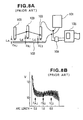
- Figs. 8A and 8B respectively, show an experimental apparatus used for carrying out the conventional pulsed arc voltage control, and a graph showing the experimental result obtained using the experimental apparatus.
- the experimental apparatus shown in Fig. 8A was arranged such that a welding source 101 produces an electric arc between a base metal 102 and an electrode 103 and, at the same time, a recorder 105 via a filter 104 records the arc voltage.
- Welding conditions utilized a reference current set to 4 A, a peak current set to 20 A, a pulse frequency set to 2 Hz, and a duty cycle set to 40%.
- the electrode 103 is shown as taking three different operation modes designated by reference characters "A", “B” and “C", respectively.
- the number of the electrode 103 used was only one. From “A” point to “B” point, welding was carried out by moving a torch (not shown) rightward in Fig. 8A over a distance of about 20 mm while moving the torch upward at a constant speed such that the arc length LA at "A" point is 0.3 mm and the arc length at "B” point is 1.0 mm. From “B” point to “C” point, the welding further continued by moving the torch rightward over a distance of about 20 mm while moving the torch downward at the constant speed so that the arc length LC at "C" point is 0.3 mm.
- the horizontal axis represents welding modes or conditions "A", “B” and “C”
- the vertical axis represents the measured voltage.
- the voltage is in a range of 10.2 to 10.8 V.
- the voltage is in a range of 10.0 to 10.6 V.
- the voltage is in a range of 10.2 to 10.8 V.
- the measured voltage is nearly constant even through the arc length varies from 0.3 to 1.0 mm. It may be safely said that the proportional relationship between the arc length and the voltage is not established.
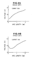
- Figs. 9A and 9B are graphs showing correlations between the arc length and the voltage that were obtained through an experiment using continuous arcs.
- welding of a copper plate was performed using a continuous arc produced by a TIG arc welding machine having a 1.6-mm-diameter tungsten electrode.
- Fig. 9A shows the experimental result obtained when the continuous arc welding was achieved at a current of 105 A.
- the horizontal axis represents the arc length and the vertical axis represents the voltage. It can be seen from Fig. 9A that the arc length and the voltage are proportional to each other and they substantially assume a linear function.
- Fig. 9B shows the experimental result obtained from the continuous arc welding achieved at a current of 14 A.
- the arc length and the voltage are proportional to each other as long as the arc length indicated by the horizontal axis is not less than 1.0 mm.
- the voltage shows an increase.
- the present inventors have reached a view that the known proportional relationship between the arc length and the voltage can be used when the welding is achieved with a relatively long arc length (larger than 1.0 mm and in a range of 2.0 mm to 5.0 mm) and at a relatively high current value (larger than 100 A), but the same relationship cannot apply when the arc length is less than 1.0 mm.
- the present invention provides a novel welding technique which can realize welding of very thin sheet metals that cannot be achieved by the conventional arc voltage control.
- a control method for an arc welding process comprising the steps of: (a) obtaining optical information from light produced from an electric arc during an arc welding process; (b) comparing the obtained optical information with reference information; (c) adjusting welding conditions on the basis of a result of comparison made between the obtained optical information and the reference information; (d) carrying out the arc welding process under the adjusted welding conditions; and (e) repeating the preceding processes (a) to (d) in the order named to thereby perform the arc welding process.
- the control method of the first invention replaces the conventional constant voltage control or constant torch height control by a position control of an electrode or a torch that is performed while adjusting welding conditions on the basis of optical information obtained from the light of an electric arc produced during an arc welding process.
- the optical information such as illuminance (also known as illumination or luminous flux density), obtained from the arc light has a good mutual relationship with the arch length or the torch height. Based on the illuminance or the like optical information, the weld control is achieved with high accuracy and reliability.
- the arc welding process is a non-consumable electrode arc welding process.
- a non-consumable electrode arc welding process which is typified by the TIG (tungsten inert-gas) arc welding
- the present invention can effectively perform welding of very thin sheet metals at low current and low voltage because a good mutual relationship established between the illuminance and the arc length has been confirmed even when the arc length is 0.25 mm. This enables a low heat exertion welding process, which can sufficiently suppress distortion of the base metal.
- the optical information comprises illuminance of the arc light.
- the optical information may include illuminance of the arc light (illuminance at all spectrums), a variation of illuminance, spectral distribution, spectral intensity and so on.
- the illuminance can be easily measured by an illuminance meter, which is readily available, so that by reducing the invention method into practice, a substantial cost increase can be suppressed.
- an arc welding apparatus comprising: a welding machine that produces an electric arc across an electrode and a base metal; an optical sensor that obtains optical information from light produced from the electric arc during an arc welding process; and a processing unit that adjusts welding conditions according to the obtained optical information.
- the optical information such as illuminance
- the weld control is carried out on the basis of the optical information such as illuminance.
- the apparatus used for achieving the weld control merely requires an optical sensor and a processing unit that are provided in addition to an existing welding machine. Accordingly, undue increase in the equipment cost can be suppressed.
- the arc welding process achieved by the arc welding machine is a non-consumable electrode arc welding process.
- a non-consumable electrode arc welding process typified by the TIG welding
- the arc welding apparatus uses optical information comprised of illuminance of the arc light because an inexpensive and readily available illuminance meter can be used. Incorporating such illuminance meter into the arc welding apparatus does not greatly increase the equipment cost.
- a TIG arc welding experimental apparatus which, as shown in Fig. 1A, is arranged to measure an electric arc 3 formed across an electrode 1 and a base metal 2 by means of an illuminance meter 4, the present inventors investigated the mutual relationship or correlation between the arc length and the illuminance.
- Fig. 1B graphically shows a relationship between the arc length and the illuminance obtained when a TIG arc welding process was performed with a welding current set at 40 A.
- the relationship between the arc length and the illuminance is represented by a linear function having a positive gradient or slope. This is because the illuminance take values of 731, 2125 and 6289 lux, respectively, when the arc length is 0.25, 1.0 and 3.0 mm.
- Fig. 1C is a graph showing a relationship between the arc length and the illuminance obtained when a TIG arc welding process was performed at a welding current of 81.25 A.
- the relationship between the arc length and the illuminance is also represented by a linear function having a positive gradient or slope. This is because the illuminance takes values of 0.2006 x 10 4 , 0.46 x 10 4 and 1.2649 x 10 4 lux, respectively, when the arc length is 0.25, 1.0 and 3.0 mm.
- Fig. 2 shows a MIG arc welding experimental apparatus used in an experiment made to determine the correlation between the distance from a base metal 7 to a torch 5 (i.e., torch height) and the illuminance (lux).
- the experimental apparatus includes an optical fiber 9a having one end thereof facing an electric arc 8 formed across a consumable electrode (wire) 6 passed through the torch 5 and the base metal 7, and an illuminance meter 9 connected to the opposite end of the optical fiber 9a for measuring illuminance of the arc light.
- Figs. 3A and 3B are graphs each showing a correlation between the torch height and the illuminance obtained using the MIG arc welding experimental apparatus when different base metals were used.
- the illuminance takes values of 56.5, 41.5 and 34.9 lux, respectively, when the torch height is 7.5, 19 and 22.5 mm. From this, the correlation between the torch height and the illuminance can be represented by a linear function having a negative gradient or slope.
- the illuminance takes values of 75, 58 and 52 lux, respectively, when the torch height is 10, 19 and 22.5 mm. From this, the correlation between the torch height and the illuminance can be also represented by a linear function having a negative gradient or slope.
- Fig. 4 is a view showing the principle of an arc welding apparatus according to the present invention.
- the arc welding apparatus 10 comprises a welding machine 14 that produces an electric arc 13 across an electrode 11 and a base metal 12, an optical sensor 15 that obtains optical information from light produced from the electric arc during an arc welding process, and a central processing unit (CPU) 21 that, on the basis of the obtained optical information, adjusts welding conditions to thereby vary the length of the arc 13 (arc length L) by lifting a torch holder 19 and a torch 20 up and down via a lift control unit 16, a lift motor 17 and a screw 18.
- CPU central processing unit
- Reference numeral 22 denotes an analog-to-digital (A/D) converter, which is provided only when conversion of an analog signal to a digital signal is necessary.
- A/D analog-to-digital
- the optical information may include illuminance of the arc light (illuminance at all spectrums), variations of illuminance, spectral distribution, spectral intensity and so on.
- illuminance of the arc light luminance at all spectrums
- variations of illuminance variations of illuminance
- spectral distribution variations of illuminance
- spectral intensity spectral intensity
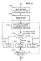
- Fig. 5 is a flowchart showing an arc welding control procedure according to the present invention.
- a single bevel groove, V-shaped groove or U-shaped groove is formed and filled with weld metal. If such groove is formed with local irregularities, a defect may occur in the form of an insufficient deposition of weld metal or an excessive deposition of weld metal.
- a defect-inducing groove (defective groove) can be found or detected through human eyes of the welding operator.
- detection of such defective groove requires a CCD camera and an image analyzer that are provided separately.
- a CCD camera and an image analyzer must be provided separately.
- a steep change will occur in the illuminance, spectral intensity or spectral distribution.
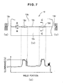
- the steep change in the illuminance may be considered to indicate the occurrence of a defective gap (defective groove). An example of such defective groove will be discussed below in detail.
- the vertical axis represents the illuminance of arc light and the horizontal axis represents the welded portion.
- the illuminance has two measured values: a first value LX1 and a second value LX2 which is much larger than the first value LX1:
- a first value LX1 and a second value LX2 which is much larger than the first value LX1:
- vertical lines drawn downward from the defective groove portions 12d shown in (b) well match in position to the welded portions having the illuminance values LX2. From this, it is confirmed that the defective groove can be detected with high accuracy in the form of a change in the illumination.
- the material of the base metal is, in many cases, difficult to discriminate visually. Accordingly, checking of the material of the base metal is not practically effected in the welding process. According to the present invention, however, since a reference voltage peculiar to each material is previously inputted in the CPU, a measured voltage deviating greatly from a selected reference value may provably indicate that the base metal is made of a material other than specified. Thus, an incorrect material can be detected.
- the present invention dexterously utilizes "optical information from the arc light", so that the invention can be applied to both the non-consumable electrode arc welding process (TIG arc welding, atomic-hydrogen arc welding and carbon arc welding) and the consumable electrode arc welding process (MIG arc welding, carbon oxide gas arc welding, electrogas arc welding, shielded arc welding and metal arc welding) so long as the arc light stands exposed during the welding process.
- TIG arc welding non-consumable electrode arc welding process
- MIG arc welding carbon oxide gas arc welding
- electrogas arc welding electrogas arc welding
- shielded arc welding shielded arc welding and metal arc welding
- TIG arc welding which is a typical of the non-consumable electrode arc welding process, can perform accurate welding of very thin sheet metals because a good mutual relationship between the illuminance and the arc length is established over the arc lengths ranging from 0.25 to 3.0 mm.
- the optical information may include various items of information or factors.
- the quantity of light and the illuminance can be easily measured by using a light-quantity meter and an illuminance meter, respectively, both of which are inexpensive and readily available. Accordingly, from the utility and economical point of view, it is reasonable to use the quantity of light or the illuminance as a weld control factor.
- the arc welding apparatus shown in Fig. 4 has been focused on the lift mechanism for the holder 19.
- the holder 19 may be attached to a robot arm for enabling three-dimensional positioning.
- the arc welding apparatus may be composed of a well-known automated welding apparatus or a semi-automatic welding apparatus, which is equipped with an optical sensor and a processing unit for processing optical information obtained from the optical sensor.
Landscapes
- Engineering & Computer Science (AREA)
- Physics & Mathematics (AREA)
- Plasma & Fusion (AREA)
- Mechanical Engineering (AREA)
- Theoretical Computer Science (AREA)
- Arc Welding In General (AREA)
Abstract
Description
Base Metal: stainless steel plate (JIS SUS 316L)
Kind of Electrode: tungsten
Electrode Diameter: 1.6 mm
Electrode Extension: 6.0 mm
Electrode Tip Angle: 30°
Electrode to Illuminance Meter Distance: 150 mm
Welding Machine: TIG arc welding machine
Welding Current: 40 A (Fig. 1B) and 81.25 A (Fig. 1C)
Base Metal: 6 mm thick aluminum plate or
12 mm thick stainless steel plate
Electrode Diameter: 1.2 mm
Electrode to Illuminance Meter Distance: 65 mm
Welding Machine: MIG arc welding machine
Welding Current: 200 A
Welding Voltage: 25 V (for aluminum plate) or
28V (for stainless steel plate)
Welding Speed: 600 mm/min
- (a) of Fig. 7 is a cross-sectional view taken along line
a-a of (b), showing a normal or
non-defective abutting portion 12c.
Claims (6)
- A control method for an arc welding process, comprising the steps of:(a) obtaining optical information from light produced from an electric arc during an arc welding process;(b) comparing the obtained optical information with reference information;(c) adjusting welding conditions on the basis of a result of comparison made between the obtained optical information and the reference information;(d) carrying out the arc welding process under the adjusted welding conditions; and(e) repeating the preceding processes (a) to (d) in the order named to thereby perform the arc welding process.
- The control method for the arc welding process according to claim 1, wherein the arc welding process is a non-consumable electrode arc welding process.
- The control method for the arc welding process according to claim 1 or 2, wherein the optical information comprises illuminance of the light from the electric arc.
- An arc welding apparatus comprising:a welding machine that produces an electric arc across an electrode and a base metal;an optical sensor that obtains optical information from light produced from the electric arc during an arc welding process; anda processing unit that adjusts welding conditions according to the obtained optical information.
- The arc welding apparatus according to claim 4, wherein the arc welding process is a non-consumable electrode arc welding process.
- The arc welding apparatus according to claim 4 or 5, wherein the optical information comprises illuminance of the light from the electric arc.
Applications Claiming Priority (3)
| Application Number | Priority Date | Filing Date | Title |
|---|---|---|---|
| JP2000373141 | 2000-12-07 | ||
| JP2000373141 | 2000-12-07 | ||
| PCT/JP2001/010575 WO2002045899A1 (en) | 2000-12-07 | 2001-12-04 | Control method of arc welding and arc welder |
Publications (2)
| Publication Number | Publication Date |
|---|---|
| EP1340576A1 true EP1340576A1 (en) | 2003-09-03 |
| EP1340576A4 EP1340576A4 (en) | 2007-12-05 |
Family
ID=18842580
Family Applications (1)
| Application Number | Title | Priority Date | Filing Date |
|---|---|---|---|
| EP01999454A Withdrawn EP1340576A4 (en) | 2000-12-07 | 2001-12-04 | Control method of arc welding and arc welder |
Country Status (5)
| Country | Link |
|---|---|
| US (1) | US6744012B2 (en) |
| EP (1) | EP1340576A4 (en) |
| CA (1) | CA2395912C (en) |
| MX (1) | MXPA02006821A (en) |
| WO (1) | WO2002045899A1 (en) |
Cited By (2)
| Publication number | Priority date | Publication date | Assignee | Title |
|---|---|---|---|---|
| CN102189314A (en) * | 2010-03-16 | 2011-09-21 | 株式会社大亨 | Arc welding control method of non-consumable electrode |
| CN103658934A (en) * | 2012-09-12 | 2014-03-26 | 株式会社大亨 | Welding power source and fixed-position welding method |
Families Citing this family (86)
| Publication number | Priority date | Publication date | Assignee | Title |
|---|---|---|---|---|
| DE10351579A1 (en) * | 2003-11-05 | 2005-06-02 | Ses-Entwicklung Gmbh | Method for checking weld seams during a welding process and an apparatus for carrying out this method |
| JP3841091B2 (en) * | 2004-07-08 | 2006-11-01 | 松下電器産業株式会社 | Consumable electrode welding method |
| US7842904B2 (en) * | 2004-10-21 | 2010-11-30 | Panasonic Corporation | Welding system and consumable electrode welding method |
| US9937577B2 (en) | 2006-12-20 | 2018-04-10 | Lincoln Global, Inc. | System for a welding sequencer |
| US9104195B2 (en) | 2006-12-20 | 2015-08-11 | Lincoln Global, Inc. | Welding job sequencer |
| US10994358B2 (en) | 2006-12-20 | 2021-05-04 | Lincoln Global, Inc. | System and method for creating or modifying a welding sequence based on non-real world weld data |
| US8927901B2 (en) * | 2008-03-17 | 2015-01-06 | Alcoa Inc. | Buried-arc welding of metal work pieces with through-the-arc seam tracking |
| US8851896B2 (en) | 2008-08-21 | 2014-10-07 | Lincoln Global, Inc. | Virtual reality GTAW and pipe welding simulator and setup |
| US9330575B2 (en) | 2008-08-21 | 2016-05-03 | Lincoln Global, Inc. | Tablet-based welding simulator |
| US8915740B2 (en) | 2008-08-21 | 2014-12-23 | Lincoln Global, Inc. | Virtual reality pipe welding simulator |
| US8884177B2 (en) | 2009-11-13 | 2014-11-11 | Lincoln Global, Inc. | Systems, methods, and apparatuses for monitoring weld quality |
| US9318026B2 (en) | 2008-08-21 | 2016-04-19 | Lincoln Global, Inc. | Systems and methods providing an enhanced user experience in a real-time simulated virtual reality welding environment |
| US9280913B2 (en) | 2009-07-10 | 2016-03-08 | Lincoln Global, Inc. | Systems and methods providing enhanced education and training in a virtual reality environment |
| US8747116B2 (en) * | 2008-08-21 | 2014-06-10 | Lincoln Global, Inc. | System and method providing arc welding training in a real-time simulated virtual reality environment using real-time weld puddle feedback |
| US8834168B2 (en) | 2008-08-21 | 2014-09-16 | Lincoln Global, Inc. | System and method providing combined virtual reality arc welding and three-dimensional (3D) viewing |
| US9196169B2 (en) | 2008-08-21 | 2015-11-24 | Lincoln Global, Inc. | Importing and analyzing external data using a virtual reality welding system |
| US8911237B2 (en) | 2008-08-21 | 2014-12-16 | Lincoln Global, Inc. | Virtual reality pipe welding simulator and setup |
| US9483959B2 (en) | 2008-08-21 | 2016-11-01 | Lincoln Global, Inc. | Welding simulator |
| US8657605B2 (en) * | 2009-07-10 | 2014-02-25 | Lincoln Global, Inc. | Virtual testing and inspection of a virtual weldment |
| CN101406980B (en) * | 2008-11-21 | 2011-04-27 | 北京工业大学 | A method of arc length control |
| US8274013B2 (en) | 2009-03-09 | 2012-09-25 | Lincoln Global, Inc. | System for tracking and analyzing welding activity |
| US9773429B2 (en) | 2009-07-08 | 2017-09-26 | Lincoln Global, Inc. | System and method for manual welder training |
| US9221117B2 (en) | 2009-07-08 | 2015-12-29 | Lincoln Global, Inc. | System for characterizing manual welding operations |
| US9011154B2 (en) | 2009-07-10 | 2015-04-21 | Lincoln Global, Inc. | Virtual welding system |
| US10748447B2 (en) | 2013-05-24 | 2020-08-18 | Lincoln Global, Inc. | Systems and methods providing a computerized eyewear device to aid in welding |
| WO2011006245A1 (en) * | 2009-07-17 | 2011-01-20 | Diversitech Equipment And Sales (1984) Ltd. | Fume extraction system with automatic fume hood positioning |
| US8569655B2 (en) | 2009-10-13 | 2013-10-29 | Lincoln Global, Inc. | Welding helmet with integral user interface |
| US9468988B2 (en) | 2009-11-13 | 2016-10-18 | Lincoln Global, Inc. | Systems, methods, and apparatuses for monitoring weld quality |
| US8284385B2 (en) * | 2009-11-13 | 2012-10-09 | Lincoln Global, Inc. | Welding arc apparel with UV activated images |
| US8569646B2 (en) | 2009-11-13 | 2013-10-29 | Lincoln Global, Inc. | Systems, methods, and apparatuses for monitoring weld quality |
| CN103025592B (en) * | 2010-06-30 | 2016-08-03 | 普拉德研究及开发股份有限公司 | Systems, methods and devices for oilfield equipment prediction and health management |
| CA2821671C (en) * | 2010-12-13 | 2018-01-09 | Edison Welding Institute, Inc. | Welding training system |
| WO2012096937A1 (en) * | 2011-01-10 | 2012-07-19 | Arcelormittal Investigacion Y Desarrollo S.L. | Method of welding nickel-aluminide |
| US10265796B2 (en) | 2011-11-17 | 2019-04-23 | Nelson Stud Welding, Inc. | Adaptively controlled short circuiting drawn-arc fastener welding |
| US20160093233A1 (en) | 2012-07-06 | 2016-03-31 | Lincoln Global, Inc. | System for characterizing manual welding operations on pipe and other curved structures |
| US9767712B2 (en) | 2012-07-10 | 2017-09-19 | Lincoln Global, Inc. | Virtual reality pipe welding simulator and setup |
| US10040143B2 (en) | 2012-12-12 | 2018-08-07 | Illinois Tool Works Inc. | Dabbing pulsed welding system and method |
| US10906114B2 (en) | 2012-12-21 | 2021-02-02 | Illinois Tool Works Inc. | System for arc welding with enhanced metal deposition |
| US10065260B2 (en) * | 2013-01-03 | 2018-09-04 | Illinois Tool Works Inc. | System and method for controlling an arc welding process |
| US9950383B2 (en) | 2013-02-05 | 2018-04-24 | Illinois Tool Works Inc. | Welding wire preheating system and method |
| US10835983B2 (en) | 2013-03-14 | 2020-11-17 | Illinois Tool Works Inc. | Electrode negative pulse welding system and method |
| US10930174B2 (en) | 2013-05-24 | 2021-02-23 | Lincoln Global, Inc. | Systems and methods providing a computerized eyewear device to aid in welding |
| US11045891B2 (en) | 2013-06-13 | 2021-06-29 | Illinois Tool Works Inc. | Systems and methods for anomalous cathode event control |
| CN105026094B (en) * | 2013-08-01 | 2017-04-26 | 希特丽格有限责任公司 | Optical device for checking the quality of welding torch electrodes |
| US20150072323A1 (en) | 2013-09-11 | 2015-03-12 | Lincoln Global, Inc. | Learning management system for a real-time simulated virtual reality welding training environment |
| US10828728B2 (en) | 2013-09-26 | 2020-11-10 | Illinois Tool Works Inc. | Hotwire deposition material processing system and method |
| US10083627B2 (en) | 2013-11-05 | 2018-09-25 | Lincoln Global, Inc. | Virtual reality and real welding training system and method |
| US9836987B2 (en) | 2014-02-14 | 2017-12-05 | Lincoln Global, Inc. | Virtual reality pipe welding simulator and setup |
| CN106233358A (en) | 2014-06-02 | 2016-12-14 | 林肯环球股份有限公司 | System and method for artificial welders training |
| US11154946B2 (en) * | 2014-06-30 | 2021-10-26 | Illinois Tool Works Inc. | Systems and methods for the control of welding parameters |
| US11198189B2 (en) | 2014-09-17 | 2021-12-14 | Illinois Tool Works Inc. | Electrode negative pulse welding system and method |
| WO2016044679A1 (en) | 2014-09-19 | 2016-03-24 | Realityworks, Inc. | Welding speed sensor |
| US10643495B2 (en) | 2014-09-19 | 2020-05-05 | Realityworks, Inc. | Welding speed pacing device |
| US11478870B2 (en) | 2014-11-26 | 2022-10-25 | Illinois Tool Works Inc. | Dabbing pulsed welding system and method |
| ITMI20142041A1 (en) * | 2014-11-27 | 2016-05-27 | Nuovo Pignone Srl | MANIPULATOR EQUIPMENT FOR PERFORMING A TIG WELDING |
| US10189106B2 (en) | 2014-12-11 | 2019-01-29 | Illinois Tool Works Inc. | Reduced energy welding system and method |
| US11370050B2 (en) | 2015-03-31 | 2022-06-28 | Illinois Tool Works Inc. | Controlled short circuit welding system and method |
| US11285559B2 (en) | 2015-11-30 | 2022-03-29 | Illinois Tool Works Inc. | Welding system and method for shielded welding wires |
| US10610946B2 (en) | 2015-12-07 | 2020-04-07 | Illinois Tool Works, Inc. | Systems and methods for automated root pass welding |
| US10675699B2 (en) | 2015-12-10 | 2020-06-09 | Illinois Tool Works Inc. | Systems, methods, and apparatus to preheat welding wire |
| US12194579B2 (en) | 2015-12-10 | 2025-01-14 | Illinois Tool Works Inc. | Systems, methods, and apparatus to preheat welding wire |
| CN108602149B (en) | 2016-03-17 | 2020-08-21 | 本田技研工业株式会社 | Welding method and device |
| EP3319066A1 (en) | 2016-11-04 | 2018-05-09 | Lincoln Global, Inc. | Magnetic frequency selection for electromagnetic position tracking |
| US20180130226A1 (en) | 2016-11-07 | 2018-05-10 | Lincoln Global, Inc. | System and method for calibrating a welding trainer |
| US10913125B2 (en) | 2016-11-07 | 2021-02-09 | Lincoln Global, Inc. | Welding system providing visual and audio cues to a welding helmet with a display |
| US10766092B2 (en) | 2017-04-18 | 2020-09-08 | Illinois Tool Works Inc. | Systems, methods, and apparatus to provide preheat voltage feedback loss protection |
| US10870164B2 (en) | 2017-05-16 | 2020-12-22 | Illinois Tool Works Inc. | Systems, methods, and apparatus to preheat welding wire |
| US10997872B2 (en) | 2017-06-01 | 2021-05-04 | Lincoln Global, Inc. | Spring-loaded tip assembly to support simulated shielded metal arc welding |
| US11524354B2 (en) | 2017-06-09 | 2022-12-13 | Illinois Tool Works Inc. | Systems, methods, and apparatus to control weld current in a preheating system |
| CA3066677C (en) | 2017-06-09 | 2023-04-04 | Illinois Tool Works Inc. | Welding assembly for a welding torch, with two contact tips and a cooling body to cool and conduct current |
| CA3066666C (en) | 2017-06-09 | 2024-10-01 | Illinois Tool Works Inc. | Contact tips with screw threads and head to enable unthreading of the screw threads comprising longitudinal slots for gas flow; welding torch with contact tips |
| US11247290B2 (en) | 2017-06-09 | 2022-02-15 | Illinois Tool Works Inc. | Systems, methods, and apparatus to preheat welding wire |
| EP3634684B1 (en) | 2017-06-09 | 2022-10-05 | Illinois Tool Works Inc. | Welding torch with a first contact tip to preheat welding wire and a second contact tip |
| US11020813B2 (en) | 2017-09-13 | 2021-06-01 | Illinois Tool Works Inc. | Systems, methods, and apparatus to reduce cast in a welding wire |
| US11475792B2 (en) | 2018-04-19 | 2022-10-18 | Lincoln Global, Inc. | Welding simulator with dual-user configuration |
| US11557223B2 (en) | 2018-04-19 | 2023-01-17 | Lincoln Global, Inc. | Modular and reconfigurable chassis for simulated welding training |
| US11213912B2 (en) * | 2018-06-25 | 2022-01-04 | Bwxt Nuclear Operations Group, Inc. | Methods and systems for monitoring a temperature of a component during a welding operation |
| EP3843933B1 (en) | 2018-08-31 | 2026-01-14 | Illinois Tool Works, Inc. | Submerged arc welding system and submerged arc welding torch to resistively preheat electrode wire |
| US11014185B2 (en) | 2018-09-27 | 2021-05-25 | Illinois Tool Works Inc. | Systems, methods, and apparatus for control of wire preheating in welding-type systems |
| JP7272784B2 (en) * | 2018-12-04 | 2023-05-12 | ファナック株式会社 | Factory environment control system |
| EP3898055A2 (en) | 2018-12-19 | 2021-10-27 | Illinois Tool Works, Inc. | Contact tip, wire preheating assembly, contact tip assembly and consumable electrode-fed welding type system |
| US12583048B2 (en) | 2019-03-29 | 2026-03-24 | Illinois Tool Works Inc. | Methods and apparatus to convert welding-type power to welding-type power and resistive preheating power |
| US12103121B2 (en) | 2019-04-30 | 2024-10-01 | Illinois Tool Works Inc. | Methods and apparatus to control welding power and preheating power |
| US11772182B2 (en) | 2019-12-20 | 2023-10-03 | Illinois Tool Works Inc. | Systems and methods for gas control during welding wire pretreatments |
| WO2022221142A1 (en) * | 2021-04-12 | 2022-10-20 | Newfrey Llc | Computer modeling for detection of discontinuities and remedial actions in joining systems |
| RU2760143C1 (en) * | 2021-04-30 | 2021-11-22 | федеральное государственное автономное образовательное учреждение высшего образования "Казанский (Приволжский) федеральный университет" (ФГАОУ ВО КФУ) | Regulation method for welding arc in the process of automated welding or surfacing using a welding positioner |
Family Cites Families (11)
| Publication number | Priority date | Publication date | Assignee | Title |
|---|---|---|---|---|
| CH129941A (en) * | 1927-12-16 | 1928-11-15 | Alexander Perrig | Method and device for regulating the arc length in electrical arc welding. |
| US3209121A (en) * | 1962-09-04 | 1965-09-28 | Union Carbide Corp | Electrode proximity control |
| US3262006A (en) * | 1963-12-27 | 1966-07-19 | Welding Research Inc | Welding control system |
| US3602687A (en) * | 1969-06-23 | 1971-08-31 | Battelle Development Corp | Arc length control |
| US4093844A (en) * | 1976-09-14 | 1978-06-06 | Arcair Company | Arc length measurement and control by optical scanning |
| US4532404A (en) * | 1983-02-01 | 1985-07-30 | Canadian Patents And Development Limited | Real time control system and process for controlling predetermined operating characteristics of a welding mechanism |
| JPS60136876A (en) | 1983-12-26 | 1985-07-20 | Hitachi Ltd | Vector processor |
| JPS60136876U (en) * | 1984-02-17 | 1985-09-11 | 三菱重工業株式会社 | Arc welding equipment |
| JP2612339B2 (en) | 1989-04-18 | 1997-05-21 | 三菱電機株式会社 | Electronic equipment housing |
| JP2857309B2 (en) | 1993-11-26 | 1999-02-17 | 株式会社神戸製鋼所 | Non-consumable electrode type automatic arc welding method |
| JPH10249526A (en) | 1997-03-07 | 1998-09-22 | Nippon Steel Corp | Rotating body TIG welding equipment |
-
2001
- 2001-12-04 MX MXPA02006821A patent/MXPA02006821A/en active IP Right Grant
- 2001-12-04 EP EP01999454A patent/EP1340576A4/en not_active Withdrawn
- 2001-12-04 WO PCT/JP2001/010575 patent/WO2002045899A1/en not_active Ceased
- 2001-12-04 CA CA002395912A patent/CA2395912C/en not_active Expired - Fee Related
- 2001-12-04 US US10/149,445 patent/US6744012B2/en not_active Expired - Fee Related
Cited By (4)
| Publication number | Priority date | Publication date | Assignee | Title |
|---|---|---|---|---|
| CN102189314A (en) * | 2010-03-16 | 2011-09-21 | 株式会社大亨 | Arc welding control method of non-consumable electrode |
| CN102189314B (en) * | 2010-03-16 | 2015-05-20 | 株式会社大亨 | Arc welding control method of non-consumable electrode |
| CN103658934A (en) * | 2012-09-12 | 2014-03-26 | 株式会社大亨 | Welding power source and fixed-position welding method |
| CN103658934B (en) * | 2012-09-12 | 2016-09-28 | 株式会社大亨 | The source of welding current and fixed-position welding method |
Also Published As
| Publication number | Publication date |
|---|---|
| US6744012B2 (en) | 2004-06-01 |
| MXPA02006821A (en) | 2002-10-23 |
| WO2002045899A1 (en) | 2002-06-13 |
| EP1340576A4 (en) | 2007-12-05 |
| CA2395912A1 (en) | 2002-06-13 |
| CA2395912C (en) | 2009-01-20 |
| US20030000931A1 (en) | 2003-01-02 |
Similar Documents
| Publication | Publication Date | Title |
|---|---|---|
| US6744012B2 (en) | Control method of arc welding and arc welder | |
| US7173215B1 (en) | Method for evaluating and/or comparing welding consumables | |
| US20100133239A1 (en) | Submerged Arc Narrow Gap Welding With Oscillating Electrode | |
| JP6052798B2 (en) | Abnormality monitoring device for automatic welding machine | |
| KR20180121944A (en) | Arc tracking welding method and arc tracking welding device | |
| KR20190068579A (en) | Method of detecting misalignment amount in arc tracking welding | |
| GB1584017A (en) | Regulating the power of an arc-welding burner | |
| JP3943380B2 (en) | Arc welding control method and arc welding apparatus | |
| Barborak et al. | " Through-arc" process monitoring: techniques for control of automated gas metal arc welding | |
| EP0824985A3 (en) | Consumable electrode type arc welding method and device | |
| JP2553915B2 (en) | Automatic welding method for cylindrical containers | |
| EP0314799A1 (en) | Path correction method for automatic welding machine | |
| EP0049037B1 (en) | Method and apparatus for the narrow gap welding of thick tubes | |
| JP3198816B2 (en) | First layer welding method for single-sided butt welding of fixed pipes | |
| JP3198815B2 (en) | First layer welding method for single-sided butt welding of fixed pipes | |
| JP2540288B2 (en) | Membrane automatic welding equipment | |
| US4876432A (en) | Method for controlling a penetration bead | |
| KR100313484B1 (en) | Optimum fill area control method according to variation of groove area by using constant voltage characteristic | |
| Cook et al. | Computer-based analysis of arc welding signals for tracking and process control | |
| CN117680879B (en) | Welding seam cross section molten pool solidification in-situ observation equipment and method | |
| JP3166511B2 (en) | Narrow butt welding method for fixed pipe | |
| JP2721250B2 (en) | Groove copying method and apparatus | |
| JP3235506B2 (en) | Welding method by arc welding | |
| EP1419027B1 (en) | Process and device for welding arc control by determining the instantaneous current and voltage | |
| JPH067991B2 (en) | Automatic welding equipment |
Legal Events
| Date | Code | Title | Description |
|---|---|---|---|
| PUAI | Public reference made under article 153(3) epc to a published international application that has entered the european phase |
Free format text: ORIGINAL CODE: 0009012 |
|
| 17P | Request for examination filed |
Effective date: 20020723 |
|
| AK | Designated contracting states |
Kind code of ref document: A1 Designated state(s): AT BE CH CY DE DK ES FI FR GB GR IE IT LI LU MC NL PT SE TR |
|
| AX | Request for extension of the european patent |
Extension state: AL LT LV MK RO SI |
|
| RBV | Designated contracting states (corrected) |
Designated state(s): AT BE CH DE FR GB LI |
|
| A4 | Supplementary search report drawn up and despatched |
Effective date: 20071102 |
|
| 17Q | First examination report despatched |
Effective date: 20080707 |
|
| STAA | Information on the status of an ep patent application or granted ep patent |
Free format text: STATUS: THE APPLICATION IS DEEMED TO BE WITHDRAWN |
|
| 18D | Application deemed to be withdrawn |
Effective date: 20100217 |