EP1338819A2 - Dynamic damper and propeller shaft - Google Patents
Dynamic damper and propeller shaft Download PDFInfo
- Publication number
- EP1338819A2 EP1338819A2 EP02020159A EP02020159A EP1338819A2 EP 1338819 A2 EP1338819 A2 EP 1338819A2 EP 02020159 A EP02020159 A EP 02020159A EP 02020159 A EP02020159 A EP 02020159A EP 1338819 A2 EP1338819 A2 EP 1338819A2
- Authority
- EP
- European Patent Office
- Prior art keywords
- outer pipe
- dynamic damper
- elastic body
- weight
- convex portions
- Prior art date
- Legal status (The legal status is an assumption and is not a legal conclusion. Google has not performed a legal analysis and makes no representation as to the accuracy of the status listed.)
- Granted
Links
Images

Classifications
-
- F—MECHANICAL ENGINEERING; LIGHTING; HEATING; WEAPONS; BLASTING
- F16—ENGINEERING ELEMENTS AND UNITS; GENERAL MEASURES FOR PRODUCING AND MAINTAINING EFFECTIVE FUNCTIONING OF MACHINES OR INSTALLATIONS; THERMAL INSULATION IN GENERAL
- F16F—SPRINGS; SHOCK-ABSORBERS; MEANS FOR DAMPING VIBRATION
- F16F15/00—Suppression of vibrations in systems; Means or arrangements for avoiding or reducing out-of-balance forces, e.g. due to motion
- F16F15/10—Suppression of vibrations in rotating systems by making use of members moving with the system
- F16F15/14—Suppression of vibrations in rotating systems by making use of members moving with the system using masses freely rotating with the system, i.e. uninvolved in transmitting driveline torque, e.g. rotative dynamic dampers
- F16F15/1407—Suppression of vibrations in rotating systems by making use of members moving with the system using masses freely rotating with the system, i.e. uninvolved in transmitting driveline torque, e.g. rotative dynamic dampers the rotation being limited with respect to the driving means
- F16F15/1414—Masses driven by elastic elements
- F16F15/1435—Elastomeric springs, i.e. made of plastic or rubber
- F16F15/1442—Elastomeric springs, i.e. made of plastic or rubber with a single mass
-
- F—MECHANICAL ENGINEERING; LIGHTING; HEATING; WEAPONS; BLASTING
- F16—ENGINEERING ELEMENTS AND UNITS; GENERAL MEASURES FOR PRODUCING AND MAINTAINING EFFECTIVE FUNCTIONING OF MACHINES OR INSTALLATIONS; THERMAL INSULATION IN GENERAL
- F16F—SPRINGS; SHOCK-ABSORBERS; MEANS FOR DAMPING VIBRATION
- F16F15/00—Suppression of vibrations in systems; Means or arrangements for avoiding or reducing out-of-balance forces, e.g. due to motion
- F16F15/10—Suppression of vibrations in rotating systems by making use of members moving with the system
Definitions
- the present invention relates to a dynamic damper and a propeller shaft.
- dampers which reduce vibration of an automobile driving power transmitting member, such as a propeller shaft, in order to reduce vehicle vibration and mechanical noise.
- Such dynamic dampers include an outer pipe, a weight disposed inside the outer pipe and an elastic body disposed between the outer pipe and the weight. This dynamic damper is pressed into a hollow shaft constituting the propeller shaft and is fixed thereto.
- an elastic body is disposed in an annular space between an outer pipe and a weight, and a rod-like elastic interposed portion is provided so as to extend in the radius direction at each of plural positions (five positions) in the circumferential direction of the annular space.
- An object of the present invention is to provide a dynamic damper having improved durability and reliability.
- Another object of the present invention is to press a dynamic damper into a hollow shaft easily, to be fixed thereto stably.
- a dynamic damper comprising an outer pipe, a weight disposed inside the outer pipe and an elastic body interposed between the outer pipe and the weight.
- Convex portions protruded in the direction of the inside diameter are provided at a plurality of positions along the circumferential direction of the outer pipe so as to hold the elastic body by sandwiching the outer circumferential portion of the elastic body between the adjacent convex portions.
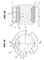
- Reference numeral 10 in FIGS. 1A and 1B denotes a dynamic damper 10, which is pressed into a hollow shaft 2 of an automobile propeller shaft 1 and disposed at a predetermined position thereof in the axial direction.
- the dynamic damper 10 reduces vibration of the propeller shaft 1 so as to reduce vehicle body vibration and mechanical noise.
- the dynamic damper 10 comprises an outer pipe 20, a weight 30 and an elastic body 40.
- the outer pipe 20 is formed by bending a metallic pipe such as thin steel pipe in the form of an irregularly shaped cylinder.
- This outer pipe 20 contains convex portions 21 protruded in the direction of its inside diameter at a plurality of positions (5 positions in this specification) along the circumferential direction. More specifically, in the outer pipe 20, the convex portions 21 are formed by bending the plural portions along the circumferential direction of a round pipe in the direction of the inside direction with a press while remaining portions are kept as circular portions 22 (circular portion 22 having substantially the same curvature of a hollow shaft 2). An end face of the convex portion 21 of the outer pipe 20 acts as a round pressing face 21A to the outer circumferential portion of an elastic body 40.
- the outside diameter of the outer pipe 20 under the free state formed by the circular portions 22 is set larger than the inside diameter of the hollow shaft 2. The outside diameter can be contracted elastically from the free state due to the elastic distortion characteristic possessed by the bent portion of the convex portion 21.
- the weight 30 is formed of a metallic rod such as steel rod in the form of a short cylinder, such as a circular cylinder.
- the weight 30 has annular grooves 31 provided in the entire circumference for loading the elastic body 40.
- the weight 30 is disposed inside the outer pipe 20 coaxially with the outer pipe 20.
- the weight 30 is wider than the outer pipe 20 (Fig. 1B).
- the elastic body 40 is formed in an annular form and is loaded on the entire circumference of the annular groove 31 in the weight 30 between the outer pipe 20 and the weight 30.
- the outer circumference of the elastic body 40 is a circular face continuous along the entire circumference, which is larger than the outside diameter of the weight 30.
- the elastic body 40 is formed of synthetic rubber and is bonded to the outer pipe 20 and the weight 30 by vulcanizing.
- the dynamic damper 10 holds the elastic body 40 by sandwiching the elastic body 40 on the weight 30 with the end pressing faces 21A of the convex portion 21 of the outer pipe 20 from the radiation direction. Also, the dynamic damper 10 sandwiches the outer peripheral portion 41 of the elastic body 40 between the end pressing faces 21A in the circumferential direction, of the convex portions 21 adjacent in the circumferential direction of the outer pipe 20. The end pressing face 21A of each convex portion 21 is buried in a predetermined depth in the outer peripheral portion 41 of the elastic body 40. The outer peripheral portion 41A is sandwiched between the end pressing faces 21A of the convex portion 21.
- the elastic body 40 is formed integrally by pouring rubber into a mold in which the outer pipe 20 and the weight 30 are disposed.
- the elastic body 40 may be formed separately and subsequently be bonded to the outer pipe 20 and/or the weight 30.
- the present embodiment has the following operations.
- the durability and reliability of the dynamic damper can be improved. Further, according to the present invention, the dynamic damper can be pressed into the hollow shaft easily and fixed thereto in a stable condition.
Landscapes
- Engineering & Computer Science (AREA)
- General Engineering & Computer Science (AREA)
- Physics & Mathematics (AREA)
- Acoustics & Sound (AREA)
- Aviation & Aerospace Engineering (AREA)
- Mechanical Engineering (AREA)
- Motor Power Transmission Devices (AREA)
- Shafts, Cranks, Connecting Bars, And Related Bearings (AREA)
- Vibration Prevention Devices (AREA)
Abstract
Description
The drawings
Claims (5)
- A dynamic damper comprising an outer pipe, a weight disposed inside the outer pipe and an elastic body interposed between the outer pipe and the weight,
wherein convex portions protruded in the direction of the inside diameter are provided at a plurality of positions along the circumferential direction of the outer pipe so as to hold the elastic body by sandwiching the outer circumferential portion of the elastic body between the adjacent convex portions. - The dynamic damper according to claim 1 wherein the contact face of the convex portion with the outer peripheral portion of the elastic body is formed in the form of a round face.
- The dynamic damper according to claim 1 wherein the weight is disposed inside the outer pipe and coaxially with the outer pipe.
- The dynamic damper according to any one of claims 1 to 3 wherein the outer pipe is bent in the direction of the inside diameter at a plurality of portions along the circumferential direction so as to form the convex portions.
- A propeller shaft wherein the outer pipe of the dynamic damper according to any one of claims 1 to 4 is pressed into and fixed to a hollow shaft.
Applications Claiming Priority (2)
| Application Number | Priority Date | Filing Date | Title |
|---|---|---|---|
| JP2002047002A JP3897609B2 (en) | 2002-02-22 | 2002-02-22 | Dynamic damper and propeller shaft |
| JP2002047002 | 2002-02-22 |
Publications (3)
| Publication Number | Publication Date |
|---|---|
| EP1338819A2 true EP1338819A2 (en) | 2003-08-27 |
| EP1338819A3 EP1338819A3 (en) | 2004-07-28 |
| EP1338819B1 EP1338819B1 (en) | 2006-05-17 |
Family
ID=27655367
Family Applications (1)
| Application Number | Title | Priority Date | Filing Date |
|---|---|---|---|
| EP02020159A Expired - Lifetime EP1338819B1 (en) | 2002-02-22 | 2002-09-09 | Dynamic damper and propeller shaft |
Country Status (4)
| Country | Link |
|---|---|
| US (1) | US7044276B2 (en) |
| EP (1) | EP1338819B1 (en) |
| JP (1) | JP3897609B2 (en) |
| DE (1) | DE60211467T2 (en) |
Families Citing this family (13)
| Publication number | Priority date | Publication date | Assignee | Title |
|---|---|---|---|---|
| JP4421500B2 (en) * | 2005-03-23 | 2010-02-24 | 倉敷化工株式会社 | Vibration isolator |
| US7681559B2 (en) * | 2006-12-21 | 2010-03-23 | Eaton Corporation | Torsion damping mechanism for a supercharger |
| US8342058B2 (en) * | 2007-06-28 | 2013-01-01 | Hillsdale Automotive, Llc | Recessed belt damper |
| JP4898599B2 (en) * | 2007-08-29 | 2012-03-14 | 株式会社ショーワ | Propeller shaft |
| US8167730B2 (en) * | 2009-09-21 | 2012-05-01 | Gkn Driveline North America, Inc. | Tuned absorber |
| DE102013106291B4 (en) * | 2013-06-17 | 2015-03-26 | Trelleborgvibracoustic Gmbh | vibration absorber |
| DE102016120801A1 (en) * | 2016-11-01 | 2018-05-03 | Henniges Automotive Gmbh & Co. Kg | Inner tube grinder for arranging within a shaft, in particular a drive shaft |
| JP6936051B2 (en) * | 2017-06-06 | 2021-09-15 | Nok株式会社 | Dynamic damper |
| JP6917199B2 (en) * | 2017-06-06 | 2021-08-11 | Nok株式会社 | Dynamic damper |
| DE102017217987A1 (en) | 2017-10-10 | 2019-04-11 | Martin Schmid | vibration absorber |
| US10677312B2 (en) * | 2018-02-15 | 2020-06-09 | General Electric Company | Friction shaft damper for axial vibration mode |
| JP7359128B2 (en) | 2020-10-28 | 2023-10-11 | トヨタ自動車株式会社 | dynamic damper |
| JP7327352B2 (en) * | 2020-10-28 | 2023-08-16 | トヨタ自動車株式会社 | dynamic damper |
Family Cites Families (23)
| Publication number | Priority date | Publication date | Assignee | Title |
|---|---|---|---|---|
| US3075406A (en) * | 1961-07-13 | 1963-01-29 | Gen Motors Corp | Propeller shaft damper |
| US4223565A (en) * | 1976-12-11 | 1980-09-23 | Honda Giken Kogyo Kabushiki Kaisha | Device for attenuating vibrations in a drive shaft of a motor vehicle |
| DE2747225C2 (en) * | 1977-10-21 | 1982-04-22 | Dr.Ing.H.C. F. Porsche Ag, 7000 Stuttgart | Drive unit elastically mounted in a motor vehicle |
| DE2922585B1 (en) * | 1979-06-02 | 1980-12-11 | Krupp Ag Huettenwerke | Vibration absorber for resonance vibrations of rotating bodies |
| DE3535286A1 (en) * | 1985-10-03 | 1987-04-09 | Opel Adam Ag | TURNING VIBRATION DETECTOR FOR A DRIVE SHAFT |
| US5188002A (en) * | 1988-07-25 | 1993-02-23 | Woco Franz-Josef Wolf & Co. | Torsional vibration damper |
| DE3940365A1 (en) * | 1989-12-06 | 1991-06-13 | Bayerische Motoren Werke Ag | Torsional vibration absorber for vehicle drive shafts - has hub ring enclosed by rotating ring with sprung pieces between |
| DE4121746C2 (en) * | 1991-07-01 | 1996-02-22 | Wolf Woco & Co Franz J | Tilger |
| JP2599059B2 (en) * | 1991-11-25 | 1997-04-09 | 東海ゴム工業株式会社 | Dynamic damper for hollow drive shaft |
| DE4201049C2 (en) * | 1992-01-17 | 1995-11-02 | Freudenberg Carl Fa | Speed-adaptive torsional vibration damper |
| DE4315483C2 (en) * | 1993-05-10 | 1996-11-28 | Freudenberg Carl Fa | Torsional vibration damper |
| US5460574A (en) * | 1993-08-31 | 1995-10-24 | Trw Inc. | Variable length shaft assembly with a lash bushing |
| JP3753191B2 (en) * | 1995-04-24 | 2006-03-08 | 株式会社ショーワ | Propeller shaft dynamic damper mounting structure |
| JP3698217B2 (en) * | 1995-06-27 | 2005-09-21 | 株式会社ショーワ | Dynamic damper structure of propeller shaft |
| JP3815696B2 (en) * | 1995-12-15 | 2006-08-30 | 株式会社ショーワ | Propeller shaft dynamic damper structure |
| DE19726293A1 (en) * | 1997-06-20 | 1998-12-24 | Contitech Formteile Gmbh | Hollow drive shaft with integrated vibration damper |
| DE19733478B4 (en) * | 1997-08-02 | 2006-03-23 | Daimlerchrysler Ag | Vibration damper for a tubular cardan shaft |
| EP1128086A2 (en) * | 2000-02-28 | 2001-08-29 | Tokai Rubber Industries, Ltd. | Vibration-damping device for vehicles |
| JP2001260681A (en) * | 2000-03-15 | 2001-09-26 | Tokai Rubber Ind Ltd | Dynamic damper and propeller shaft |
| US20020193168A1 (en) * | 2000-08-29 | 2002-12-19 | Kazuoki Hosooka | Propeller shaft |
| JP2002168291A (en) * | 2000-11-29 | 2002-06-14 | Daihatsu Motor Co Ltd | Dynamic damper system |
| DE10142822A1 (en) * | 2001-08-22 | 2003-03-27 | Woco Avs Gmbh | Innentilger |
| US6560837B1 (en) * | 2002-07-31 | 2003-05-13 | The Gates Corporation | Assembly device for shaft damper |
-
2002
- 2002-02-22 JP JP2002047002A patent/JP3897609B2/en not_active Expired - Fee Related
- 2002-09-09 DE DE60211467T patent/DE60211467T2/en not_active Expired - Lifetime
- 2002-09-09 EP EP02020159A patent/EP1338819B1/en not_active Expired - Lifetime
- 2002-09-10 US US10/238,210 patent/US7044276B2/en not_active Expired - Fee Related
Also Published As
| Publication number | Publication date |
|---|---|
| DE60211467T2 (en) | 2006-12-07 |
| DE60211467D1 (en) | 2006-06-22 |
| EP1338819B1 (en) | 2006-05-17 |
| JP3897609B2 (en) | 2007-03-28 |
| US20030159899A1 (en) | 2003-08-28 |
| JP2003247595A (en) | 2003-09-05 |
| EP1338819A3 (en) | 2004-07-28 |
| US7044276B2 (en) | 2006-05-16 |
Similar Documents
| Publication | Publication Date | Title |
|---|---|---|
| US7044276B2 (en) | Dynamic damper and propeller shaft | |
| US6725985B2 (en) | Dynamic damper and propeller shaft | |
| EP1729045B1 (en) | Sealing device for reciprocating shaft | |
| KR101275951B1 (en) | Ball joint | |
| JP2647814B2 (en) | Bush bearings used in the traveling mechanism of an automobile that receive loads in the radial and axial directions | |
| US6736246B2 (en) | Dynamic damper and propeller shaft | |
| WO2017033899A1 (en) | Cylindrical elastic coupling device for axle arms | |
| US6966413B2 (en) | Dynamic damper and propeller shaft | |
| KR101361087B1 (en) | Sealing device | |
| US20060001207A1 (en) | Elastomeric bush bearing with improved torsion characteristic | |
| JP2001099218A (en) | Strut mount | |
| CN1897416B (en) | Actuator, in particular for a motor vehicle | |
| WO2013058400A1 (en) | End support device for control cable | |
| US7010843B2 (en) | Manufacturing method for dynamic damper | |
| JP2005133917A (en) | Isolation pulley | |
| EP3812608B1 (en) | Mount and method for assembling a mount | |
| KR102440702B1 (en) | Mount for vehicle | |
| JP3507558B2 (en) | Rotary axis vibration control device and rotary axis | |
| JPH0921438A (en) | Radial bearing | |
| JP2003206970A (en) | Cylindrical vibration isolator | |
| JPH0738736Y2 (en) | Centering bush | |
| US20230099834A1 (en) | Bearing and a method for producing a bearing | |
| CN113883177B (en) | Bearing floating assembly for steering mechanism and steering mechanism | |
| US20250207649A1 (en) | Electromechanically actuatable brake piston assembly | |
| JPH0728220U (en) | Bearing devices for vehicle propeller shafts |
Legal Events
| Date | Code | Title | Description |
|---|---|---|---|
| PUAI | Public reference made under article 153(3) epc to a published international application that has entered the european phase |
Free format text: ORIGINAL CODE: 0009012 |
|
| AK | Designated contracting states |
Designated state(s): AT BE BG CH CY CZ DE DK EE ES FI FR GB GR IE IT LI LU MC NL PT SE SK TR |
|
| AX | Request for extension of the european patent |
Extension state: AL LT LV MK RO SI |
|
| PUAL | Search report despatched |
Free format text: ORIGINAL CODE: 0009013 |
|
| AK | Designated contracting states |
Kind code of ref document: A3 Designated state(s): AT BE BG CH CY CZ DE DK EE ES FI FR GB GR IE IT LI LU MC NL PT SE SK TR |
|
| AX | Request for extension of the european patent |
Extension state: AL LT LV MK RO SI |
|
| RIC1 | Information provided on ipc code assigned before grant |
Ipc: 7F 16F 7/108 A |
|
| 17P | Request for examination filed |
Effective date: 20040901 |
|
| AKX | Designation fees paid |
Designated state(s): DE GB |
|
| 17Q | First examination report despatched |
Effective date: 20050427 |
|
| GRAP | Despatch of communication of intention to grant a patent |
Free format text: ORIGINAL CODE: EPIDOSNIGR1 |
|
| GRAS | Grant fee paid |
Free format text: ORIGINAL CODE: EPIDOSNIGR3 |
|
| GRAA | (expected) grant |
Free format text: ORIGINAL CODE: 0009210 |
|
| AK | Designated contracting states |
Kind code of ref document: B1 Designated state(s): DE GB |
|
| REG | Reference to a national code |
Ref country code: GB Ref legal event code: FG4D |
|
| REF | Corresponds to: |
Ref document number: 60211467 Country of ref document: DE Date of ref document: 20060622 Kind code of ref document: P |
|
| PLBE | No opposition filed within time limit |
Free format text: ORIGINAL CODE: 0009261 |
|
| STAA | Information on the status of an ep patent application or granted ep patent |
Free format text: STATUS: NO OPPOSITION FILED WITHIN TIME LIMIT |
|
| 26N | No opposition filed |
Effective date: 20070220 |
|
| PGFP | Annual fee paid to national office [announced via postgrant information from national office to epo] |
Ref country code: DE Payment date: 20150902 Year of fee payment: 14 Ref country code: GB Payment date: 20150909 Year of fee payment: 14 |
|
| REG | Reference to a national code |
Ref country code: DE Ref legal event code: R119 Ref document number: 60211467 Country of ref document: DE |
|
| GBPC | Gb: european patent ceased through non-payment of renewal fee |
Effective date: 20160909 |
|
| PG25 | Lapsed in a contracting state [announced via postgrant information from national office to epo] |
Ref country code: DE Free format text: LAPSE BECAUSE OF NON-PAYMENT OF DUE FEES Effective date: 20170401 Ref country code: GB Free format text: LAPSE BECAUSE OF NON-PAYMENT OF DUE FEES Effective date: 20160909 |