EP1338786A1 - Air intake device of internal combustion enginge - Google Patents
Air intake device of internal combustion enginge Download PDFInfo
- Publication number
- EP1338786A1 EP1338786A1 EP03003597A EP03003597A EP1338786A1 EP 1338786 A1 EP1338786 A1 EP 1338786A1 EP 03003597 A EP03003597 A EP 03003597A EP 03003597 A EP03003597 A EP 03003597A EP 1338786 A1 EP1338786 A1 EP 1338786A1
- Authority
- EP
- European Patent Office
- Prior art keywords
- air cleaner
- air
- case
- intake device
- cleaner body
- Prior art date
- Legal status (The legal status is an assumption and is not a legal conclusion. Google has not performed a legal analysis and makes no representation as to the accuracy of the status listed.)
- Granted
Links
Images


Classifications
-
- F—MECHANICAL ENGINEERING; LIGHTING; HEATING; WEAPONS; BLASTING
- F02—COMBUSTION ENGINES; HOT-GAS OR COMBUSTION-PRODUCT ENGINE PLANTS
- F02M—SUPPLYING COMBUSTION ENGINES IN GENERAL WITH COMBUSTIBLE MIXTURES OR CONSTITUENTS THEREOF
- F02M35/00—Combustion-air cleaners, air intakes, intake silencers, or induction systems specially adapted for, or arranged on, internal-combustion engines
- F02M35/02—Air cleaners
- F02M35/024—Air cleaners using filters, e.g. moistened
-
- F—MECHANICAL ENGINEERING; LIGHTING; HEATING; WEAPONS; BLASTING
- F02—COMBUSTION ENGINES; HOT-GAS OR COMBUSTION-PRODUCT ENGINE PLANTS
- F02M—SUPPLYING COMBUSTION ENGINES IN GENERAL WITH COMBUSTIBLE MIXTURES OR CONSTITUENTS THEREOF
- F02M35/00—Combustion-air cleaners, air intakes, intake silencers, or induction systems specially adapted for, or arranged on, internal-combustion engines
- F02M35/02—Air cleaners
- F02M35/04—Air cleaners specially arranged with respect to engine, to intake system or specially adapted to vehicle; Mounting thereon ; Combinations with other devices
-
- F—MECHANICAL ENGINEERING; LIGHTING; HEATING; WEAPONS; BLASTING
- F05—INDEXING SCHEMES RELATING TO ENGINES OR PUMPS IN VARIOUS SUBCLASSES OF CLASSES F01-F04
- F05C—INDEXING SCHEME RELATING TO MATERIALS, MATERIAL PROPERTIES OR MATERIAL CHARACTERISTICS FOR MACHINES, ENGINES OR PUMPS OTHER THAN NON-POSITIVE-DISPLACEMENT MACHINES OR ENGINES
- F05C2225/00—Synthetic polymers, e.g. plastics; Rubber
- F05C2225/08—Thermoplastics
Definitions
- the present invention relates in general to air intake devices of internal combustion engines, and more particularly to the air intake devices of a type that includes an air cleaner. More specifically, the present invention is concerned with the air intake devices of a compact type suitable for use in a limited space defined above the engine in an engine room of a motor vehicle.
- the air intake devices of such space saving type are shown in Laid-open Japanese Patent Applications (Tokkaihei) 10-266913 and 2000-323842.
- an object of the present invention to provide an air intake device of an internal combustion engine, that fulfills a satisfied space saving in the engine room while exhibiting a satisfied air intake effect.
- an air intake device for use with an internal combustion engine, which comprises an air cleaner case adapted to be mounted on the engine to extend longitudinally along an upper wall of the engine; an opening formed in a longitudinal end portion of a bottom wall of the air cleaner case; an air cleaner body having an open end connected to the opening of the bottom wall of the air cleaner case thereby to communicate an interior of the air cleaner body with that of the air cleaner case; and an air cleaner element put between the air cleaner body and the air cleaner case in a manner to extend across the opening of the bottom wall of the air cleaner case.
- an air intake device for use with an internal combustion engine, which comprises an elongate air cleaner case adapted to be mounted on the engine, the air cleaner case having a given end portion that extends beyond one longitudinal end of the engine; an opening formed in the given end portion of the elongate air cleaner case; an air cleaner body having an open end, the air cleaner body being pivotally connected to the given end portion of the air cleaner case, so that the air cleaner body is pivotal between a fitted position wherein the air cleaner body is tightly fitted to the given end portion thereby to connect the open end of the air cleaner body with the opening of the given end portion of the air cleaner case and a released position wherein the air cleaner body is separated from given end portion; a clamp that detachably binds the air cleaner body and the air cleaner case together; a flange formed around the open end of the air cleaner body; and an air cleaner element put on the flange, so that when the air cleaner body assumes the fitted position, the air cleaner element is put between the air
- Engine 1 is of a four cylinder in-line type, used for a FF type (viz., front engine and front drive type) motor vehicle and transversely mounted in an engine room of the vehicle.
- FF type front engine and front drive type
- engine 1 comprises generally a cylinder block 2 having cylinders, a cylinder head 3 mounted on cylinder block 2, a cylinder head cover 4 put on cylinder head 3, an oil pan 5 mounted below cylinder block 2, an intake manifold mounted on a hidden side of cylinder head 3, an exhaust manifold 6 mounted on this side of cylinder block 3 and a catalytic converter 7 connected to exhaust manifold 6.
- engine 1 shown in Fig. 1 is taken from a forward position of an associated motor vehicle.
- a left part of the engine will be referred to "front part” and a right part of the same will be referred to "rear part”.
- air cleaner 11 is tightly mounted on an upper part of cylinder head cover 4 through four bolts 15. As shown, air cleaner 11 has a substantially flat structure and has a portion that extends rearward from the rear end of engine 1.
- cylinder head 3 of engine 1 is equipped with a DOHC type (viz., double over head cam type) valve operating mechanism.
- DOHC type viz., double over head cam type
- cylinder head cover 4 is mounted on cylinder head 3, that is constructed of a reinforced hard plastic, aluminum, aluminum alloy or the like.
- air cleaner 11 is rectangular in shape, having a width generally the same as that of cylinder head cover 4. Cylinder head cover 4 is formed at a front end portion thereof with an oil pouring opening 12. As is seen, air cleaner 11 covers entirely the upper part of cylinder head cover 4 except a part that surrounds oil pouring opening 12.
- an intake manifold 13 is mounted to cylinder head 3 on a side opposite to the side to which the above-mentioned exhaust manifold 6 is mounted. That is, when mounted in a motor vehicle, the side of cylinder head 3 to which the intake manifold 13 is mounted faces rearward of the associated motor vehicle.
- Intake manifold 13 is constructed of a reinforced hard plastic and has four air intake branches united together.
- An air collection depressed part 14 is integrally defined by air cleaner 11, which is to be connected to the above-mentioned intake manifold 13. As will be described in detail hereinafter, to air collection depressed part 14, there is connected a plastic cover 35. Two bolts 16 are used for connecting air cleaner 11 to intake manifold 13.
- air cleaner 11 generally comprises an elongate air cleaner case 21 that is tightly mounted on the upper portion of engine 1, an air cleaner body 22 that is mounted to a bottom wall of air cleaner case 21 and an air cleaner element 23 that is put between air cleaner case 21 and air cleaner body 22.
- air cleaner body 22 is mounted to a rear end portion of the bottom wall of air cleaner case 21.
- Air cleaner case 21 comprises a lower case 24 and an upper case 25 which are detachably coupled together to constitute a hollow structure. Upper case 25 is longer than lower case 24 for the purpose which will become apparent as the description proceeds. Lower case 24 is fixed to cylinder head cover 4 through the above-mentioned bolts 15. Upper case 25 is mounted on lower case 24 through five bolts 26. As seen, air cleaner case 21 is shaped substantially flat.
- air cleaner element 23 is shaped rectangular and comprises a pleated filter material 27 that is disposed on a rectangular seal member 28.
- Seal member 28 is made of a flexible urethane foam or the like. It is to be noted that in the illustrated embodiment the interior of air cleaner body 22 constitutes an upstream side (or dust side) of air cleaner element 23 and the interior of air cleaner case 21 constitutes a downstream side (or clean side) of the element 23.
- lower case 24 is shorter than upper case 25.
- lower case 24 is mounted on the entirely mounted on the given portion of cylinder head cover 4. Accordingly, when mounted on lower case 24, the rear end portion of upper case 25 projects rearward (viz., rightward as viewed in Fig. 1) from the rear end of lower case 24, so that the bottom wall of the projected part of upper case 25 is exposed to the outside facing downward. As shown in Fig. 5, the exposed bottom wall is formed with a rectangular opening 33.
- the above-mentioned air cleaner body 22 is connected to the rectangular opening 33 of the exposed bottom wall of upper case 25.
- the bottom wall of upper case 25 is formed with larger and smaller rectangular openings 32 and 33 which are partitioned by a beam 31. It is to be noted that two inner spaces defined below these two openings 32 and 33 are merged with each other through openings of a grid structure 31a defined below beam 31.
- larger rectangular opening 32 is closed by lower case 24 of air cleaner case 21 (see Figs. 1 and 3), and smaller rectangular opening 33 is connected to an upper open end 22b of air cleaner body 22 (see Fig. 3).
- the above-mentioned lower case 24 and air cleaner body 22 are both constructed of a reinforced hard plastic.
- upper case 25 is constructed of a reinforced hard plastic. It is to be noted that upper case 25 shown in the drawing has the cover (35) for air collection depressed part 14 removed.
- the cover (35) is also constructed of a reinforced hard plastic and connected to air collection depressed part 14 through a welding or the like.
- air collection depressed part 14 constitutes an air collection space (14) to which upper open ends of the four air intake branches of intake manifold 13 are exposed (see Fig. 2).
- FIGs. 5 and 6 that show the interior of upper case 25
- air collection space 14 is separated from the main interior space of larger rectangular opening 32 by means of a partition wall 14a.
- This partition wall 14a is formed with a cylindrical opening 37 through which air collection space 14 and the main interior space are communicated.
- cylindrical opening 37 is equipped with a throttle device 41 which selectively opens and closes the opening 37.
- cleaned air from air cleaner element 23 is led in order into the smaller chamber 33 of air cleaner case 21, the larger chamber 32 of the same through the openings of grid structure 31a, air collection space 14 through cylindrical opening 37 (viz., throttle device 41), and into the four air intake branches of intake manifold 13 through four cylindrical portions 36. Because air collection space 14 has a smaller capacity as compared with the larger chamber 32, improved transient responsibility is expected by the associated engine.
- cover 35 for air collection space (14) has a smoothly curved upper wall 35a for smoothing the cleaned intake air flowing from cylindrical opening 37 toward the four air intake branches of intake manifold 13.
- a throttle body 41 that formed the above-mentioned throttle device (41) is installed in the larger chamber 32 of air cleaner case 21.
- Throttle body 41 has a cylindrical air passage 44 in which a throttle valve 43 driven by an electric motor 42 is operatively installed.
- an upper end of cylindrical air passage 44 is fitted to the above-mentioned cylindrical opening 37.
- three bolts 46 are used which are engaged with threaded bores (no numerals) formed in a boss portion 45 of upper case 25 by which cylindrical opening 37 is defined.
- a circular gasket 49 For achieving a seal between upper end of cylindrical air passage 44 and cylindrical opening 37, there is used a circular gasket 49.
- a lower open end of cylindrical air passage 44 is exposed to the interior of the larger rectangular chamber 32 of air cleaner case 21.
- Electric motor 42 has a projected connector portion 47 (see Fig. 2) exposed to the upper surface of upper case 25 through a circular opening 48 that is provided in an upper wall of upper case near cylindrical opening 37.
- projected connector portion 47 has a cylindrical ridge at a root portion thereof.
- a circular gasket 50 For achieving a seal between the cylindrical ridge and circular opening 48, there is used a circular gasket 50.
- lower case 24 is equipped along its rectangular peripheral edge with a seal member 51 of flexible rubber material. Due to provision of this seal member 51, sealing between lower case 24 and upper case 25 is achieved. More specifically, the rectangular peripheral edge of lower case 24 is formed with a groove 52 for detachably receiving seal member 51. As is seen from Figs. 5 and 10, upper case 25 is formed along its rectangular peripheral edge with a ridge 53. That is, upon coupling of these lower and upper cases 24 and 25, the ridge 53 is pressed against seal member 51 to achieve the sealing. It is to be noted that in Fig. 3, the seal member 51 is not shown.
- lower case 24 of air cleaner case 21 is fixed to cylinder head cover 4 through four bolts 15 (see Fig. 2).
- two bolt hole portions 55 for bolts 15 that are provided at the front part of lower case 24 and the other two bolt hole portions 56 for bolts 15 that are provided at the rear part of lower case 24 are sized and constructed by considering the shape of the upper surface of cylinder head cover 4. That is, the bolt hole portions 56 have each a leg portion.
- lower case 24 of air cleaner case 21 has a plurality of depressions 59 for avoiding interference with coil members (not shown) mounted on the upper surface of cylinder head cover 4.
- Each coil member is connected to an ignition plug projected into a corresponding cylinder of the engine.
- the bottom surface of lower case 24 is equipped with two sound insulating members 57 and 58 of flexible sponge rubber.
- each sound insulating member 57 or 58 has such a shape as to correspond to the shape of bottom surface of lower case 24 and that of the upper shape of cylinder head cover 4.
- Each sound insulating member 57 or 58 is bonded to the bottom surface of lower case 24, and upon mounting of lower case 24 onto cylinder head cover 4, the insulating member 57 or 58 is compressed therebetween. Due to provision of sound insulating members 57 and 58, any noise produced from cylinder head cover 4 is damped.
- blow-by gas pipe 61 comprises an inner portion that is projected into the interior of the larger chamber 32 of air cleaner case 21 and an outer portion that is projected toward the cylinder head cover 4.
- the inner portion is formed with a blow-by gas introducing opening 62 that is exposed to the interior of the larger chamber 32 of air cleaner case 21.
- blow-by gas pipe 61 is projected into a blow-by gas opening 63 formed in the upper wall of cylinder head cover 4. That is, blow-by gas in cylinder head cover 4 is led into the interior of the larger chamber 32 of air cleaner case 21 from gas opening 63 through blow-by gas pipe 61.
- a cylindrical seal member 64 with a plurality of seal lips 64a is disposed on the outer portion of blow-by gas pipe 61. Seal member 64 is constructed of a flexible rubber material, flexible plastic material or the like.
- air cleaner body 22 (see Figs. 3 and 5) is connected to the rectangular lower opening 33 of upper case 25 in a manner to cover the same.
- air cleaner body 22 has a smoothly covered hollow body portion 22a, a rectangular flange 71 integrally formed on one end of hollow body portion 22a and a cylindrical air inlet portion 72 integrally formed on one side wall of hollow body portion 22a.
- air inlet portion 72 Upon mounting of the air intake device on an associated motor vehicle, air inlet portion 72 is directed forward of the vehicle.
- an air intake duct is connected to air inlet portion 72.
- the air intake duct runs and extends in a limited space of the engine room and has an air inlet mouth facing forward of the vehicle.
- a back wall 73 of air cleaner body 22 that faces air inlet portion 72 is curved smoothly to smoothly guide intake air toward air cleaner element 23 that is tightly mounted on rectangular flange 71.
- each hinge comprises a projection 75 that is formed on rectangular flange 71 of air cleaner body 22 and a U-shaped catcher 76 that is formed on a peripheral portion (see Fig. 5) of rectangular opening 33 of upper case 25 of air cleaner case 21 and pivotally engaged with projection 75.
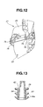
- the projection 75 is shaped generally semi-cylindrical and has a hook portion 75a at a leading end thereof, and as is seen from Fig. 12, U-shaped catcher 76 is projected downward to pivotally engage with the projection 75. Due to provision of hook portion 75a, the pivotal engagement of U-shaped catcher 76 with projection 75 is stably kept.
- each clamp 77 is constructed of a spring metal.
- Each clamp 77 has a lower end that is pivotally connected to a clamp mounting portion 78 formed on air cleaner body 22 and an upper bent portion that is engageable with a boss portion 79 of upper case 25 in a snap action manner. Accordingly, when clamps 77 are disengaged from boss portions 79, air cleaner body 22 is permitted to swing about the hinges (75, 76) between the closed position and the open position. While, when clamps 77 are engaged with boss portions 79, air cleaner body 22 is tightly fitted to the upper case 25 taking its closed position.
- air cleaner element 23 is stably put between air cleaner body 22 and upper case 25 of air cleaner case 21.
- the air cleaner element 23 is put on rectangular flange 71 of air cleaner body 22.
- a sealing ridge 81 is integrally formed on the peripheral portion of rectangular opening 33 of upper case 25.
- sealing ridge 81 is pressed against seal member 28 of air cleaner element 23 to achieve a sealing needed by air cleaner element 23.
- Rectangular flange 71 of air cleaner body 22 is formed around a periphery thereof with a holding ridge 82 for holding seal member 28. It is to be noted that holding ridge 82 is not provided on the ridge where the above-mentioned hinges (75, 76) are provided. Due to provision of holding ridge 82, air cleaner element 23 can be held in position even when air cleaner body 22 is swung down to assume its open position. This facilitates a manual work for changing air cleaner element 23.
- the air intake device of the present invention When, as is seen from Fig. 1, the air intake device of the present invention is properly mounted on internal combustion engine 1, the flat air cleaner case 21 is postured so that the rear end portion thereof extends rearward from the rear end portion of the engine permitting location of air cleaner body 22 behind the rear end of the engine 1. That is, cylinder head cover 4 of the engine 1 and air cleaner body 22 are arranged in tandem.
- a transmission (not shown) is arranged just behind engine 1, which usually brings about a layout wherein due to a reduced size of a front portion of the transmission a certain space is defined just behind cylinder head cover 4. That is, in the present invention, the certain space is effectively used for receiving air cleaner body 22 and thus air cleaner body 22 is permitted to have a sufficient volume or capacity.
- air cleaner element 23 is flatly put between air cleaner body 22 and air cleaner case 21 assuring a satisfied filtering area of air cleaner element 23 while preventing air cleaner case 21 from having a high height.
- a flat but longer construction of air cleaner case 21 brings about a satisfied volume of the same and thus exhibits an effective silencing performance with the aid of the volume of air cleaner body 22.
- air cleaner element 23 can be easily replaced by new one by only opening air cleaner body 22. Furthermore, if desired, air cleaner body 22 can be removed from air cleaner case 21 by only handling hinges (75, 76). In this case, cleaning of the case 21 is easily made.
- air collection space (14) is integrally defined by air cleaner 11 and as is understood from Fig. 2, air collection space (14) and air cleaner element 23 are provided at longitudinally opposed portions of air cleaner 11, respectively.
- the air intake device of the present invention that includes such arrangement, can be made compact in size, particularly in thickness.
Abstract
Description
- The present invention relates in general to air intake devices of internal combustion engines, and more particularly to the air intake devices of a type that includes an air cleaner. More specifically, the present invention is concerned with the air intake devices of a compact type suitable for use in a limited space defined above the engine in an engine room of a motor vehicle.
- Hitherto, various air intake devices have been proposed and put into practical use particularly in the field of wheeled motor vehicles. Some are of a type that includes an air cleaner located away from the internal combustion engine and a flexible duct extending between the air cleaner and an in intake manifold of the engine. However, in recent years, because compactness and aesthetic designing needed by the motor vehicles, the vehicles tend to have a limited engine room space, particularly the space above the engine. In the air intake devices of such vehicles, an air cleaner is directly mounted on the engine to meet the space saving.
- The air intake devices of such space saving type are shown in Laid-open Japanese Patent Applications (Tokkaihei) 10-266913 and 2000-323842.
- However, due to their inherent construction, known air intake devices such as those disclosed by the publications fail to exhibit a satisfied space saving and a satisfied air intake effect.
- Accordingly, it is an object of the present invention to provide an air intake device of an internal combustion engine, that fulfills a satisfied space saving in the engine room while exhibiting a satisfied air intake effect.
- According to a first aspect of the present invention, there is provided an air intake device for use with an internal combustion engine, which comprises an air cleaner case adapted to be mounted on the engine to extend longitudinally along an upper wall of the engine; an opening formed in a longitudinal end portion of a bottom wall of the air cleaner case; an air cleaner body having an open end connected to the opening of the bottom wall of the air cleaner case thereby to communicate an interior of the air cleaner body with that of the air cleaner case; and an air cleaner element put between the air cleaner body and the air cleaner case in a manner to extend across the opening of the bottom wall of the air cleaner case.
- According to a second aspect of the present invention, there is provided an air intake device for use with an internal combustion engine, which comprises an elongate air cleaner case adapted to be mounted on the engine, the air cleaner case having a given end portion that extends beyond one longitudinal end of the engine; an opening formed in the given end portion of the elongate air cleaner case; an air cleaner body having an open end, the air cleaner body being pivotally connected to the given end portion of the air cleaner case, so that the air cleaner body is pivotal between a fitted position wherein the air cleaner body is tightly fitted to the given end portion thereby to connect the open end of the air cleaner body with the opening of the given end portion of the air cleaner case and a released position wherein the air cleaner body is separated from given end portion; a clamp that detachably binds the air cleaner body and the air cleaner case together; a flange formed around the open end of the air cleaner body; and an air cleaner element put on the flange, so that when the air cleaner body assumes the fitted position, the air cleaner element is put between the air cleaner body and the given end portion in a manner to extend to across the opening of the opening of the given end portion.
-
- Fig. 1 is a side view of an internal combustion engine to which an air intake device of the present invention is practically applied;
- Fig. 2 is an exploded view of the air intake device, showing an air cleaner and an upper structure of the engine;
- Fig. 3 is an exploded view of the air cleaner;
- Fig. 4 is a plan view of the air cleaner;
- Fig. 5 is a perspective and inside view of an upper case of the air intake device, to which a throttle body is to be connected;
- Fig. 6 is a perspective view of the upper case;
- Fig. 7 is a plan view of a lower case of the air intake device;
- Fig. 8 is a bottom view of the lower case;
- Fig. 9 is a sectional view taken along the line "IX-IX" of Fig. 8;
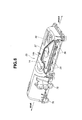
- Fig. 10 is a partially cut side view of an essential portion of the air cleaner, taken from a lateral side of the engine;
- Fig. 11 is a partially cut side view of the essential potion of the air cleaner, taken from a rear side of the engine;
- Fig. 12 is a perspective view of a portion of the air cleaner where a hinge is provided; and
- Fig. 13 is an enlarged sectional view taken along the line "XIII-XIII" of Fig. 7.
-
- Referring to Fig. 1, there is shown an
internal combustion engine 1 to which an air intake device of the present invention is practically applied.Engine 1 shown is of a four cylinder in-line type, used for a FF type (viz., front engine and front drive type) motor vehicle and transversely mounted in an engine room of the vehicle. - As is seen from Fig. 1,
engine 1 comprises generally acylinder block 2 having cylinders, acylinder head 3 mounted oncylinder block 2, acylinder head cover 4 put oncylinder head 3, anoil pan 5 mounted belowcylinder block 2, an intake manifold mounted on a hidden side ofcylinder head 3, anexhaust manifold 6 mounted on this side ofcylinder block 3 and acatalytic converter 7 connected toexhaust manifold 6. - It is to be noted that
engine 1 shown in Fig. 1 is taken from a forward position of an associated motor vehicle. For ease of description, a left part of the engine will be referred to "front part" and a right part of the same will be referred to "rear part". - An
air cleaner 11 is tightly mounted on an upper part ofcylinder head cover 4 through fourbolts 15. As shown,air cleaner 11 has a substantially flat structure and has a portion that extends rearward from the rear end ofengine 1. - As is seen from Fig. 2 that shows a positional relation between
air cleaner 11 andcylinder head cover 4,cylinder head 3 ofengine 1 is equipped with a DOHC type (viz., double over head cam type) valve operating mechanism. For covering the valve operating mechanism,cylinder head cover 4 is mounted oncylinder head 3, that is constructed of a reinforced hard plastic, aluminum, aluminum alloy or the like. - As is seen from Fig. 2,
air cleaner 11 is rectangular in shape, having a width generally the same as that ofcylinder head cover 4.Cylinder head cover 4 is formed at a front end portion thereof with an oil pouring opening 12. As is seen,air cleaner 11 covers entirely the upper part ofcylinder head cover 4 except a part that surrounds oil pouring opening 12. - As is seen from Fig. 2, an
intake manifold 13 is mounted tocylinder head 3 on a side opposite to the side to which the above-mentionedexhaust manifold 6 is mounted. That is, when mounted in a motor vehicle, the side ofcylinder head 3 to which theintake manifold 13 is mounted faces rearward of the associated motor vehicle.Intake manifold 13 is constructed of a reinforced hard plastic and has four air intake branches united together. - An air collection
depressed part 14 is integrally defined byair cleaner 11, which is to be connected to the above-mentionedintake manifold 13. As will be described in detail hereinafter, to air collectiondepressed part 14, there is connected aplastic cover 35. Twobolts 16 are used for connectingair cleaner 11 to intakemanifold 13. - As is well seen from Fig. 3,
air cleaner 11 generally comprises an elongateair cleaner case 21 that is tightly mounted on the upper portion ofengine 1, anair cleaner body 22 that is mounted to a bottom wall ofair cleaner case 21 and anair cleaner element 23 that is put betweenair cleaner case 21 andair cleaner body 22. As is seen,air cleaner body 22 is mounted to a rear end portion of the bottom wall ofair cleaner case 21. -
Air cleaner case 21 comprises alower case 24 and anupper case 25 which are detachably coupled together to constitute a hollow structure.Upper case 25 is longer thanlower case 24 for the purpose which will become apparent as the description proceeds.Lower case 24 is fixed tocylinder head cover 4 through the above-mentionedbolts 15.Upper case 25 is mounted onlower case 24 through fivebolts 26. As seen,air cleaner case 21 is shaped substantially flat. - As is seen from Fig. 3,
air cleaner element 23 is shaped rectangular and comprises apleated filter material 27 that is disposed on arectangular seal member 28.Seal member 28 is made of a flexible urethane foam or the like. It is to be noted that in the illustrated embodiment the interior ofair cleaner body 22 constitutes an upstream side (or dust side) ofair cleaner element 23 and the interior ofair cleaner case 21 constitutes a downstream side (or clean side) of theelement 23. - As shown,
lower case 24 is shorter thanupper case 25. As is seen from Fig. 1,lower case 24 is mounted on the entirely mounted on the given portion ofcylinder head cover 4. Accordingly, when mounted onlower case 24, the rear end portion ofupper case 25 projects rearward (viz., rightward as viewed in Fig. 1) from the rear end oflower case 24, so that the bottom wall of the projected part ofupper case 25 is exposed to the outside facing downward. As shown in Fig. 5, the exposed bottom wall is formed with arectangular opening 33. - As is seen from Figs. 1 and 3, the above-mentioned
air cleaner body 22 is connected to therectangular opening 33 of the exposed bottom wall ofupper case 25. - As is seen from Fig. 5, the bottom wall of
upper case 25 is formed with larger and smallerrectangular openings beam 31. It is to be noted that two inner spaces defined below these twoopenings grid structure 31a defined belowbeam 31. - Upon assembly, larger
rectangular opening 32 is closed bylower case 24 of air cleaner case 21 (see Figs. 1 and 3), and smallerrectangular opening 33 is connected to an upperopen end 22b of air cleaner body 22 (see Fig. 3). - The above-mentioned
lower case 24 and aircleaner body 22 are both constructed of a reinforced hard plastic. - As is seen from Fig. 6, the above-mentioned
upper case 25 is constructed of a reinforced hard plastic. It is to be noted thatupper case 25 shown in the drawing has the cover (35) for air collection depressedpart 14 removed. The cover (35) is also constructed of a reinforced hard plastic and connected to air collection depressedpart 14 through a welding or the like. - Due to provision of the cover (35), air collection depressed
part 14 constitutes an air collection space (14) to which upper open ends of the four air intake branches ofintake manifold 13 are exposed (see Fig. 2). - More specifically, as is seen from Figs. 5 and 6 that show the interior of
upper case 25,air collection space 14 is separated from the main interior space of largerrectangular opening 32 by means of apartition wall 14a. Thispartition wall 14a is formed with acylindrical opening 37 through whichair collection space 14 and the main interior space are communicated. As will be described in detail hereinafter,cylindrical opening 37 is equipped with athrottle device 41 which selectively opens and closes theopening 37. - As is seen from Figs. 4 and 6, along the side edge of
upper case 25, there are integrally provided fourcylindrical portions 36 of which upper open ends are exposed to the interior ofair collection space 14. As is seen from Fig. 2, the fourcylindrical portions 36 are detachably connected to the four air intake branches ofintake manifold 13. - Thus, as is understood from Fig. 3, cleaned air from air
cleaner element 23 is led in order into thesmaller chamber 33 of aircleaner case 21, thelarger chamber 32 of the same through the openings ofgrid structure 31a,air collection space 14 through cylindrical opening 37 (viz., throttle device 41), and into the four air intake branches ofintake manifold 13 through fourcylindrical portions 36. Becauseair collection space 14 has a smaller capacity as compared with thelarger chamber 32, improved transient responsibility is expected by the associated engine. - As is seen from Fig. 11, cover 35 for air collection space (14) has a smoothly curved
upper wall 35a for smoothing the cleaned intake air flowing fromcylindrical opening 37 toward the four air intake branches ofintake manifold 13. - As is understood from Figs. 3 and 5, a
throttle body 41 that formed the above-mentioned throttle device (41) is installed in thelarger chamber 32 of aircleaner case 21.Throttle body 41 has acylindrical air passage 44 in which athrottle valve 43 driven by anelectric motor 42 is operatively installed. As shown, an upper end ofcylindrical air passage 44 is fitted to the above-mentionedcylindrical opening 37. For this fitting, threebolts 46 are used which are engaged with threaded bores (no numerals) formed in aboss portion 45 ofupper case 25 by whichcylindrical opening 37 is defined. For achieving a seal between upper end ofcylindrical air passage 44 andcylindrical opening 37, there is used acircular gasket 49. A lower open end ofcylindrical air passage 44 is exposed to the interior of the largerrectangular chamber 32 of aircleaner case 21. -
Electric motor 42 has a projected connector portion 47 (see Fig. 2) exposed to the upper surface ofupper case 25 through acircular opening 48 that is provided in an upper wall of upper case nearcylindrical opening 37. Although not shown in the drawings, projectedconnector portion 47 has a cylindrical ridge at a root portion thereof. For achieving a seal between the cylindrical ridge andcircular opening 48, there is used acircular gasket 50. - As is seen from Fig. 7,
lower case 24 is equipped along its rectangular peripheral edge with aseal member 51 of flexible rubber material. Due to provision of thisseal member 51, sealing betweenlower case 24 andupper case 25 is achieved. More specifically, the rectangular peripheral edge oflower case 24 is formed with agroove 52 for detachably receivingseal member 51. As is seen from Figs. 5 and 10,upper case 25 is formed along its rectangular peripheral edge with aridge 53. That is, upon coupling of these lower andupper cases ridge 53 is pressed againstseal member 51 to achieve the sealing. It is to be noted that in Fig. 3, theseal member 51 is not shown. - As has been mentioned hereinabove,
lower case 24 of aircleaner case 21 is fixed tocylinder head cover 4 through four bolts 15 (see Fig. 2). As is seen from Figs. 2, 7, 8 and 9, twobolt hole portions 55 forbolts 15 that are provided at the front part oflower case 24 and the other twobolt hole portions 56 forbolts 15 that are provided at the rear part oflower case 24 are sized and constructed by considering the shape of the upper surface ofcylinder head cover 4. That is, thebolt hole portions 56 have each a leg portion. - As is understood from Figs. 8 and 9,
lower case 24 of aircleaner case 21 has a plurality ofdepressions 59 for avoiding interference with coil members (not shown) mounted on the upper surface ofcylinder head cover 4. Each coil member is connected to an ignition plug projected into a corresponding cylinder of the engine. As is seen from Fig. 8, the bottom surface oflower case 24 is equipped with two sound insulatingmembers member lower case 24 and that of the upper shape ofcylinder head cover 4. Eachsound insulating member lower case 24, and upon mounting oflower case 24 ontocylinder head cover 4, the insulatingmember sound insulating members cylinder head cover 4 is damped. - As is seen from Figs. 7 and 8, the bottom wall of
lower case 24 is integrally formed with a blow-by gas pipe 61. As is seen from Fig. 13, blow-by gas pipe 61 comprises an inner portion that is projected into the interior of thelarger chamber 32 of aircleaner case 21 and an outer portion that is projected toward thecylinder head cover 4. The inner portion is formed with a blow-bygas introducing opening 62 that is exposed to the interior of thelarger chamber 32 of aircleaner case 21. - As is seen from Fig. 2, when
lower case 24 is properly mounted oncylinder head cover 4, the outer portion of blow-by gas pipe 61 is projected into a blow-bygas opening 63 formed in the upper wall ofcylinder head cover 4. That is, blow-by gas incylinder head cover 4 is led into the interior of thelarger chamber 32 of aircleaner case 21 fromgas opening 63 through blow-by gas pipe 61. As is seen from Fig. 13, for achieving sealing betweengas opening 63 andgas pipe 61, acylindrical seal member 64 with a plurality ofseal lips 64a is disposed on the outer portion of blow-by gas pipe 61.Seal member 64 is constructed of a flexible rubber material, flexible plastic material or the like. - In the following, construction of air
cleaner body 22 will be described in detail with reference to the drawings. - As has been described hereinabove, air cleaner body 22 (see Figs. 3 and 5) is connected to the rectangular
lower opening 33 ofupper case 25 in a manner to cover the same. As is seen from Fig. 3, aircleaner body 22 has a smoothly coveredhollow body portion 22a, arectangular flange 71 integrally formed on one end ofhollow body portion 22a and a cylindricalair inlet portion 72 integrally formed on one side wall ofhollow body portion 22a. Upon mounting of the air intake device on an associated motor vehicle,air inlet portion 72 is directed forward of the vehicle. Although not shown in the drawings, an air intake duct is connected toair inlet portion 72. The air intake duct runs and extends in a limited space of the engine room and has an air inlet mouth facing forward of the vehicle. - As is seen from Figs. 3 and 11, a
back wall 73 of aircleaner body 22 that facesair inlet portion 72 is curved smoothly to smoothly guide intake air toward aircleaner element 23 that is tightly mounted onrectangular flange 71. - As is seen from Figs. 11 and 12, a pair of hinges (75, 76) are provided between
rectangular flange 71 of aircleaner body 22 andupper case 25 of aircleaner case 21. Thus, aircleaner body 22 can swing relative toupper case 25. That is, for changing aircleaner element 23, aircleaner body 22 is swung to expose or open theelement 23. As is well shown in Fig. 12, each hinge comprises aprojection 75 that is formed onrectangular flange 71 of aircleaner body 22 and aU-shaped catcher 76 that is formed on a peripheral portion (see Fig. 5) ofrectangular opening 33 ofupper case 25 of aircleaner case 21 and pivotally engaged withprojection 75. - More specifically, as is seen from Figs. 11 and 12, the
projection 75 is shaped generally semi-cylindrical and has ahook portion 75a at a leading end thereof, and as is seen from Fig. 12,U-shaped catcher 76 is projected downward to pivotally engage with theprojection 75. Due to provision ofhook portion 75a, the pivotal engagement ofU-shaped catcher 76 withprojection 75 is stably kept. - It is now to be noted that even when air
cleaner body 22 is swung down to expose aircleaner element 23, thebody 22 is kept held by the hinges. However, when, for the purpose of taking thebody 22 off the hinges, thebody 22 is slightly lifted to disengageprojections 75 fromU-shaped catchers 76, thebody 22 can be removed fromupper case 25 of aircleaner case 21. - As is seen from Fig. 3, for holding air
cleaner body 22 in its closed position relative toupper case 25, twoclamps 77 are provided on thebody 22. As is seen from Figs. 10 and 11, eachclamp 77 is constructed of a spring metal. Eachclamp 77 has a lower end that is pivotally connected to aclamp mounting portion 78 formed on aircleaner body 22 and an upper bent portion that is engageable with aboss portion 79 ofupper case 25 in a snap action manner. Accordingly, when clamps 77 are disengaged fromboss portions 79, aircleaner body 22 is permitted to swing about the hinges (75, 76) between the closed position and the open position. While, when clamps 77 are engaged withboss portions 79, aircleaner body 22 is tightly fitted to theupper case 25 taking its closed position. Of course, as has been mentioned hereinabove, aircleaner element 23 is stably put between aircleaner body 22 andupper case 25 of aircleaner case 21. - That is, as is seen from Fig. 10, the
air cleaner element 23 is put onrectangular flange 71 of aircleaner body 22. As shown, a sealingridge 81 is integrally formed on the peripheral portion ofrectangular opening 33 ofupper case 25. Thus, upon closing of aircleaner body 22 relative toupper case 25, sealingridge 81 is pressed againstseal member 28 of aircleaner element 23 to achieve a sealing needed by aircleaner element 23.Rectangular flange 71 of aircleaner body 22 is formed around a periphery thereof with a holdingridge 82 for holdingseal member 28. It is to be noted that holdingridge 82 is not provided on the ridge where the above-mentioned hinges (75, 76) are provided. Due to provision of holdingridge 82, aircleaner element 23 can be held in position even when aircleaner body 22 is swung down to assume its open position. This facilitates a manual work for changing aircleaner element 23. - When, as is seen from Fig. 1, the air intake device of the present invention is properly mounted on
internal combustion engine 1, the flatair cleaner case 21 is postured so that the rear end portion thereof extends rearward from the rear end portion of the engine permitting location of aircleaner body 22 behind the rear end of theengine 1. That is,cylinder head cover 4 of theengine 1 and aircleaner body 22 are arranged in tandem. It is to be noted that in an engine room of motor vehicles, a transmission (not shown) is arranged just behindengine 1, which usually brings about a layout wherein due to a reduced size of a front portion of the transmission a certain space is defined just behindcylinder head cover 4. That is, in the present invention, the certain space is effectively used for receiving aircleaner body 22 and thus aircleaner body 22 is permitted to have a sufficient volume or capacity. - As is seen from Fig. 1, air
cleaner element 23 is flatly put between aircleaner body 22 and aircleaner case 21 assuring a satisfied filtering area of aircleaner element 23 while preventing aircleaner case 21 from having a high height. A flat but longer construction of aircleaner case 21 brings about a satisfied volume of the same and thus exhibits an effective silencing performance with the aid of the volume of aircleaner body 22. - As has been described hereinabove, air
cleaner element 23 can be easily replaced by new one by only opening aircleaner body 22. Furthermore, if desired, aircleaner body 22 can be removed from aircleaner case 21 by only handling hinges (75, 76). In this case, cleaning of thecase 21 is easily made. - In the air intake device of the present invention, an arrangement is employed wherein air collection space (14) is integrally defined by
air cleaner 11 and as is understood from Fig. 2, air collection space (14) and aircleaner element 23 are provided at longitudinally opposed portions ofair cleaner 11, respectively. Thus, the air intake device of the present invention, that includes such arrangement, can be made compact in size, particularly in thickness. - The entire contents of Japanese Patent Application 2002-39655 (filed February 18, 2002) are incorporated herein by reference.
- Although the invention has been described above with reference to the embodiment of the invention, the invention is not limited to such embodiment as described above. Various modifications and variations of such embodiment may be carried out by those skilled in the art, in light of the above description.
Claims (24)
- An air intake device for use with an internal combustion engine (1), comprising:an air cleaner case (21) adapted to be mounted on the engine to extend longitudinally along an upper wall of the engine;an opening (33) formed in a longitudinal end portion of a bottom wall of the air cleaner case (21);an air cleaner body (22) having an open end (22b) connected to the opening (33) of the bottom wall of the air cleaner case (21) thereby to communicate an interior of the air cleaner body (22) with that of the air cleaner case (21); andan air cleaner element (23) put between the air cleaner body (22) and the air cleaner case (21) in a manner to extend across the opening (33) of the bottom wall of the air cleaner case (21).
- An air intake device as claimed in Claim 1, in which the longitudinal end portion of the bottom wall of the air cleaner case (21) extends beyond one longitudinal end of the engine (1) thereby to define a certain space below the longitudinal end portion, the certain space accommodating the air cleaner body (22).
- An air intake device as claimed in Claim 1, in which the interior of the air cleaner body (22) is communicated with the open air through an opening (72) formed in the air cleaner body (22) and the interior of the air cleaner case (21) is communicated with an intake part of the engine (1), so that the interior of the air cleaner body (22) and that of the air cleaner case (21) constitute dust and clean sides of the air cleaner element (23) respectively.
- An air intake device as claimed in Claim 3, in which the interior of the air cleaner case (21) has an air outlet portion (36) to which an air collection part of an intake manifold (13) is connected.
- An air intake device as claimed in Claim 3, in which the air cleaner case (21) comprises:a lower case (24) adapted to be fixed to the upper wall of the engine (1); andan upper case (25) mounted on the lower case (24) in a manner to allow the air cleaner case (21) to have a hollow structure.
- An air intake device as claimed in Claim 4, further comprising a throttle body (41) that has an air passage (44) in which a throttle valve (43) is pivotally installed to selectively open and close the air passage (44), the throttle body (41) being housed in the interior of the air cleaner case (21) having the air passage (44) connected to the air outlet portion (37) of the air cleaner case (21).
- An air intake device as claimed in Claim 1, in which the air cleaner body (22) is pivotally connected to the bottom wall of the air cleaner case (21) by means of a hinge mechanism (75, 76).
- An air intake device as claimed in Claim 7, in which the open end (22b) of the air cleaner body (22) is formed around a peripheral portion thereof with a holding ridge (71) to hold the air cleaner element (23).
- An air intake device as claimed in Claim 7, in which the hinge mechanism (75, 76) comprises:a projection (75) formed on the air cleaner body (22); anda U-shaped catcher (76) formed on the air cleaner case (21), the U-shaped catcher (76) being pivotally engaged with the projection (75).
- An air intake device as claimed in Claim 9, in which the projection (75) and the U-shaped catcher (76) are detachably engaged.
- An air intake device as claimed in Claim 1, further comprising a sound insulating member (57, 58) that is put between the upper wall of the engine (1) and the air cleaner case (21).
- An air intake device as claimed in Claim 1, in which the air cleaner case (21) comprises:a lower case (24) adapted to be fixed to the upper wall of the engine (1);an upper case (25) longer than the lower case (24), the upper case (25) being mounted on the lower case (24) in such a manner that a given end portion of the upper case (25) projects longitudinally outward beyond an end of the lower case (24), the given end portion having the opening (33) to which the open end (22b) of the air cleaner body (22) is connected.
- An air intake device as claimed in Claim 12, in which the upper case (25) comprises:a first chamber (33) defined by the given end portion of the upper case (25);a second chamber (32) defined by a major portion of the upper case (25); anda third chamber (14) defined by the major portion of the upper case (25), the third and second chambers (14, 32) being separated by a partition wall (14a) arranged therebetween, the third chamber (14) is placed on the second chamber (32);an air outlet portion (36) merged with an interior of the third chamber (14), the air outlet portion (36) being adapted to connect to an intake part (13) of the engine (1); andan opening (37) formed in the partition wall (14a) to provide a fluid communication between the second and third chambers (14, 32).
- An air intake device as claimed in Claim 13, further comprises a throttle body (41) that is installed in the second chamber (32) having its air passage (44) connected to the opening (37) of the partition wall (14a).
- An air intake device as claimed in Claim 14, in which the throttle body (41) comprises:a passage (44) having one end connected to the opening (37) of the partition wall (14a) and the other end exposed to the interior of the second chamber (32);a throttle valve (43) pivotally installed in the passage (44) to open and close the same; andan electric motor (42) that drives the throttle valve (43).
- An air intake device as claimed in Claim 13, in which the first and second chambers (33, 32) are separated by a grid structure (31a) that has openings through which the first and second chambers (33, 32) are fluidly communicated.
- An air intake device as claimed in Claim 13, in which the third chamber (14) comprises:a depressed portion (14) formed on the upper case (25); anda cover (35) welded to the upper case (25) to cover the depressed portion (14).
- An air intake device as claimed in Claim 13, in which the air cleaner body (22) is pivotally connected to the given end portion of the upper case (25) by means of a hinge mechanism (75, 76).
- An air intake device as claimed in Claim 18, in which the hinge mechanism (75, 76) comprises:a projection (75) formed on the air cleaner body (22); anda U-shaped catcher (76) formed on the air cleaner case (21) and pivotally and detachably engaged with the projection (75).
- An air intake device as claimed in Claim 19, further comprising a clamp (77) of spring metal for binding the air cleaner body (22) to the air cleaner case (21), the clamp (77) having one end that is pivotally connected to the air cleaner body (22) and the other end that is engageable with a boss portion (79) of the upper case (25) of the air cleaner case (21) in a snap action manner.
- An air intake device as claimed in Claim 20, in which the air cleaner body (22) is formed around the opening thereof with a flange (71) for putting thereon the air cleaner element (23).
- An air intake device as claimed in Claim 21, in which the air cleaner element (23) comprises:a seal member (28) adapted to be disposed on the flange (71) of the air cleaner body (22); anda pleated filter material (27) mounted on the seal member (28).
- An air intake device as claimed in Claim 22, in which the given end portion of the upper case (25) of the air cleaner case (21) is formed with a sealing ridge (81) that is pressed against the seal member (28) of the air cleaner element (23) to achieve sealing therebetween when the air cleaner body (22) is tightly fitted to the given end portion of the upper case (25).
- An air intake device for use with an internal combustion engine, comprising:an elongate air cleaner case (21) adapted to be mounted on the engine (1), the air cleaner case (21) having a given end portion that extends beyond one longitudinal end of the engine (1);an opening (33) formed in the given end portion of the elongate air cleaner case (21);an air cleaner body (22) having an open end (22b), the air cleaner body (22) being pivotally connected to the given end portion of the air cleaner case (21), so that the air cleaner body (22) is pivotal between a fitted position wherein the air cleaner body (22) is tightly fitted to the given end portion thereby to connect the open end (22b) of the air cleaner body (22) with the opening (33) of the given end portion of the air cleaner case (21) and a released position wherein the air cleaner body (22) is separated from given end portion;a clamp (77) that detachably binds the air cleaner body (22) and the air cleaner case (21) together;a flange (71) formed around the open end (22b) of the air cleaner body (22); andan air cleaner element (23) put on the flange (71), so that when the air cleaner body (22) assumes the fitted position, the air cleaner element (23) is put between the air cleaner body (22) and the given end portion in a manner to extend to across the opening of the given end portion.
Applications Claiming Priority (2)
| Application Number | Priority Date | Filing Date | Title |
|---|---|---|---|
| JP2002039655A JP3864100B2 (en) | 2002-02-18 | 2002-02-18 | Intake device for internal combustion engine |
| JP2002039655 | 2002-02-18 |
Publications (2)
| Publication Number | Publication Date |
|---|---|
| EP1338786A1 true EP1338786A1 (en) | 2003-08-27 |
| EP1338786B1 EP1338786B1 (en) | 2005-04-13 |
Family
ID=27655153
Family Applications (1)
| Application Number | Title | Priority Date | Filing Date |
|---|---|---|---|
| EP03003597A Expired - Lifetime EP1338786B1 (en) | 2002-02-18 | 2003-02-17 | Air intake device of internal combustion enginge |
Country Status (4)
| Country | Link |
|---|---|
| US (1) | US6863044B2 (en) |
| EP (1) | EP1338786B1 (en) |
| JP (1) | JP3864100B2 (en) |
| DE (1) | DE60300487T2 (en) |
Cited By (7)
| Publication number | Priority date | Publication date | Assignee | Title |
|---|---|---|---|---|
| WO2005026522A1 (en) * | 2003-09-08 | 2005-03-24 | K & N Engineering, Inc. | Air box lid having an integrated filter |
| EP1752650A1 (en) * | 2004-06-01 | 2007-02-14 | Daihatsu Motor Co., Ltd. | Air intake device of internal combustion engine |
| FR2895460A1 (en) * | 2005-12-22 | 2007-06-29 | Renault Sas | Power train`s distribution and/or accessory element e.g. main pulley, safety hood for motor vehicle, has assembly comprising main pulley which engages secondary pulley connected to axle of alternator by belt |
| FR2931516A1 (en) * | 2008-05-20 | 2009-11-27 | Peugeot Citroen Automobiles Sa | Air filter for internal combustion engine of motor vehicle, has filtering element including filtration cartridge arranged on face of support, where filtration cartridge is located in interior volume defined by support and flap |
| EP2679796A3 (en) * | 2011-10-27 | 2014-04-30 | C.R.F. Società Consortile per Azioni | Intake assembly for an internal combustion engine |
| CN105317598A (en) * | 2014-07-29 | 2016-02-10 | 现代自动车株式会社 | Insert type expansion pipe-integrated air cleaner and engine intake system thereof |
| US10760669B2 (en) | 2012-03-22 | 2020-09-01 | Elringklinger Ag | Machine or vehicle component |
Families Citing this family (24)
| Publication number | Priority date | Publication date | Assignee | Title |
|---|---|---|---|---|
| AU2001272678A1 (en) * | 2000-07-28 | 2002-02-13 | Visteon Global Technologies, Inc. | An air intake arrangement for an internal combustion engine |
| US6726871B2 (en) * | 2001-06-07 | 2004-04-27 | Siemens Vdo Automotive, Inc. | Method and apparatus for attachment of air cleaner housing |
| JP2005076602A (en) * | 2003-09-03 | 2005-03-24 | Honda Motor Co Ltd | Throttle body protecting device |
| JPWO2005035968A1 (en) * | 2003-10-08 | 2006-12-21 | 株式会社ミクニ | Intake device |
| KR100599297B1 (en) * | 2004-07-02 | 2006-07-14 | 현대자동차주식회사 | air intake system for a V-type engine |
| JP4539470B2 (en) * | 2005-07-12 | 2010-09-08 | スズキ株式会社 | Engine intake system |
| US7887624B2 (en) | 2005-10-11 | 2011-02-15 | Black & Decker Inc. | Gas concrete saw filtration system |
| JP4858710B2 (en) * | 2007-05-14 | 2012-01-18 | スズキ株式会社 | Engine intake system |
| GB2450717A (en) * | 2007-07-04 | 2009-01-07 | Black & Decker Inc | Power cutter including air filter cleaning mechanism |
| GB2450720A (en) * | 2007-07-04 | 2009-01-07 | Black & Decker Inc | Power cutter with pleated filter |
| US8272134B2 (en) * | 2007-07-04 | 2012-09-25 | Black & Decker Inc. | Power cutter |
| JP5222006B2 (en) * | 2008-04-10 | 2013-06-26 | 株式会社マーレ フィルターシステムズ | Intake duct for internal combustion engine |
| DE202008005019U1 (en) * | 2008-04-10 | 2009-08-20 | Mann+Hummel Gmbh | Cylinder head cover for a cylinder head of an internal combustion engine |
| KR101178227B1 (en) | 2010-09-28 | 2012-08-30 | 기아자동차주식회사 | Intergrated air intake system |
| DE102011076001A1 (en) * | 2011-05-17 | 2012-11-22 | Elringklinger Ag | Bonnet for mounting in cylinder head-sided portion of diesel engine block, has flaps mounted at bonnet to control flow of charging air through charging air supply channels of charging air distribution unit |
| DE102011081484A1 (en) | 2011-08-24 | 2013-02-28 | Mahle International Gmbh | bearing block |
| JP5949074B2 (en) * | 2012-04-05 | 2016-07-06 | スズキ株式会社 | Intake system of internal combustion engine |
| DE102012104334A1 (en) * | 2012-05-21 | 2013-11-21 | Dr. Ing. H.C. F. Porsche Aktiengesellschaft | cladding element |
| JP5974836B2 (en) * | 2012-11-05 | 2016-08-23 | トヨタ紡織株式会社 | Housing for vehicle parts |
| JP6319032B2 (en) * | 2014-10-08 | 2018-05-09 | トヨタ紡織株式会社 | Air cleaner |
| KR102361498B1 (en) * | 2017-09-05 | 2022-02-10 | 현대자동차주식회사 | Air cleaner assembly for vehicle |
| US10125729B1 (en) * | 2017-09-07 | 2018-11-13 | Indmar Products Company Inc. | Throttle body adapter for marine engine air intake |
| JP7083746B2 (en) * | 2018-12-26 | 2022-06-13 | 愛三工業株式会社 | Intake device |
| US11193441B1 (en) * | 2021-05-15 | 2021-12-07 | Gale C. Banks, III | Intake adaption system |
Citations (6)
| Publication number | Priority date | Publication date | Assignee | Title |
|---|---|---|---|---|
| DE3232583A1 (en) * | 1982-09-02 | 1984-03-08 | Daimler-Benz Ag, 7000 Stuttgart | Device for cleaning the intake air of an internal combustion engine |
| DE19507354A1 (en) * | 1995-03-03 | 1996-09-05 | Vdo Schindling | Air induction module for four-stroke combustion engine |
| JPH10266913A (en) * | 1997-03-25 | 1998-10-06 | Daihatsu Motor Co Ltd | Air cleaner |
| EP0931926A1 (en) * | 1998-01-23 | 1999-07-28 | Renault | Internal combustion engine with compact intake system |
| US5950586A (en) * | 1996-06-29 | 1999-09-14 | Robert Bosch Gmbh | Air conduction system for a vehicle |
| US6263850B1 (en) * | 1999-08-03 | 2001-07-24 | Visteon Global Technologies, Inc. | Integrated air induction module for gasoline engines |
Family Cites Families (17)
| Publication number | Priority date | Publication date | Assignee | Title |
|---|---|---|---|---|
| JPS59103954A (en) * | 1982-12-06 | 1984-06-15 | Honda Motor Co Ltd | Suction device of internal-combustion engine |
| SE513061C2 (en) * | 1992-06-30 | 2000-06-26 | Fanja Ltd | Method and apparatus for changing the compression ratio in an internal combustion engine |
| SE470567B (en) * | 1993-01-21 | 1994-08-29 | Electrolux Ab | Device for cutting machine, circular saw machine or equivalent |
| JPH07103092A (en) | 1993-10-01 | 1995-04-18 | Toyota Motor Corp | Structure of engine |
| JPH0976973A (en) * | 1995-09-11 | 1997-03-25 | Yamaha Motor Co Ltd | Air intake device of motorcycle |
| JPH10184468A (en) | 1996-12-27 | 1998-07-14 | Suzuki Motor Corp | Intake system drainage structure of engine |
| JPH10246160A (en) | 1997-02-28 | 1998-09-14 | Suzuki Motor Corp | Air cleaner device for internal combustion engine |
| JPH10246159A (en) | 1997-02-28 | 1998-09-14 | Suzuki Motor Corp | Intake structure for internal combustion engine |
| JP3442627B2 (en) | 1997-10-21 | 2003-09-02 | ダイハツ工業株式会社 | Air cleaner duct support structure |
| JP3669470B2 (en) | 1998-04-10 | 2005-07-06 | 本田技研工業株式会社 | Air cleaner |
| US6022391A (en) * | 1999-01-29 | 2000-02-08 | United Air Filter, Inc. | Filter assembly for cleaning cooling air for engines |
| US6162269A (en) * | 1999-01-29 | 2000-12-19 | United Air Filter, Inc. | Filter assembly for cleaning cooling air for engines |
| JP4253824B2 (en) | 1999-02-04 | 2009-04-15 | マツダ株式会社 | Engine intake system |
| US6357414B1 (en) * | 1999-04-22 | 2002-03-19 | Visteon Global Technologies, Inc. | Air manifold mounting for engine control circuitry |
| DE29922748U1 (en) * | 1999-12-24 | 2000-03-09 | Stihl Maschf Andreas | Arrangement of an air filter and a membrane carburetor |
| JP3811590B2 (en) * | 2000-03-30 | 2006-08-23 | 本田技研工業株式会社 | Air cleaner device for vehicles |
| JP2001323842A (en) | 2000-05-16 | 2001-11-22 | Auto Network Gijutsu Kenkyusho:Kk | Harness structure for engine relating part |
-
2002
- 2002-02-18 JP JP2002039655A patent/JP3864100B2/en not_active Expired - Lifetime
-
2003
- 2003-02-14 US US10/366,517 patent/US6863044B2/en not_active Expired - Lifetime
- 2003-02-17 DE DE60300487T patent/DE60300487T2/en not_active Expired - Lifetime
- 2003-02-17 EP EP03003597A patent/EP1338786B1/en not_active Expired - Lifetime
Patent Citations (6)
| Publication number | Priority date | Publication date | Assignee | Title |
|---|---|---|---|---|
| DE3232583A1 (en) * | 1982-09-02 | 1984-03-08 | Daimler-Benz Ag, 7000 Stuttgart | Device for cleaning the intake air of an internal combustion engine |
| DE19507354A1 (en) * | 1995-03-03 | 1996-09-05 | Vdo Schindling | Air induction module for four-stroke combustion engine |
| US5950586A (en) * | 1996-06-29 | 1999-09-14 | Robert Bosch Gmbh | Air conduction system for a vehicle |
| JPH10266913A (en) * | 1997-03-25 | 1998-10-06 | Daihatsu Motor Co Ltd | Air cleaner |
| EP0931926A1 (en) * | 1998-01-23 | 1999-07-28 | Renault | Internal combustion engine with compact intake system |
| US6263850B1 (en) * | 1999-08-03 | 2001-07-24 | Visteon Global Technologies, Inc. | Integrated air induction module for gasoline engines |
Non-Patent Citations (1)
| Title |
|---|
| PATENT ABSTRACTS OF JAPAN vol. 1999, no. 01 29 January 1999 (1999-01-29) * |
Cited By (11)
| Publication number | Priority date | Publication date | Assignee | Title |
|---|---|---|---|---|
| WO2005026522A1 (en) * | 2003-09-08 | 2005-03-24 | K & N Engineering, Inc. | Air box lid having an integrated filter |
| EP1752650A1 (en) * | 2004-06-01 | 2007-02-14 | Daihatsu Motor Co., Ltd. | Air intake device of internal combustion engine |
| EP1752650A4 (en) * | 2004-06-01 | 2010-09-01 | Daihatsu Motor Co Ltd | Air intake device of internal combustion engine |
| FR2895460A1 (en) * | 2005-12-22 | 2007-06-29 | Renault Sas | Power train`s distribution and/or accessory element e.g. main pulley, safety hood for motor vehicle, has assembly comprising main pulley which engages secondary pulley connected to axle of alternator by belt |
| WO2007074293A2 (en) * | 2005-12-22 | 2007-07-05 | Renault S.A.S | Protective crankcase for a drive train |
| WO2007074293A3 (en) * | 2005-12-22 | 2007-08-16 | Renault Sa | Protective crankcase for a drive train |
| FR2931516A1 (en) * | 2008-05-20 | 2009-11-27 | Peugeot Citroen Automobiles Sa | Air filter for internal combustion engine of motor vehicle, has filtering element including filtration cartridge arranged on face of support, where filtration cartridge is located in interior volume defined by support and flap |
| EP2679796A3 (en) * | 2011-10-27 | 2014-04-30 | C.R.F. Società Consortile per Azioni | Intake assembly for an internal combustion engine |
| US10760669B2 (en) | 2012-03-22 | 2020-09-01 | Elringklinger Ag | Machine or vehicle component |
| CN105317598A (en) * | 2014-07-29 | 2016-02-10 | 现代自动车株式会社 | Insert type expansion pipe-integrated air cleaner and engine intake system thereof |
| CN105317598B (en) * | 2014-07-29 | 2019-07-23 | 现代自动车株式会社 | The air cleaner and its engine aspirating system of integrated insert type expansion tube |
Also Published As
| Publication number | Publication date |
|---|---|
| US20030154951A1 (en) | 2003-08-21 |
| JP3864100B2 (en) | 2006-12-27 |
| DE60300487T2 (en) | 2005-09-01 |
| DE60300487D1 (en) | 2005-05-19 |
| US6863044B2 (en) | 2005-03-08 |
| EP1338786B1 (en) | 2005-04-13 |
| JP2003239815A (en) | 2003-08-27 |
Similar Documents
| Publication | Publication Date | Title |
|---|---|---|
| EP1338786B1 (en) | Air intake device of internal combustion enginge | |
| JP3280209B2 (en) | Muffler structure of internal combustion engine | |
| JP4254349B2 (en) | Intake device for internal combustion engine | |
| WO1998022705A1 (en) | Intake device of internal combustion engine | |
| MXPA05000739A (en) | Panel type air filter element with integral baffle. | |
| JP3974333B2 (en) | Air cleaner structure for vehicles | |
| CA2467608C (en) | Manually operated tool | |
| JP3727249B2 (en) | Air filter casing with baffle cylinder | |
| JP4305828B2 (en) | Intake manifold for internal combustion engine | |
| US7114475B2 (en) | Air cleaner, valve cover and intake manifold assembly | |
| JP4415257B2 (en) | Engine intake structure | |
| EP1433947B1 (en) | Internal combustion engine air filtering device | |
| JP4316331B2 (en) | V-type engine intake system for motorcycles | |
| JP4334952B2 (en) | Engine intake device and motorcycle V-type engine equipped with the intake device | |
| JP4243832B2 (en) | Engine intake structure | |
| WO1998049440A1 (en) | Integrated duct and resonator for an automobile engine air induction system | |
| JP4235946B2 (en) | Engine intake structure | |
| JP3974342B2 (en) | Motorcycle air cleaner equipment | |
| JP3933767B2 (en) | Intake device for internal combustion engine | |
| JP2009013942A (en) | Breather device of engine | |
| JP3668446B2 (en) | Intake device for multi-cylinder internal combustion engine | |
| JP2004138045A (en) | Intake system of engine | |
| JP2005120915A (en) | Air cleaner of internal combustion engine | |
| JP2511365Y2 (en) | Work vehicle engine intake system | |
| JP2000145427A (en) | Blow-by gas routing mechanism for internal combustion engines |
Legal Events
| Date | Code | Title | Description |
|---|---|---|---|
| PUAI | Public reference made under article 153(3) epc to a published international application that has entered the european phase |
Free format text: ORIGINAL CODE: 0009012 |
|
| 17P | Request for examination filed |
Effective date: 20030217 |
|
| AK | Designated contracting states |
Designated state(s): AT BE BG CH CY CZ DE DK EE ES FI FR GB GR HU IE IT LI LU MC NL PT SE SI SK TR |
|
| AX | Request for extension of the european patent |
Extension state: AL LT LV MK RO |
|
| 17Q | First examination report despatched |
Effective date: 20040225 |
|
| AKX | Designation fees paid |
Designated state(s): DE FR GB |
|
| GRAP | Despatch of communication of intention to grant a patent |
Free format text: ORIGINAL CODE: EPIDOSNIGR1 |
|
| RIN1 | Information on inventor provided before grant (corrected) |
Inventor name: YAMASHITA, KOUJI Inventor name: MIYAMOTO, HIDEAKI Inventor name: KITABAYASHI, SHINSUKE Inventor name: NAKAMURA, AKIO |
|
| GRAS | Grant fee paid |
Free format text: ORIGINAL CODE: EPIDOSNIGR3 |
|
| GRAA | (expected) grant |
Free format text: ORIGINAL CODE: 0009210 |
|
| AK | Designated contracting states |
Kind code of ref document: B1 Designated state(s): DE FR GB |
|
| REG | Reference to a national code |
Ref country code: GB Ref legal event code: FG4D |
|
| REF | Corresponds to: |
Ref document number: 60300487 Country of ref document: DE Date of ref document: 20050519 Kind code of ref document: P |
|
| ET | Fr: translation filed | ||
| PLBE | No opposition filed within time limit |
Free format text: ORIGINAL CODE: 0009261 |
|
| STAA | Information on the status of an ep patent application or granted ep patent |
Free format text: STATUS: NO OPPOSITION FILED WITHIN TIME LIMIT |
|
| 26N | No opposition filed |
Effective date: 20060116 |
|
| REG | Reference to a national code |
Ref country code: FR Ref legal event code: CD |
|
| REG | Reference to a national code |
Ref country code: FR Ref legal event code: PLFP Year of fee payment: 14 |
|
| REG | Reference to a national code |
Ref country code: FR Ref legal event code: PLFP Year of fee payment: 15 |
|
| REG | Reference to a national code |
Ref country code: FR Ref legal event code: PLFP Year of fee payment: 16 |
|
| PGFP | Annual fee paid to national office [announced via postgrant information from national office to epo] |
Ref country code: FR Payment date: 20211216 Year of fee payment: 20 Ref country code: GB Payment date: 20211230 Year of fee payment: 20 |
|
| PGFP | Annual fee paid to national office [announced via postgrant information from national office to epo] |
Ref country code: DE Payment date: 20211222 Year of fee payment: 20 |
|
| REG | Reference to a national code |
Ref country code: DE Ref legal event code: R081 Ref document number: 60300487 Country of ref document: DE Owner name: NISSAN MOTOR CO., LTD., YOKOHAMA-SHI, JP Free format text: FORMER OWNERS: NISSAN MOTOR CO., LTD., YOKOHAMA-SHI, KANAGAWA-KEN, JP; MAHLE FILTER SYSTEMS JAPAN CORP., TOKIO, JP Ref country code: DE Ref legal event code: R081 Ref document number: 60300487 Country of ref document: DE Owner name: MAHLE JAPAN LTD., JP Free format text: FORMER OWNERS: NISSAN MOTOR CO., LTD., YOKOHAMA-SHI, KANAGAWA-KEN, JP; MAHLE FILTER SYSTEMS JAPAN CORP., TOKIO, JP |
|
| REG | Reference to a national code |
Ref country code: DE Ref legal event code: R071 Ref document number: 60300487 Country of ref document: DE |
|
| REG | Reference to a national code |
Ref country code: GB Ref legal event code: PE20 Expiry date: 20230216 |
|
| PG25 | Lapsed in a contracting state [announced via postgrant information from national office to epo] |
Ref country code: GB Free format text: LAPSE BECAUSE OF EXPIRATION OF PROTECTION Effective date: 20230216 |