EP1338471A2 - Switch assembly mounted in a steering wheel - Google Patents
Switch assembly mounted in a steering wheel Download PDFInfo
- Publication number
- EP1338471A2 EP1338471A2 EP03002076A EP03002076A EP1338471A2 EP 1338471 A2 EP1338471 A2 EP 1338471A2 EP 03002076 A EP03002076 A EP 03002076A EP 03002076 A EP03002076 A EP 03002076A EP 1338471 A2 EP1338471 A2 EP 1338471A2
- Authority
- EP
- European Patent Office
- Prior art keywords
- switch
- airbag
- steering wheel
- assembly
- base
- Prior art date
- Legal status (The legal status is an assumption and is not a legal conclusion. Google has not performed a legal analysis and makes no representation as to the accuracy of the status listed.)
- Withdrawn
Links
Images





Classifications
-
- H—ELECTRICITY
- H01—ELECTRIC ELEMENTS
- H01H—ELECTRIC SWITCHES; RELAYS; SELECTORS; EMERGENCY PROTECTIVE DEVICES
- H01H13/00—Switches having rectilinearly-movable operating part or parts adapted for pushing or pulling in one direction only, e.g. push-button switch
- H01H13/02—Details
-
- B—PERFORMING OPERATIONS; TRANSPORTING
- B60—VEHICLES IN GENERAL
- B60R—VEHICLES, VEHICLE FITTINGS, OR VEHICLE PARTS, NOT OTHERWISE PROVIDED FOR
- B60R21/00—Arrangements or fittings on vehicles for protecting or preventing injuries to occupants or pedestrians in case of accidents or other traffic risks
- B60R21/02—Occupant safety arrangements or fittings, e.g. crash pads
- B60R21/16—Inflatable occupant restraints or confinements designed to inflate upon impact or impending impact, e.g. air bags
- B60R21/20—Arrangements for storing inflatable members in their non-use or deflated condition; Arrangement or mounting of air bag modules or components
- B60R21/203—Arrangements for storing inflatable members in their non-use or deflated condition; Arrangement or mounting of air bag modules or components in steering wheels or steering columns
- B60R21/2035—Arrangements for storing inflatable members in their non-use or deflated condition; Arrangement or mounting of air bag modules or components in steering wheels or steering columns using modules containing inflator, bag and cover attachable to the steering wheel as a complete sub-unit
- B60R21/2037—Arrangements for storing inflatable members in their non-use or deflated condition; Arrangement or mounting of air bag modules or components in steering wheels or steering columns using modules containing inflator, bag and cover attachable to the steering wheel as a complete sub-unit the module or a major component thereof being yieldably mounted, e.g. for actuating the horn switch or for protecting the driver in a non-deployment situation
-
- B—PERFORMING OPERATIONS; TRANSPORTING
- B60—VEHICLES IN GENERAL
- B60Q—ARRANGEMENT OF SIGNALLING OR LIGHTING DEVICES, THE MOUNTING OR SUPPORTING THEREOF OR CIRCUITS THEREFOR, FOR VEHICLES IN GENERAL
- B60Q5/00—Arrangement or adaptation of acoustic signal devices
- B60Q5/001—Switches therefor
- B60Q5/003—Switches therefor mounted on the steering wheel
Definitions
- the present invention relates to horn switch assembly for use with an airbag module.
- a typical airbag module includes an airbag inflator positioned adjacent an airbag to discharge a gas to inflate the airbag upon sensing certain predetermined vehicle conditions.
- the airbag module is commonly formed as a separate and independent unit from the vehicle.
- the airbag module must be easily installed yet difficult to remove by an unauthorized person. Attachment of the airbag module is further complicated by the requirement that a horn actuator be mounted to the steering wheel assembly. Typically, the horn is triggered by pressure applied to a portion of an airbag cover.
- the airbag module is rigidly anchored to a base plate within a cavity formed by the molded armature of the steering wheel assembly.
- a thin film actuator to activate a vehicle horn is located between the airbag module and an airbag cover. Pressure applied to the airbag cover triggers the thin film actuator to selectively actuate the horn.
- mounting of the airbag module is typically with threaded fasteners, which may complicate assembly and disassembly. As the thin film actuator is mounted below the airbag cover and above the airbag module, replacement of the actuator may be complicated should the thin film actuator fail.
- a switch assembly is mounted to a base plate within a cavity formed by the molded armature.
- the airbag module is then mounted to the switch assembly, such that pressure applied to the airbag module moves the entire module and triggers the switch to activate the horn.
- the switch assembly must be particularly robust to support the airbag module yet be able to restrain the airbag module during airbag actuation. Disadvantageously, the robust design of the switch assembly results in a complicated and expensive switch assembly. A driver must apply a relatively large amount of pressure to move the airbag module and trigger the switch.
- the switch As the switch is located under the airbag module, enough clearance must be provided to allow movement of the airbag module relative to the molded armature. Commonly, this results in a noticeable separation line or gap between the airbag module and the steering wheel assembly.
- the separation line may be aesthetically unacceptable and may allow foreign objects to find their way between the airbag module and the steering wheel assembly. The separation line may be exaggerated by tolerance differences between the steering wheel assembly, airbag module and biasing member within the switch assembly.
- an uncomplicated airbag mounting arrangement which provides effective airbag module attachment.
- the attachment should also allow convenient horn activation with minimal pressure. It is further desirable to minimize the separation line between the airbag module and the steering wheel assembly to provide an aesthetically pleasing steering wheel assembly.
- FIG. 1 illustrates a vehicle steering wheel assembly 10 positioned next to the steering column 16.
- the steering wheel assembly 10 includes a central hub portion 12 (Figure 2A) with outwardly extending spokes 14.
- the hub portion has an axis 18 substantially perpendicular to the hub portion and coaxial to the steering column 16.
- An essentially circular rim 20 is connected to the hub portion 12 by the spokes 14.
- the spokes 14 are preferably arranged from the central hub portion to the rim at 90, 180 and 270-degree positions. In other words, the spokes 14 are arranged at 3, 6, and 9 o'clock positions where 12 o'clock is the top of the rim 20 when viewed from the driver's position.
- the steering wheel assembly 10 could have any number of spokes and the spokes could be arranged in different positions.
- the steering wheel assembly 10 includes a metallic steering wheel armature 30, which is overmolded with a non-metallic material 32 such as polyurethane material or the like to form what is referred to as a "molded armature".
- the hub portion 12 is preferably secured to the steering column 16 by a threaded fastener 34 such as a bolt.
- the fastener 34 engages corresponding threads 36 within the steering column 16.
- Other fastening arrangements are suitable for the present invention.
- the non-metallic material 32 defines the essentially circular rim 20 and spokes 14 about the hub portion 12 and forms a cavity 38 to receive the airbag module 22.
- FIG. 3 is an exploded view of the steering wheel assembly 10.
- the airbag module 22 is mountable within the cavity 38 and concealed by the airbag cover 24.
- Each switch assembly 26 activates a horn (not shown) in a known manner.
- As the switch assemblies 26 are preferably located proximate the airbag cover 24, minimum pressure is required to activate the horn.
- the airbag cover 24 includes attachment members 40 that engage an airbag housing 21.
- the attachment members 40 include apertures 42, which receive corresponding tabs 44 (Figure 3D) extending from the airbag housing 21.
- the airbag cover 24 can be attached the airbag housing by other arrangements.
- An inflator 46 is located within the cavity 38 and provides inflation gas to an airbag 48 during a crash.
- An electrical connector 50 (Figure 3A) extends from the inflator 46 and is connectable to an airbag firing circuit (illustrated schematically at 51).
- Airbag module engagement members 52 extend from the airbag housing 21.
- Armature engagement members 54 (illustrated in Figure 3B) corresponding to the airbag module engagement members 52 extend from the hub portion 12 of the armature.
- the airbag module engagement members 52 and the armature engagement members 54 are substantially hook shaped members ( Figure 3).
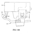
- the airbag module 22 rests on the switch assemblies 26 while engagement members 52, 54 are normally separated by a clearance C ( Figure 3E) and are only in contact, if the airbag 48 is deployed.
- the airbag cover 24 includes a plurality of switch assembly receivers 56.
- the receivers 56 each include an airbag cover engagement member 58 such as a substantially hook shaped engagement member to engage the switch assemblies 26 ( Figure 4).
- the switch assemblies 26 are preferably located proximate each spoke 14 and support the airbag cover 24.
- the switch assemblies 26 are mounted within apertures 60 formed within the molded armature 32.
- the airbag cover 24 is mounted to the airbag module 22 and is mounted in a close fitting relationship with the molded armature 32.
- the switch assemblies 26 directly engage the airbag cover 24 receivers 56 ( Figure 3A) that are located proximate the spokes 14. The component tolerance stack up is thereby minimized.
- An aesthetically pleasing fit between the airbag cover 24 and the molded armature 32 is provided which minimizes any separation line while allowing horn activation by movement of the airbag cover 24 relative to the molded armature 32.
- FIG 4 one embodiment of a switch assembly 26 is illustrated in a mounted position.
- the switch assembly includes a first switch portion 62 movable relative to a second switch portion 64.
- the first switch portion 62 includes a first switch engagement member 66 preferably including a substantially hook shaped member which engages the switch assembly receiver 56 having corresponding engagement members 58.
- the airbag module 22 is snapped onto the first switch portion 62.
- Other mounting arrangements may alternatively or additionally be provided.
- the second switch portion 64 includes engagement members 70, which fit within the apertures 60 formed in the molded armature 32.
- the second switch engagement member 70 is preferably of a substantially cylindrical design having a ramped locking shoulder 72, which is engageable with a shoulder 74 formed by an enlarged diameter 76 within the aperture 60.
- the switch assembly 26 is also preferably snapped into the armature 32.
- the biasing member 78 is a coil spring which forces (illustrated as double headed arrow F) the first switch portion 62 away from the second switch portion 64.
- the switch assemblies 26 support the airbag cover 24 and the airbag module 22.
- the first switch portion 62 includes a first hook 80 and the second switch portion 64 includes a second hook 82.
- the hooks 80,82 interact under the force of the biasing member 78 to limit movement of the first switch portion 62 relative to the second switch portion 64.
- the hooks 80,82 are illustrated as corresponding hook shaped members in the disclosed embodiment. Other hooks which limit relative movement of the switch portions 62,64 may additionally or alternatively be provided.
- a first contact 84 mounted to the first switch portion 62 is thereby movable relative to a second contact 86 mounted on the second switch portion 64.
- the first switch portion 62 is moved in the direction of arrow H toward the second switch portion 64 such that the first contact 84 will touch the second contact 86.
- a circuit illustrated by electrical connectors 88a and 88b is closed and the horn 28 is activated.
- the airbag module engagement member 52' located at the 6 o'clock position is first aligned with the armature engagement member 54' located at the 6 o'clock position ( Figure 3E).
- the airbag module 22 is tipped toward the armature engagement member 54', preferably at approximately 10 degrees below axis 19 ( Figure 1).
- the axis 19 is perpendicular to the axis 18.
- the airbag module engagement member 52' is engaged with the corresponding armature engagement member 54' and the switch assembly 26 located at the 6 o'clock position is aligned with the switch assembly receiver 56 within the airbag cover 24 ( Figure 3E).
- the airbag module 22 is then tipped toward axis 19 such that all of the first switch engagement members 66 are aligned with their corresponding airbag cover engagement members 58.
- the assembler then presses against on the airbag cover 24 proximate the spokes 14 within the airbag cover 24 until each first switch engagement member 66 engages their corresponding airbag cover engagement members 58 within the airbag cover 24.
- the armature engagement members 54 and the airbag module engagement members 52 are also engaged at this time.
- the airbag module 22 is snapped onto the switch assemblies 26 that have been previously snapped into the molded armature 32. An uncomplicated yet secure attachment arrangement is thereby provided by the present invention.
- a clearance C is formed between each armature engagement member 54 and the corresponding airbag module engagement member 52 when the module 22 is mounted to the molded armature 32.
- the module 22 rests on the switch assembly 26.
- the clearance C is approximately 1 mm. The clearance C assures that there is normally no interference between each armature engagement member 54 and the corresponding airbag module engagement members 52 that may result in undesirable noise and or vibration.
- a driver need only press on the airbag cover 24 and overcome the biasing members 78 such that the first contact 84 touches the second contact 86 ( Figure 4).
- the clearance C will slightly increase. Although there is normally a clearance C, the clearance C will be eliminated during deployment of the airbag.
- each armature engagement member 54 will engage each corresponding airbag module engagement member 52 to provide a rigid attachment between the airbag module 22 and the molded armature 32. Therefor, the switch assemblies 26 need not provide airbag module retention during airbag deployment.
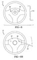
- a disassembly aperture 89 is located through the armature 30 preferably adjacent the 3 o'clock and 9 o'clock armature engagement member 54 (Figure 2A).
- the disassembly apertures 89 may be located relative to the steering column 16 ( Figure 1) and under the steering wheel assembly 10 such that the steering wheel assembly 10 must be rotated to a predefined position to access the apertures 89.
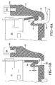
- Figure 6A is a sectional view of the steering wheel assembly 10 illustrating a method of disassembly.
- a flat bladed disassembly tool 53 is receivable through the disassembly aperture 89 ( Figure 6B).
- the tool 53 is inserted between the armature engagement member 54 and the corresponding airbag module engagement member 52.
- the tool 53 is then rotated to spread the airbag module engagement member 52 away from the armature engagement member 54.
- the module 22 is then lifted to assure disengagement of the armature engagement member 54 and corresponding airbag module engagement member 52.
- the tool 53 can then be inserted into the other disassembly apertures 89 and the process repeated.
- the airbag module 22 is tilted and lifted away from the molded armature 32 to disassemble the steering wheel assembly 10 in the reverse order of assembly as described above.
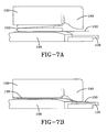
- the switch assembly 26D includes a first switch portion 130 movable relative to a second switch portion 136 while being biased by a single biasing member 132. By pressing on the airbag cover 24, the first switch portion 130 is moved in the direction of arrow H toward the second switch portion 132.
- the switch assembly 26D has a switch base 136 having a first conductor such as a metal wire 134 and a second conductor such as a metal wire 135.
- the first and second metal wires are normally insulated from one another.
- a switch base engagement member 140 secures the switch base to a steering wheel hub and a contour portion 138 extending in an opposite direction from the switch base engagement member.
- the switch base 136 has a contour portion 138 extending from the middle thereof.
- the contour portion may have openings or slots around the circumference thereof or the contour portion 138 may have a continuous surface.
- the contour portion 138 has a protrusion 137 that is used to connect the switch base 136 with the switch cap 130.
- An alignment pin 141 extends from the airbag cover 24.
- the alignment pin 141 is movable within the alignment aperture 131 in the switch cap and a corresponding passage 149 formed in the switch base.
- the alignment pin 141 and alignment apertures 131, 140 further assure that the airbag cover is stabilized and pressure thereon will be more directly exerted upon the switch assembly 26D.
- a switch connector 133 has an aperture (150) for receiving the contour portion 138 of the switch base 136.
- the switch connector 133 has an extension portion 139 that is flexible and can bend so that the extension portion 139 can contact the metal wires.
- the extension portion 139 is made from a conductive material. In the non-engaged position as seen in Figure 7A, the switch connector rests 133 flat on the switch base 136 and there is a distance separating the extension portion 139 and the metal wires 134, 135.
- a biasing member 132 preferably a coil spring is disposed between the switch cap 130 and the switch connector 133.
- the switch cap 130 is connected to the airbag cover 24.
- the biasing member 132 has a spring force associated therewith to maintain a separation between the switch cap 130 and the switch connector 133.
- An force applied on the airbag cover will cause the switch cap 130 to slide into the switch connector 133, and the end portion of the switch connector 133 will in turn bend toward the switch base 136 to close the electrical circuit.
- the switch assembly 26D is in its engaged position whereby the horn is actuated.
Landscapes
- Engineering & Computer Science (AREA)
- Mechanical Engineering (AREA)
- Physics & Mathematics (AREA)
- Acoustics & Sound (AREA)
- Air Bags (AREA)
- Steering Controls (AREA)
- Push-Button Switches (AREA)
Abstract
Description
Claims (8)
- A switch assembly (26D) comprising:a switch cap (130) engageable with an airbag cover (24);a switch connector (133) having an extension portion (139) made from an electrically conductive material;a switch base (136) having a switch base engagement member (140) for securing the switch base to a steering wheel hub (12) and a contour portion (138) extending in an opposite direction from the switch base engagement member, the switch base has a first conductor (134) insulated from a second conductor (135); anda biasing member (132) to bias the switch cap (130) from the switch connector (133) wherein the biasing member is disposed between the switch cap and the switch connector.
- A switch assembly (26D) according to claim 1 wherein the switch cap (130) has an aperture (131) for receiving the contour portion (138) of the switch base (136), the switch connector (133) has an aperture (150) for receiving the contour portion of the switch base.
- A switch assembly (26D) according to claim 1 or 2 wherein the extension portion (133) of the switch connector (133) is capable of bending in a direction towards the switch base (136).
- A switch assembly (26D) according to any of claims 1 - 3 wherein the biasing member (132) is a coil spring.
- A switch assembly (26D) according to any of claims 1 - 4 wherein the first conductor (134) and the second conductor (135) are wires.
- A switch assembly (26D) according to any of claims 1 - 5 in combination with an airbag cover (24) wherein an alignment pin (141) extends from the airbag cover, the alignment pin being movable within an alignment aperture (131) in the switch cap (130) and a corresponding passage (149) formed in the switch base (136).
- A switch assembly (26D) according to any of claims 1 - 7 wherein a force applied on the airbag cover (24) will cause the switch cap (130) to slide into the switch connector (133), and an end portion of the switch connector (133) will in turn bend toward the switch base (136) to close an electrical circuit.
- A switch assembly (26D) according to any of claims 1 - 7 in combination with a steering wheel hub (12) the switch base engagement member (140) securing the switch base (136) to the steering wheel hub.
Applications Claiming Priority (2)
| Application Number | Priority Date | Filing Date | Title |
|---|---|---|---|
| US35549402P | 2002-02-08 | 2002-02-08 | |
| US355494P | 2002-02-08 |
Publications (2)
| Publication Number | Publication Date |
|---|---|
| EP1338471A2 true EP1338471A2 (en) | 2003-08-27 |
| EP1338471A3 EP1338471A3 (en) | 2007-05-02 |
Family
ID=27663298
Family Applications (1)
| Application Number | Title | Priority Date | Filing Date |
|---|---|---|---|
| EP03002076A Withdrawn EP1338471A3 (en) | 2002-02-08 | 2003-01-30 | Switch assembly mounted in a steering wheel |
Country Status (4)
| Country | Link |
|---|---|
| US (5) | US6830263B2 (en) |
| EP (1) | EP1338471A3 (en) |
| JP (1) | JP3797617B2 (en) |
| KR (1) | KR100516267B1 (en) |
Families Citing this family (62)
| Publication number | Priority date | Publication date | Assignee | Title |
|---|---|---|---|---|
| GB2390337A (en) * | 2002-07-02 | 2004-01-07 | Autoliv Dev | Steering wheel with airbag centrally and resiliently mounted |
| KR100477245B1 (en) * | 2002-07-05 | 2005-03-17 | 현대모비스 주식회사 | air bag module having horn switch |
| DE20303388U1 (en) * | 2003-03-03 | 2003-07-10 | TRW Automotive Safety Systems GmbH, 63743 Aschaffenburg | Generator carrier for a driver gas bag module, functional module for a steering wheel of a motor vehicle, assembly from a generator carrier and a functional module, and steering wheel for a motor vehicle |
| JP2005038811A (en) * | 2003-06-30 | 2005-02-10 | Takata Corp | Horn switching device and air bag device |
| US7268309B2 (en) * | 2003-06-30 | 2007-09-11 | Takata Corporation | Horn switch gear and airbag system |
| US7159897B2 (en) * | 2003-07-21 | 2007-01-09 | Delphi Technologies, Inc. | Isolated ground for horn mechanism |
| US7055854B2 (en) * | 2004-03-03 | 2006-06-06 | Autoliv Asp, Inc. | Snap-in castanet airbag module for a vehicular steering wheel |
| JP2005313713A (en) * | 2004-04-27 | 2005-11-10 | Takata Corp | Steering device |
| EP1595754B1 (en) * | 2004-05-10 | 2008-06-04 | Key Safety Systems, Inc. | Assembly for retaining airbag modules to steering wheels |
| JP2006092921A (en) * | 2004-09-24 | 2006-04-06 | Takata Corp | Horn switch device, air-bag device and steering device |
| US7621560B2 (en) * | 2005-02-07 | 2009-11-24 | Key Safety Systems, Inc | Horn switch |
| US7380817B2 (en) * | 2005-03-29 | 2008-06-03 | Key Safety Systems, Inc. | Assembly for retaining an airbag module to a steering wheel |
| JP2006331657A (en) * | 2005-05-23 | 2006-12-07 | Piolax Inc | Horn switch device |
| KR100673405B1 (en) * | 2005-07-13 | 2007-01-24 | 지피에스코리아(주) | Packaging board for horizontally stacked thin film display panel with reinforcement means |
| DE202005013383U1 (en) * | 2005-08-24 | 2006-02-09 | Trw Automotive Safety Systems Gmbh | Vehicle steering wheel with gas bag module |
| DE202005020078U1 (en) * | 2005-12-21 | 2006-02-16 | Trw Automotive Safety Systems Gmbh | Airbag module |
| ES2301341B1 (en) * | 2006-03-13 | 2009-05-01 | Dalphi Metal España S.A. | CAR WHEEL WITH INTEGRATED AIRBAG. |
| DE102006041734B4 (en) * | 2006-09-01 | 2010-07-29 | Takata-Petri Ag | Device for fastening an airbag unit in an assembly of a motor vehicle, in particular in a steering wheel, by latching |
| KR20090050680A (en) * | 2007-11-16 | 2009-05-20 | 현대모비스 주식회사 | Steering assembly |
| US7980590B2 (en) | 2008-03-19 | 2011-07-19 | Amsafe, Inc. | Inflatable personal restraint systems having web-mounted inflators and associated methods of use and manufacture |
| US7665761B1 (en) | 2008-03-27 | 2010-02-23 | Amsafe, Inc. | Inflatable personal restraint systems and associated methods of use and manufacture |
| US20090294233A1 (en) * | 2008-06-03 | 2009-12-03 | Wayne-Ian Moore | Drive device for a hydraulic caliper brake assembly |
| DE102008028126A1 (en) * | 2008-06-13 | 2009-12-17 | Autoliv ASP, Inc., Ogden | steering wheel unit |
| US8398115B2 (en) * | 2008-06-25 | 2013-03-19 | Autoliv Development Ab | Vehicle steering wheel |
| JP5353212B2 (en) * | 2008-12-02 | 2013-11-27 | タカタ株式会社 | Mounting structure of air bag device for driver's seat and steering wheel |
| WO2010102088A2 (en) * | 2009-03-06 | 2010-09-10 | Henry Line | Rotary switch |
| KR101451126B1 (en) | 2009-09-03 | 2014-10-15 | 현대자동차주식회사 | Mounting structure of airbag module |
| US20110120823A1 (en) * | 2009-11-20 | 2011-05-26 | Charles Hansen | Retracta Belt Brake System |
| KR200458066Y1 (en) * | 2009-12-18 | 2012-01-18 | 삼일화학주식회사 | Packaging Tool for Flat Panel Display |
| US8939466B2 (en) | 2010-02-23 | 2015-01-27 | Judco Partnership, Llc | Airbag frame apparatus |
| US8491003B2 (en) | 2010-02-23 | 2013-07-23 | Judco Manufacturing, Inc. | Airbag frame apparatus |
| JP5582846B2 (en) * | 2010-03-31 | 2014-09-03 | 日本プラスト株式会社 | handle |
| WO2012026276A1 (en) * | 2010-08-26 | 2012-03-01 | オートリブ ディベロップメント エービー | Attachment structure for driver seat airbag device |
| US8469397B2 (en) | 2011-04-13 | 2013-06-25 | Amsafe, Inc. | Stitch patterns for restraint-mounted airbags and associated systems and methods |
| US8658929B2 (en) * | 2011-06-15 | 2014-02-25 | Osram Sylvania Inc. | Switch |
| US8439398B2 (en) | 2011-07-29 | 2013-05-14 | Amsafe, Inc. | Inflator connectors for inflatable personal restraints and associated systems and methods |
| JP5780671B2 (en) * | 2011-10-31 | 2015-09-16 | タカタ株式会社 | Airbag device |
| US8242392B1 (en) | 2011-11-01 | 2012-08-14 | John Ondracek | Multi-directional momentum-change sensor and methods of use |
| WO2013070905A1 (en) * | 2011-11-09 | 2013-05-16 | Key Safety Systems Inc. | Snap in driver side airbag module assembly |
| KR101462041B1 (en) | 2011-11-15 | 2014-11-19 | 에스케이이노베이션 주식회사 | Pouch type secondary battery |
| US9511866B2 (en) | 2012-03-19 | 2016-12-06 | Amsafe, Inc. | Structure mounted airbag assemblies and associated systems and methods |
| US8523220B1 (en) | 2012-03-19 | 2013-09-03 | Amsafe, Inc. | Structure mounted airbag assemblies and associated systems and methods |
| GB2512892A (en) * | 2013-04-10 | 2014-10-15 | Ford Global Tech Llc | A method and apparatus for attaching a driver airbag module to a steering wheel |
| JP6185798B2 (en) * | 2013-05-07 | 2017-08-23 | 日本プラスト株式会社 | Steering wheel |
| DE102013008819B4 (en) * | 2013-05-25 | 2020-07-23 | Autoliv Development Ab | Steering wheel unit |
| EP2907700B1 (en) * | 2014-02-17 | 2021-07-21 | Dalphi Metal España, S.A. | Horn system |
| EP2910425B1 (en) * | 2014-02-20 | 2020-08-05 | Dalphi Metal España, S.A. | Horn circuit |
| DE202014002194U1 (en) | 2014-03-13 | 2015-06-17 | Dalphi Metal Espana, S.A. | Connector component for attaching a gas bag module to a steering wheel, positioning sleeve therefor, set with such a connector component and a positioning sleeve and steering wheel, gas bag module and steering wheel assembly |
| US9352839B2 (en) | 2014-10-02 | 2016-05-31 | Amsafe, Inc. | Active positioning airbag assembly and associated systems and methods |
| US9944245B2 (en) | 2015-03-28 | 2018-04-17 | Amsafe, Inc. | Extending pass-through airbag occupant restraint systems, and associated systems and methods |
| US9925950B2 (en) | 2015-04-11 | 2018-03-27 | Amsafe, Inc. | Active airbag vent system |
| EP3178707B1 (en) * | 2015-12-08 | 2018-07-18 | Autoliv Development AB | Steering wheel |
| US10604259B2 (en) | 2016-01-20 | 2020-03-31 | Amsafe, Inc. | Occupant restraint systems having extending restraints, and associated systems and methods |
| DE102016005020B4 (en) * | 2016-04-26 | 2019-08-14 | Dalphi Metal Espana, S.A. | Airbag unit and vehicle occupant safety system with such a gas bag unit and manufacturing method |
| WO2018044254A1 (en) * | 2016-08-29 | 2018-03-08 | Trw Vehicle Safety Systems Inc. | Driver airbag mounting verification system |
| KR102394806B1 (en) | 2017-11-29 | 2022-05-04 | 현대자동차주식회사 | Device for operating horn of vehicle |
| DE202018103719U1 (en) * | 2018-06-29 | 2019-10-09 | Dalphi Metal Espana, S.A. | Airbag module for a vehicle occupant restraint system and steering wheel assembly with such a gas bag module |
| FR3083189B1 (en) * | 2018-06-29 | 2021-12-10 | Autoliv Dev | REMOVABLE MOUNTING DEVICE FOR AN INFLATABLE CUSHION MODULE |
| KR102882426B1 (en) * | 2020-08-11 | 2025-11-06 | 현대자동차주식회사 | Steering wheel |
| CN115871767A (en) * | 2021-09-29 | 2023-03-31 | 奥托立夫开发公司 | Steering wheel and method for starting preset function in vehicle by using steering wheel |
| DE102022122054A1 (en) * | 2022-08-31 | 2024-02-29 | Autoliv Development Ab | Steering wheel with an airbag module |
| KR20240033489A (en) * | 2022-09-05 | 2024-03-12 | 현대자동차주식회사 | Steering wheel and damper unit of the steering wheel |
Family Cites Families (48)
| Publication number | Priority date | Publication date | Assignee | Title |
|---|---|---|---|---|
| US4434338A (en) * | 1982-01-22 | 1984-02-28 | Rood Robert M | Coil spring switch |
| US4525607A (en) * | 1983-02-04 | 1985-06-25 | Yasutaka Senoh | Simplified electric switch construction |
| US4899020A (en) * | 1987-10-19 | 1990-02-06 | Toyoda Gosei Co., Ltd. | Printed wiring unit for horn switch |
| US4933522A (en) * | 1989-03-07 | 1990-06-12 | Itt Corporation | Flanged snap dome |
| US5120923A (en) * | 1989-10-06 | 1992-06-09 | Takafumi Kato | Push button switch |
| US5201824A (en) * | 1989-10-06 | 1993-04-13 | Alps Electric Co., Ltd. | Push button switch |
| JP2557557Y2 (en) * | 1991-02-12 | 1997-12-10 | ミネベア株式会社 | Key switch |
| US5303952A (en) * | 1992-12-23 | 1994-04-19 | United Technologies Automotive, Inc. | Electric signalling in a supplemental vehicle restraint system |
| US5327796A (en) * | 1992-12-28 | 1994-07-12 | General Motors Corporation | Horn switch actuated by rocking air bag module |
| US5386091A (en) * | 1993-04-08 | 1995-01-31 | Compaq Computer Corporation | Low profile keyswitch |
| US5333897A (en) * | 1993-10-25 | 1994-08-02 | General Motors Corporation | Snap lock pin inflatable restraint module mounting mechanism |
| US5627352A (en) * | 1994-09-28 | 1997-05-06 | Toyoda Gosei Co., Ltd. | Steering wheel |
| JPH08207783A (en) * | 1994-12-07 | 1996-08-13 | Toyoda Gosei Co Ltd | Steering wheel |
| WO1996038326A1 (en) * | 1995-05-31 | 1996-12-05 | Alliedsignal Inc. | Snap-on steering wheel with integral airbag housing |
| US5599039A (en) * | 1995-07-21 | 1997-02-04 | Textron Inc. | Spring retainer air bag mounting device |
| US5710397A (en) * | 1995-08-04 | 1998-01-20 | Acer Peripherals, Inc. | Switch actuator for membrane switch |
| JPH09175409A (en) * | 1995-12-27 | 1997-07-08 | Toyoda Gosei Co Ltd | Method for installing steering wheel |
| DE69725246T2 (en) * | 1996-08-06 | 2004-07-29 | Toyoda Gosei Co., Ltd., Haruhi | steering wheel |
| US5738369A (en) * | 1996-10-09 | 1998-04-14 | Breed Automotive Technology, Inc. | Snap-on air bag and horn switch module |
| DE19724029A1 (en) * | 1997-06-06 | 1998-12-24 | Takata Europ Gmbh | Airbag device |
| DE29720079U1 (en) * | 1997-11-12 | 1998-07-02 | Trw Occupant Restraint Systems Gmbh, 73551 Alfdorf | Vehicle steering wheel with integrated gas bag module |
| DE19802292C1 (en) * | 1998-01-22 | 1999-08-26 | Rafi Gmbh & Co Kg Elektrotechn | Push button |
| DE29805207U1 (en) * | 1998-03-23 | 1998-06-04 | TRW Automotive Safety Systems GmbH, 63743 Aschaffenburg | Steering wheel with an airbag |
| DE29805210U1 (en) * | 1998-03-23 | 1998-06-04 | TRW Automotive Safety Systems GmbH, 63743 Aschaffenburg | Impact protection device |
| JP2000112621A (en) * | 1998-09-30 | 2000-04-21 | Alps Electric Co Ltd | Key switch |
| JP2000322974A (en) * | 1999-05-10 | 2000-11-24 | Alps Electric Co Ltd | Press button switch |
| DE19927032A1 (en) * | 1999-06-04 | 2000-12-14 | Petri Ag | Arrangement for locking an airbag module with a steering wheel |
| IT1308842B1 (en) * | 1999-09-24 | 2002-01-11 | Gallino Plasturgia S R L | OPERATOR DEVICE FOR HORN WARNING FOR A DIACTION WHEEL. |
| US6156986A (en) * | 1999-12-30 | 2000-12-05 | Jing Mold Enterprise Co., Ltd. | Computer key switch |
| JP4581244B2 (en) * | 2000-01-14 | 2010-11-17 | タカタ株式会社 | Airbag device and steering wheel |
| US6300582B1 (en) * | 2000-02-11 | 2001-10-09 | Silitek Corporation | Dustproof and droplet-proof keyswitch |
| JP4538956B2 (en) * | 2000-03-17 | 2010-09-08 | タカタ株式会社 | Airbag device |
| US6276711B1 (en) * | 2000-03-27 | 2001-08-21 | Breed Automotive Technology, Inc. | Quick disconnect feature for snap-in driver air bag module |
| US6204462B1 (en) * | 2000-03-28 | 2001-03-20 | Silitek Corporation | Stable keyswitch |
| JP2001278060A (en) * | 2000-03-30 | 2001-10-10 | Nippon Plast Co Ltd | Horn device for steering wheel |
| JP4635293B2 (en) * | 2000-04-07 | 2011-02-23 | タカタ株式会社 | Airbag device |
| EP1418095B1 (en) * | 2000-06-27 | 2006-04-26 | Toyoda Gosei Co., Ltd. | Steering wheel with an airbag device |
| JP2002093273A (en) * | 2000-09-18 | 2002-03-29 | Tokai Rika Co Ltd | Mounting structure of handle switch for vehicle |
| DE20017527U1 (en) * | 2000-10-12 | 2001-02-22 | TRW Automotive Safety Systems GmbH & Co. KG, 63743 Aschaffenburg | Vehicle steering wheel |
| DE20021532U1 (en) * | 2000-12-20 | 2001-04-26 | TRW Automotive Safety Systems GmbH & Co. KG, 63743 Aschaffenburg | Vehicle steering wheel |
| JP2002216580A (en) * | 2001-01-18 | 2002-08-02 | Alps Electric Co Ltd | Contact plate, contact-plate-attached sheet, and switch device using them |
| ITTO20010784A1 (en) * | 2001-08-03 | 2003-02-03 | Breed Automotive Tech | HORSE WARNING DEVICE FOR A VEHICLE STEERING WHEEL. |
| JP4039030B2 (en) * | 2001-10-29 | 2008-01-30 | 松下電器産業株式会社 | Push-on switch |
| JP3753676B2 (en) * | 2002-05-31 | 2006-03-08 | 不二電子工業株式会社 | switch |
| EP1393991B1 (en) * | 2002-08-27 | 2006-05-24 | TRW Automotive Safety Systems GmbH | Airbag Module |
| DE20218740U1 (en) * | 2002-12-04 | 2003-04-10 | TRW Automotive Safety Systems GmbH & Co. KG, 63743 Aschaffenburg | Airbag module |
| JP2004241140A (en) * | 2003-02-03 | 2004-08-26 | Alps Electric Co Ltd | Switching device |
| US6942247B2 (en) * | 2003-03-12 | 2005-09-13 | Delphi Technologies, Inc. | Driver airbag formed contact spring |
-
2003
- 2003-01-13 US US10/340,670 patent/US6830263B2/en not_active Expired - Lifetime
- 2003-01-13 US US10/340,671 patent/US6840537B2/en not_active Expired - Lifetime
- 2003-01-13 US US10/340,672 patent/US6860509B2/en not_active Expired - Lifetime
- 2003-01-30 EP EP03002076A patent/EP1338471A3/en not_active Withdrawn
- 2003-02-07 KR KR10-2003-0007669A patent/KR100516267B1/en not_active Expired - Fee Related
- 2003-02-10 JP JP2003031972A patent/JP3797617B2/en not_active Expired - Fee Related
-
2004
- 2004-12-01 US US10/999,462 patent/US6953204B2/en not_active Expired - Lifetime
- 2004-12-01 US US10/999,482 patent/US7121581B2/en not_active Expired - Fee Related
Also Published As
| Publication number | Publication date |
|---|---|
| US6840537B2 (en) | 2005-01-11 |
| US20050093275A1 (en) | 2005-05-05 |
| US20030151236A1 (en) | 2003-08-14 |
| KR100516267B1 (en) | 2005-09-21 |
| US20050200104A1 (en) | 2005-09-15 |
| EP1338471A3 (en) | 2007-05-02 |
| US6860509B2 (en) | 2005-03-01 |
| JP2003261034A (en) | 2003-09-16 |
| US20030155752A1 (en) | 2003-08-21 |
| US6830263B2 (en) | 2004-12-14 |
| JP3797617B2 (en) | 2006-07-19 |
| KR20030067565A (en) | 2003-08-14 |
| US6953204B2 (en) | 2005-10-11 |
| US7121581B2 (en) | 2006-10-17 |
| US20030151237A1 (en) | 2003-08-14 |
Similar Documents
| Publication | Publication Date | Title |
|---|---|---|
| EP1338471A2 (en) | Switch assembly mounted in a steering wheel | |
| US6675675B1 (en) | Steering wheel | |
| US6312012B1 (en) | Steering wheel with integrated gas bag | |
| US6196573B1 (en) | Mounting mechanism for inflatable restraint system | |
| US7159897B2 (en) | Isolated ground for horn mechanism | |
| US6086090A (en) | Vehicle steering wheel with integrated gas bag module | |
| US7490852B2 (en) | Apparatus and method for providing a horn contact mechanism | |
| US5235146A (en) | Steering wheel horn switch arrangement | |
| US6942247B2 (en) | Driver airbag formed contact spring | |
| WO2001072558A1 (en) | Snap-in driver's airbag module | |
| CN101817332A (en) | Steering wheel device with air bag | |
| US10899301B2 (en) | Assembly of a driver airbag module and a steering wheel | |
| EP1720740B1 (en) | Snap-in castanet airbag module for a vehicular steering wheel | |
| US20020096865A1 (en) | Driver air bag module horn with improved assembly and functionality characteristics | |
| WO2008051117A1 (en) | A horn-actuator and a safety arrangement for a motor vehicle comprising a horn-actuator | |
| US20100059974A1 (en) | Safety arrangement | |
| US7422236B2 (en) | Apparatus and method for providing a horn contact mechanism | |
| US5593177A (en) | Airbag module electric component attachment using studs | |
| JP3276508B2 (en) | Steering wheel | |
| JP2561777B2 (en) | Steering wheel horn switch device | |
| JP2002283943A (en) | Steering wheel | |
| JP3439336B2 (en) | Airbag device and steering wheel | |
| JPH08253099A (en) | Steering wheel | |
| JPH10129388A (en) | Cover body for air bag device | |
| JPH09142244A (en) | Driver airbag module |
Legal Events
| Date | Code | Title | Description |
|---|---|---|---|
| PUAI | Public reference made under article 153(3) epc to a published international application that has entered the european phase |
Free format text: ORIGINAL CODE: 0009012 |
|
| AK | Designated contracting states |
Designated state(s): AT BE BG CH CY CZ DE DK EE ES FI FR GB GR HU IE IT LI LU MC NL PT SE SI SK TR |
|
| AX | Request for extension of the european patent |
Extension state: AL LT LV MK RO |
|
| RAP1 | Party data changed (applicant data changed or rights of an application transferred) |
Owner name: KEY SAFETY SYSTEMS, INC. |
|
| PUAL | Search report despatched |
Free format text: ORIGINAL CODE: 0009013 |
|
| AK | Designated contracting states |
Kind code of ref document: A3 Designated state(s): AT BE BG CH CY CZ DE DK EE ES FI FR GB GR HU IE IT LI LU MC NL PT SE SI SK TR |
|
| AX | Request for extension of the european patent |
Extension state: AL LT LV MK RO |
|
| AKX | Designation fees paid | ||
| REG | Reference to a national code |
Ref country code: DE Ref legal event code: 8566 |
|
| STAA | Information on the status of an ep patent application or granted ep patent |
Free format text: STATUS: THE APPLICATION IS DEEMED TO BE WITHDRAWN |
|
| 18D | Application deemed to be withdrawn |
Effective date: 20071105 |