EP1338451B1 - Elektrische Luftheizungsvorrichtung insbesondere für ein Kraftfahrzeug - Google Patents
Elektrische Luftheizungsvorrichtung insbesondere für ein Kraftfahrzeug Download PDFInfo
- Publication number
- EP1338451B1 EP1338451B1 EP03001631A EP03001631A EP1338451B1 EP 1338451 B1 EP1338451 B1 EP 1338451B1 EP 03001631 A EP03001631 A EP 03001631A EP 03001631 A EP03001631 A EP 03001631A EP 1338451 B1 EP1338451 B1 EP 1338451B1
- Authority
- EP
- European Patent Office
- Prior art keywords
- housing
- heating elements
- heating
- heating device
- electrical
- Prior art date
- Legal status (The legal status is an assumption and is not a legal conclusion. Google has not performed a legal analysis and makes no representation as to the accuracy of the status listed.)
- Expired - Lifetime
Links
Images



Classifications
-
- F—MECHANICAL ENGINEERING; LIGHTING; HEATING; WEAPONS; BLASTING
- F24—HEATING; RANGES; VENTILATING
- F24H—FLUID HEATERS, e.g. WATER OR AIR HEATERS, HAVING HEAT-GENERATING MEANS, e.g. HEAT PUMPS, IN GENERAL
- F24H3/00—Air heaters
- F24H3/02—Air heaters with forced circulation
- F24H3/04—Air heaters with forced circulation the air being in direct contact with the heating medium, e.g. electric heating element
- F24H3/0405—Air heaters with forced circulation the air being in direct contact with the heating medium, e.g. electric heating element using electric energy supply, e.g. the heating medium being a resistive element; Heating by direct contact, i.e. with resistive elements, electrodes and fins being bonded together without additional element in-between
- F24H3/0429—For vehicles
-
- F—MECHANICAL ENGINEERING; LIGHTING; HEATING; WEAPONS; BLASTING
- F24—HEATING; RANGES; VENTILATING
- F24H—FLUID HEATERS, e.g. WATER OR AIR HEATERS, HAVING HEAT-GENERATING MEANS, e.g. HEAT PUMPS, IN GENERAL
- F24H3/00—Air heaters
- F24H3/02—Air heaters with forced circulation
- F24H3/04—Air heaters with forced circulation the air being in direct contact with the heating medium, e.g. electric heating element
- F24H3/0405—Air heaters with forced circulation the air being in direct contact with the heating medium, e.g. electric heating element using electric energy supply, e.g. the heating medium being a resistive element; Heating by direct contact, i.e. with resistive elements, electrodes and fins being bonded together without additional element in-between
- F24H3/0429—For vehicles
- F24H3/0435—Structures comprising heat spreading elements in the form of fins
-
- F—MECHANICAL ENGINEERING; LIGHTING; HEATING; WEAPONS; BLASTING
- F24—HEATING; RANGES; VENTILATING
- F24H—FLUID HEATERS, e.g. WATER OR AIR HEATERS, HAVING HEAT-GENERATING MEANS, e.g. HEAT PUMPS, IN GENERAL
- F24H3/00—Air heaters
- F24H3/02—Air heaters with forced circulation
- F24H3/04—Air heaters with forced circulation the air being in direct contact with the heating medium, e.g. electric heating element
- F24H3/0405—Air heaters with forced circulation the air being in direct contact with the heating medium, e.g. electric heating element using electric energy supply, e.g. the heating medium being a resistive element; Heating by direct contact, i.e. with resistive elements, electrodes and fins being bonded together without additional element in-between
- F24H3/0429—For vehicles
- F24H3/0441—Interfaces between the electrodes of a resistive heating element and the power supply means
-
- F—MECHANICAL ENGINEERING; LIGHTING; HEATING; WEAPONS; BLASTING
- F24—HEATING; RANGES; VENTILATING
- F24H—FLUID HEATERS, e.g. WATER OR AIR HEATERS, HAVING HEAT-GENERATING MEANS, e.g. HEAT PUMPS, IN GENERAL
- F24H3/00—Air heaters
- F24H3/02—Air heaters with forced circulation
- F24H3/04—Air heaters with forced circulation the air being in direct contact with the heating medium, e.g. electric heating element
- F24H3/0405—Air heaters with forced circulation the air being in direct contact with the heating medium, e.g. electric heating element using electric energy supply, e.g. the heating medium being a resistive element; Heating by direct contact, i.e. with resistive elements, electrodes and fins being bonded together without additional element in-between
- F24H3/0429—For vehicles
- F24H3/0441—Interfaces between the electrodes of a resistive heating element and the power supply means
- F24H3/0447—Forms of the electrode terminals, e.g. tongues or clips
-
- F—MECHANICAL ENGINEERING; LIGHTING; HEATING; WEAPONS; BLASTING
- F24—HEATING; RANGES; VENTILATING
- F24H—FLUID HEATERS, e.g. WATER OR AIR HEATERS, HAVING HEAT-GENERATING MEANS, e.g. HEAT PUMPS, IN GENERAL
- F24H9/00—Details
- F24H9/18—Arrangement or mounting of grates or heating means
- F24H9/1809—Arrangement or mounting of grates or heating means for water heaters
- F24H9/1818—Arrangement or mounting of electric heating means
-
- F—MECHANICAL ENGINEERING; LIGHTING; HEATING; WEAPONS; BLASTING
- F24—HEATING; RANGES; VENTILATING
- F24H—FLUID HEATERS, e.g. WATER OR AIR HEATERS, HAVING HEAT-GENERATING MEANS, e.g. HEAT PUMPS, IN GENERAL
- F24H9/00—Details
- F24H9/18—Arrangement or mounting of grates or heating means
- F24H9/1854—Arrangement or mounting of grates or heating means for air heaters
- F24H9/1863—Arrangement or mounting of electric heating means
- F24H9/1872—PTC resistor
-
- F—MECHANICAL ENGINEERING; LIGHTING; HEATING; WEAPONS; BLASTING
- F24—HEATING; RANGES; VENTILATING
- F24H—FLUID HEATERS, e.g. WATER OR AIR HEATERS, HAVING HEAT-GENERATING MEANS, e.g. HEAT PUMPS, IN GENERAL
- F24H3/00—Air heaters
- F24H3/02—Air heaters with forced circulation
- F24H3/06—Air heaters with forced circulation the air being kept separate from the heating medium, e.g. using forced circulation of air over radiators
- F24H3/062—Air heaters with forced circulation the air being kept separate from the heating medium, e.g. using forced circulation of air over radiators using electric energy supply; the heating medium being the resistive element
Definitions
- the invention relates to an electric air heating device in particular for a motor vehicle with electric Heating elements for heating the air and a housing, the one ground connection, an electrical supply connection and an electronic circuit for controlling the Supplying the heating elements and on which the heating elements in electrical contact with the ground terminal and the electrical supply connection are arranged
- a device of this kind is e.g. from the WO 02/057100 known.
- Such an electric air heating device in the electrical heating elements formed from PTC heating rods are, is known per se.
- the housing consists of a plastic material, in which the heating elements via a potting compound in an electrical contact via the electronic circuit with the electrical supply connection on the one hand and via a ground plate and one in electrical connection standing ground bolt with the ground connection on the other hand are connected.
- the thermal and the mechanical connection between the housing, the electronic circuit and the heating elements by means realized several components, where it is necessary for high tolerance compensation with additional fillers such as To provide adhesives and sealing compounds.
- the adhesives and the sealing compounds take over the actual Abdichtfunktion also the task, occurring forces and Record moments of the heating device. It is, however the seal and connection between the housing Made of plastic and the heating elements, usually made of Alumium mecanicstäben are formed, not easily processable and process-reliable. The required life can not be guaranteed so far.
- the forces occurring proportionately passed through to the contact of the circuit board, on which the electronic circuit is provided This passage can lead to mechanical loads the circuit board come with a high risk of damage the electronic components is connected.
- the object underlying the invention is in contrast, therein, an electric air heating device of the type mentioned above, with a lower Number of components, especially in the area of their Housing gets by.
- the housing made of an electrically conductive material exists and formed in one piece with the ground terminal is, the ground potential is due to the housing, so this not only the housing function but also the function of the in the known heating device existing ground plate, of ground bolt and ground connection for the customer Adaptation fulfilled.
- Ground plate, the ground bolt and the potting compounds, at the known heating device provided as separate components are, in the heating device according to the invention omitted.
- Heating device have the particular advantage that the heat conduction and heat dissipation from the electronic circuit and the circuit breaker supporting Circuit board in the heating area is possible that a heat exchange without loss of area due to proportional heat transfer possible through housing breakthroughs with weight optimization is, and that the mechanical fastening of all components, the attachment of the circuit board, the entire grounding the heating device, and the direct ground contact protected against reverse polarity via the molded on the housing Ground connection can be made for a customer-side cable.
- Manufacturing technology results in the advantages that due to the smaller number of components the number the production steps in series production is smaller and that processable processes can be used.
- the mechanical heat transfer interfaces for the heat energy removal from the circuit breakers in the heating areas easier and becomes the heat the circuit breaker directly across the housing into the actual Heated area dissipated, while the ground contact with reverse polarity protection via the ground connection and the absorption of forces and moments from the heating area are possible without additional components provided are.
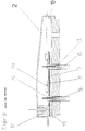
- a electric air heating device in particular for a Motor vehicle consists essentially of electrical heating elements 3, on the one hand to an abutment 4 and on the other are arranged on a housing 1, of a Housing cover 2 is closed.
- Fig. 2 As shown in detail in Fig. 2, exist the heating elements 3 of heating rods 3b, with PTC components are filled. As shown in Fig. 6 are located 3b in the rods 3b reeds 3c, wherein the rods 3b one-sided represent the external connection. On the bars 3b Lamella 3a are mounted, which in the case of an electric Supply of the rods 3b resulting heat to the ambient air submit. The counter-bearing 4 is on the heating elements. 3 mounted and on the outer terminal side of the heating elements. 3 sealing elements 6 are inserted for sealing, through which the contact tongues 3c survive. The heating elements 3 are on the housing 1 pressed.
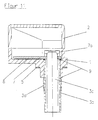
- the housing 1 consists of an electrically conductive Material, in particular of aluminum, and is in the in FIG. 6 manner in one piece with molded ground terminal 1a formed in the form of a mass dome.
- the heating elements 3b are about the housing 1 and the Massedom 1a with the ground connection 1b in conjunction, according to customer requirements can be executed, and are with their contact tongues 3c via a printed circuit board 7a equipped with circuit breakers 7a connected to the electrical supply connection that the electronic circuit for controlling the electrical supply the heating elements 3 carries.
- the ground connection 1b shown in the drawing Massedom 1a of the housing 1 is in the form of a screw-in However, he can also as an insert or Einpressteil be designed or constructive integrated or in a hole in Massedom 1a by means of a Be fixed screw.
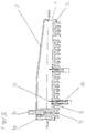
- Embodiment of the heating device according to the invention are missing in the first embodiment provided Sealing elements 6 and are the heating elements 3b instead via a welded joint 9 with or without additives the housing 1 welded.
- the corresponding weld, formed after the mounting of the housing 1 on the rods 3a can be, to the inside or outside of the case 1, wherein a welding of both Positions is also possible, as shown in Figs. 9 and 11 is shown.
- a formed from a plastic material Gesimousedekkel 2 completes the basic structure.
- Cooling fins 1c provided in one piece with the housing 1 are formed.
- one-piece Housing 1 made of an electrically conductive material, especially made of aluminum, assumes the functions of a Housing, namely the protection of electronic circuits, the provision of a flange to the air box and the mechanically stable reception of the bars 3b, a ground plate, the recording of the circuit board, the discharge of the Circuit breakers 7a developed heating energy to the heating elements 3, the mechanically stable reception of the rods 3b, the grounding of the circuit board 7 and the heating elements 3 and a mass dome, namely the ground contact the circuit board 7, the heating elements 3 and the ground terminal 3b with possible reverse polarity protection to the positive connection in the form of a single component.
- both housing parts namely the housing cover 2 and the housing body 10 of a Made of plastic material and are separately a ground stud 12, a ground plate 11 and a potting compound 13 are provided, taken over the heating elements 3b in the housing 10 are.
- the housing 1 is in the heating device according to the invention but not only the transported heat energy to the Schuelementober Design from, proportionately, the heat energy through the integrated housing ribs 1c also directly supplied to the ambient air.
- a possible release of mechanical clamping connections, which are provided in the known heating device, at occurring temperature changes is by the one-piece Training of the housing 1 prevents, in which the rods 3b are pressed to the ground connection 1b.
- the earth connection 1b can be used for reverse polarity protection both connections as self-tapping screw, via a standard threaded connection or integrated each be designed according to customer requirements. Stress by moments, in the later assembly and use of the ground connection cable occur are disconnected from the circuit board 7.
- the ground contact of the rods 3b of the heating elements. 3 to the ground connection 1b is thus directly over the housing 1a, interfaces between a ground plate connected to the Heating rods is clamped, to ground plate and between the am Ground plate fastened ground bolt omitted.
- the seal is made by the form-fitting by the before Pressing the rods (3b) mounted sealing elements (6) or through the circumferential weld.
- sealants such as a silicone bead and potting compounds omitted and unnecessary
Landscapes
- Engineering & Computer Science (AREA)
- Physics & Mathematics (AREA)
- Thermal Sciences (AREA)
- Chemical & Material Sciences (AREA)
- Combustion & Propulsion (AREA)
- Mechanical Engineering (AREA)
- General Engineering & Computer Science (AREA)
- Air-Conditioning For Vehicles (AREA)
- Control Of Resistance Heating (AREA)
Description
Claims (7)
- Elektrische Luftheizungsvorrichtung insbesondere für ein Kraftfahrzeug mitdadurch gekennzeichnet, dasselektrischen Heizelementen (3) zum Erwärmen der Luft undeinem Gehäuse (1), das einen Masseanschluss (1b), einen elektrischen Versorgungsanschluss und eine elektronische Schaltung (7) zur Steuerung der elektrischen Versorgung der Heizelemente aufweist und an dem die Heizelemente in elektrischem Kontakt mit dem Masseanschluss (1b) und dem elektrischen Versorgungsanschluss angeordnet sind,
das Gehäuse (1) aus einem elektrisch leitenden Material und in einem Stück mit angeformtem Masseanschluss (1a) ausgebildet ist und die Heizelemente (3) und die elektronische Schaltung (7) in direktem elektrischen Kontakt mit dem Gehäuse (1) angeordnet sind. - Heizungsvorrichtung nach Anspruch 1, dadurch gekennzeichnet, dass die Heizelemente (3) in das Gehäuse (1) eingepresst sind.
- Heizungsvorrichtung nach Anspruch 1 oder 2, dadurch gekennzeichnet, dass die Heizelemente (3) über ein Dichtungselement (6) im Gehäuse (1) angeordnet sind.
- Heizungsvorrichtung nach Anspruch 1 oder 2, dadurch gekennzeichnet, dass die Heizelemente (3) im Gehäuse (1) montiert und mit dem Gehäuse (1) verschweißt sind.
- Heizungsvorrichtung nach einem der Ansprüche 1 bis 4, dadurch gekennzeichnet, dass zwischen einer Leiterplatte (7), die die elektronische Schaltung zum Steuern der elektrischen Versorgung der Heizelemente (3) trägt, und dem Gehäuse (1) eine Wärmeleitmaterialschicht (8) angeordnet ist.
- Heizungsvorrichtung nach einem der vorhergehenden Ansprüche, dadurch gekennzeichnet, dass an der den Heizelementen (3) zugewandten Seite des Gehäuses (1) Kühlrippen (1c) in einem Stück mit dem Gehäuse (1) ausgebildet sind.
- Heizungsvorrichtung nach einem der vorhergehenden Ansprüche, dadurch gekennzeichnet, dass das Gehäuse aus Aluminium oder einer Aluminiumlegierung gebildet ist.
Applications Claiming Priority (2)
| Application Number | Priority Date | Filing Date | Title |
|---|---|---|---|
| DE10208103A DE10208103A1 (de) | 2002-02-26 | 2002-02-26 | Elektrische Luftheizungsvorrichtung insbesondere für ein Kraftfahrzeug |
| DE10208103 | 2002-02-26 |
Publications (3)
| Publication Number | Publication Date |
|---|---|
| EP1338451A2 EP1338451A2 (de) | 2003-08-27 |
| EP1338451A3 EP1338451A3 (de) | 2004-04-21 |
| EP1338451B1 true EP1338451B1 (de) | 2005-04-27 |
Family
ID=27635310
Family Applications (1)
| Application Number | Title | Priority Date | Filing Date |
|---|---|---|---|
| EP03001631A Expired - Lifetime EP1338451B1 (de) | 2002-02-26 | 2003-01-24 | Elektrische Luftheizungsvorrichtung insbesondere für ein Kraftfahrzeug |
Country Status (7)
| Country | Link |
|---|---|
| US (1) | US6810203B2 (de) |
| EP (1) | EP1338451B1 (de) |
| JP (1) | JP4908729B2 (de) |
| AT (1) | ATE294364T1 (de) |
| CA (1) | CA2418591C (de) |
| DE (2) | DE10208103A1 (de) |
| ES (1) | ES2237718T3 (de) |
Families Citing this family (43)
| Publication number | Priority date | Publication date | Assignee | Title |
|---|---|---|---|---|
| DE10102671C2 (de) * | 2001-01-17 | 2003-12-24 | Eichenauer Heizelemente Gmbh | Elektrische Heizung für ein Kraftfahrzeug |
| FR2838599B1 (fr) * | 2002-04-11 | 2004-08-06 | Valeo Climatisation | Dispositif de chauffage electrique, notamment pour appareil de chauffage et ou climatisation de vehicule |
| FR2855933B1 (fr) * | 2003-06-06 | 2006-06-09 | Valeo Climatisation | Dispositif de chauffage electrique, notamment pour un vehicule automobile |
| FR2859349B1 (fr) † | 2003-08-29 | 2006-12-01 | Valeo Climatisation | Element de chauffage electrique pour appareil de ventilation, de chauffage et/ou de climatisation d'habitacle |
| FR2868737B1 (fr) * | 2004-04-13 | 2008-08-08 | Valeo Climatisation Sa | Ensemble de chauffage pour installation de chauffage, de ventilation et/ou d'air climatise d'un habitacle de vehicule |
| FR2878316B1 (fr) * | 2004-11-25 | 2007-03-16 | Valeo Climatisation Sa | Dispositif de chauffage electrique, notamment pour appareil de chauffage, de ventilation et/ou de climatisation de vehicule |
| DE502005005264D1 (de) * | 2005-07-26 | 2008-10-16 | Behr France Rouffach Sas | Heizungsanordnung mit PCT-Element, insbesondere für ein Kraftfahrzeug |
| EP1963753B1 (de) * | 2005-12-20 | 2016-06-08 | BorgWarner Ludwigsburg GmbH | Elektrische heizvorrichtung, insbesondere für automobile |
| US8981264B2 (en) | 2006-02-17 | 2015-03-17 | Phillips & Temro Industries Inc. | Solid state switch |
| US8003922B2 (en) * | 2006-02-17 | 2011-08-23 | Phillips & Temro Industries Inc. | Solid state switch with over-temperature and over-current protection |
| DE102006055872B3 (de) * | 2006-11-23 | 2008-03-13 | Eichenauer Heizelemente Gmbh & Co. Kg | Elektrische Heizung, insbesondere zur Verwendung als Zusatzheizung in Automobilen |
| JP4940942B2 (ja) * | 2006-12-26 | 2012-05-30 | 株式会社デンソー | 車両用空調装置 |
| DE202007001079U1 (de) * | 2007-01-18 | 2008-05-21 | Eichenauer Heizelemente Gmbh & Co. Kg | Kraftfahrzeugheizung |
| EP2017545B1 (de) * | 2007-07-18 | 2012-04-25 | Eberspächer catem GmbH & Co. KG | Elektrische Heizvorrichtung |
| DE502007005351D1 (de) | 2007-07-20 | 2010-11-25 | Eberspaecher Catem Gmbh & Co K | Elektrische Heizvorrichtung insbesondere für Kraftfahrzeuge |
| US7723652B2 (en) * | 2007-08-16 | 2010-05-25 | Shu-Lien Chen | Adjusting device for adjusting tension of heating straps on heating assembly |
| FR2922817B1 (fr) * | 2007-10-31 | 2012-12-21 | Valeo Systemes Thermiques | Dispositif de chauffage electrique d'un flux d'air circulant a l'interieur d'une installation de ventilation, de chauffage et/ou de climatisation d'un vehicule automobile |
| KR200448698Y1 (ko) | 2008-07-10 | 2010-05-07 | 동아전기부품 주식회사 | 자동차용 프리 히터 |
| KR101093827B1 (ko) | 2008-11-21 | 2011-12-13 | 자화전자(주) | 차량용 전기가열장치 |
| KR200456079Y1 (ko) | 2009-02-03 | 2011-10-11 | 우진공업주식회사 | 내연기관용 에어히터 |
| DE102010004034A1 (de) * | 2010-01-05 | 2011-07-07 | Valeo Klimasysteme GmbH, 96476 | Elektrische Heizvorrichtung für Fahrzeuge mit Hochspannungs-Bordnetz |
| EP2346302B1 (de) * | 2010-01-14 | 2017-03-15 | Mahle Behr France Rouffach S.A.S | Heizer für ein Fahrzeug |
| EP2428747B2 (de) | 2010-09-13 | 2024-10-30 | MAHLE Behr GmbH & Co. KG | Wärmeübertrager |
| EP2428746B8 (de) | 2010-09-13 | 2021-12-29 | MAHLE Behr GmbH & Co. KG | Wärmeübertrager |
| KR101219967B1 (ko) * | 2010-09-28 | 2013-01-08 | 현대자동차주식회사 | Ptc히터를 이용한 차량용 난방장치 및 그 방법 |
| EP2607121B2 (de) * | 2011-12-22 | 2020-07-08 | Eberspächer catem GmbH & Co. KG | Elektrische Heizvorrichtung, insbesondere für ein Kraftfahrzeug |
| DE102012109801B4 (de) * | 2012-10-15 | 2015-02-05 | Borgwarner Ludwigsburg Gmbh | Elektrische Heizvorrichtung |
| EP2881679B1 (de) * | 2013-12-03 | 2017-05-10 | Mahle Behr France Rouffach S.A.S | Elektrischer Heizofen |
| EP2881678A1 (de) * | 2013-12-03 | 2015-06-10 | Mahle Behr France Rouffach S.A.S | Elektrischer Heizofen |
| CN103983020A (zh) * | 2014-04-25 | 2014-08-13 | 肖飘逸 | 自动断电热水器 |
| KR101629937B1 (ko) * | 2014-11-28 | 2016-06-14 | 동아하이테크 주식회사 | 차량용 프리히터 장치 |
| KR101629932B1 (ko) * | 2014-11-28 | 2016-06-14 | 동아하이테크 주식회사 | 차량용 프리히터 장치 |
| US10221817B2 (en) | 2016-05-26 | 2019-03-05 | Phillips & Temro Industries Inc. | Intake air heating system for a vehicle |
| US10077745B2 (en) | 2016-05-26 | 2018-09-18 | Phillips & Temro Industries Inc. | Intake air heating system for a vehicle |
| FR3065856B1 (fr) * | 2017-04-28 | 2021-02-19 | Valeo Systemes Thermiques | Dispositif de chauffage electrique pour vehicule automobile |
| FR3075553B1 (fr) * | 2017-12-19 | 2022-05-20 | Valeo Systemes Thermiques | Dispositif de chauffage electrique avec moyens de mise a la masse |
| FR3081542B1 (fr) * | 2018-05-28 | 2020-07-03 | Valeo Systemes Thermiques | Dispositif de chauffage pour vehicule automobile |
| JP7126411B2 (ja) * | 2018-09-11 | 2022-08-26 | 三菱重工サーマルシステムズ株式会社 | 熱媒体加熱装置及び車両用空調装置 |
| EP3904781B1 (de) * | 2020-04-30 | 2024-03-06 | Mahle International GmbH | Elektrische heizvorrichtung |
| CN114675625B (zh) * | 2022-03-21 | 2024-11-19 | 潍柴动力股份有限公司 | 一种控制器控制方法及装置 |
| DE102023111558B4 (de) * | 2023-05-04 | 2025-10-23 | Mahle International Gmbh | Elektrischer Heizer für ein Fahrzeug |
| DE102023111569B4 (de) * | 2023-05-04 | 2025-10-23 | Mahle International Gmbh | Elektrischer Heizer für ein Fahrzeug |
| FR3149144A1 (fr) * | 2023-05-26 | 2024-11-29 | Valeo Systemes Thermiques | Dispositif de chauffage électrique relié à la masse par un élément de connexion d’un dispositif électronique de commande. |
Family Cites Families (9)
| Publication number | Priority date | Publication date | Assignee | Title |
|---|---|---|---|---|
| US4314270A (en) * | 1977-12-02 | 1982-02-02 | Mitsubishi Denki Kabushiki Kaisha | Hybrid thick film integrated circuit heat dissipating and grounding assembly |
| US4419564A (en) * | 1981-03-30 | 1983-12-06 | Texas Instruments Incorporated | Self-regulating electric heater for use in an early fuel evaporation system |
| US5606639A (en) * | 1995-01-10 | 1997-02-25 | Lehoe; Michael C. | Stationary ceramic glass electric baseboard heater |
| JP3702531B2 (ja) * | 1996-05-14 | 2005-10-05 | トヨタ自動車株式会社 | 高温被加熱体の電極の構造とその製造方法 |
| DE19642442C5 (de) * | 1996-10-15 | 2005-09-29 | Alcatel Sel Ag | Heizsystem für Kraftfahrzeuge |
| US5990459A (en) * | 1996-10-15 | 1999-11-23 | David + Baader - DBK | System for controlling a plurality of resistive heating elements |
| ES2187411T3 (es) * | 2000-05-23 | 2003-06-16 | Catem Gmbh & Co Kg | Dispositivo calefactor electrico, especialmente para la aplicacion en automoviles. |
| DE10028446B4 (de) | 2000-06-14 | 2006-03-30 | Beru Ag | Elektrische Zusatzheizeinrichtung |
| DE10102671C2 (de) * | 2001-01-17 | 2003-12-24 | Eichenauer Heizelemente Gmbh | Elektrische Heizung für ein Kraftfahrzeug |
-
2002
- 2002-02-26 DE DE10208103A patent/DE10208103A1/de not_active Ceased
-
2003
- 2003-01-24 ES ES03001631T patent/ES2237718T3/es not_active Expired - Lifetime
- 2003-01-24 DE DE50300472T patent/DE50300472D1/de not_active Expired - Lifetime
- 2003-01-24 AT AT03001631T patent/ATE294364T1/de not_active IP Right Cessation
- 2003-01-24 EP EP03001631A patent/EP1338451B1/de not_active Expired - Lifetime
- 2003-02-10 CA CA2418591A patent/CA2418591C/en not_active Expired - Fee Related
- 2003-02-24 JP JP2003045365A patent/JP4908729B2/ja not_active Expired - Fee Related
- 2003-02-26 US US10/373,040 patent/US6810203B2/en not_active Expired - Fee Related
Also Published As
| Publication number | Publication date |
|---|---|
| CA2418591C (en) | 2012-05-22 |
| CA2418591A1 (en) | 2003-08-26 |
| DE50300472D1 (de) | 2005-06-02 |
| EP1338451A3 (de) | 2004-04-21 |
| JP4908729B2 (ja) | 2012-04-04 |
| US20030180033A1 (en) | 2003-09-25 |
| JP2003252038A (ja) | 2003-09-09 |
| ATE294364T1 (de) | 2005-05-15 |
| ES2237718T3 (es) | 2005-08-01 |
| EP1338451A2 (de) | 2003-08-27 |
| US6810203B2 (en) | 2004-10-26 |
| DE10208103A1 (de) | 2003-09-11 |
Similar Documents
| Publication | Publication Date | Title |
|---|---|---|
| EP1338451A2 (de) | Elektrische Luftheizungsvorrichtung insbesondere für ein Kraftfahrzeug | |
| EP2607121B2 (de) | Elektrische Heizvorrichtung, insbesondere für ein Kraftfahrzeug | |
| DE60113755T2 (de) | Elektrisches Schaltgerät mit einer Vakuumröhre und eine flexible elektrische Verbindung | |
| EP3079442B1 (de) | Elektrische heizvorrichtung und rahmen hierfür | |
| DE102007029664B4 (de) | Elektronische Steuervorrichtung | |
| EP1390219B1 (de) | Elektrische heizung für ein kraftfahrzeug | |
| EP2043412B1 (de) | Stromschiene mit Wärmeableitung | |
| DE112015003987B4 (de) | Schaltungsbaugruppe, elektrischer Verteiler und Herstellungsverfahren für eine Schaltungsbaugruppe | |
| EP2253185B1 (de) | Verbindungsbox für solar-module und verfahren zu deren montage an den modulen | |
| EP2550697A1 (de) | Batterie mit einer mehrzahl von einzelzellen | |
| DE102014212519A1 (de) | Halbleitervorrichtung und Verfahren zu ihrer Herstellung | |
| EP1852878B2 (de) | Leistungswiderstandsmodul | |
| EP1768458A1 (de) | Wärmeerzeugendes Element einer Heizvorrichtung | |
| DE102008023457A1 (de) | Elektronische Steuervorrichtung und Verfahren zum Herstellen einer elektronischen Steuervorrichtung | |
| DE102008010824A1 (de) | Batterie mit mehreren Einzelzellen | |
| WO2009103522A1 (de) | Batterie mit einer in einem batteriegehäuse angeordneten wärmeleitplatte zum temperieren der batterie | |
| DE102010015814A1 (de) | Überspannungsschutzelement | |
| DE102020000751A1 (de) | Elektrische Heizvorrichtung und Verfahren zum Herstellen einer Heizvorrichtung | |
| DE102012025445A1 (de) | Elektrische Heizvorrichtung | |
| DE102019126061A1 (de) | Batteriemodul | |
| DE102004053680B4 (de) | Beleuchtungskörper | |
| DE202014010469U1 (de) | Widerstand | |
| DE102006019497A1 (de) | Sensorvorrichtung für eine Starterbatterie in einem Kraftfahrzeug | |
| DE112019002408T5 (de) | Schaltungsanordnung und elektrischer anschlusskasten | |
| EP2256825B1 (de) | Anschluß-oder Überbrückungsdose mit Lötmitteldepot |
Legal Events
| Date | Code | Title | Description |
|---|---|---|---|
| PUAI | Public reference made under article 153(3) epc to a published international application that has entered the european phase |
Free format text: ORIGINAL CODE: 0009012 |
|
| AK | Designated contracting states |
Designated state(s): AT BE BG CH CY CZ DE DK EE ES FI FR GB GR HU IE IT LI LU MC NL PT SE SI SK TR |
|
| AX | Request for extension of the european patent |
Extension state: AL LT LV MK RO |
|
| PUAL | Search report despatched |
Free format text: ORIGINAL CODE: 0009013 |
|
| AK | Designated contracting states |
Kind code of ref document: A3 Designated state(s): AT BE BG CH CY CZ DE DK EE ES FI FR GB GR HU IE IT LI LU MC NL PT SE SI SK TR |
|
| AX | Request for extension of the european patent |
Extension state: AL LT LV MK RO |
|
| RIC1 | Information provided on ipc code assigned before grant |
Ipc: 7B 60H 1/22 B Ipc: 7F 24H 3/04 A |
|
| 17P | Request for examination filed |
Effective date: 20040510 |
|
| GRAP | Despatch of communication of intention to grant a patent |
Free format text: ORIGINAL CODE: EPIDOSNIGR1 |
|
| GRAS | Grant fee paid |
Free format text: ORIGINAL CODE: EPIDOSNIGR3 |
|
| AKX | Designation fees paid |
Designated state(s): AT BE BG CH CY CZ DE DK EE ES FI FR GB GR HU IE IT LI LU MC NL PT SE SI SK TR |
|
| GRAA | (expected) grant |
Free format text: ORIGINAL CODE: 0009210 |
|
| AK | Designated contracting states |
Kind code of ref document: B1 Designated state(s): AT BE BG CH CY CZ DE DK EE ES FI FR GB GR HU IE IT LI LU MC NL PT SE SI SK TR |
|
| PG25 | Lapsed in a contracting state [announced via postgrant information from national office to epo] |
Ref country code: NL Free format text: LAPSE BECAUSE OF FAILURE TO SUBMIT A TRANSLATION OF THE DESCRIPTION OR TO PAY THE FEE WITHIN THE PRESCRIBED TIME-LIMIT Effective date: 20050427 Ref country code: IE Free format text: LAPSE BECAUSE OF FAILURE TO SUBMIT A TRANSLATION OF THE DESCRIPTION OR TO PAY THE FEE WITHIN THE PRESCRIBED TIME-LIMIT Effective date: 20050427 Ref country code: CZ Free format text: LAPSE BECAUSE OF FAILURE TO SUBMIT A TRANSLATION OF THE DESCRIPTION OR TO PAY THE FEE WITHIN THE PRESCRIBED TIME-LIMIT Effective date: 20050427 Ref country code: FI Free format text: LAPSE BECAUSE OF FAILURE TO SUBMIT A TRANSLATION OF THE DESCRIPTION OR TO PAY THE FEE WITHIN THE PRESCRIBED TIME-LIMIT Effective date: 20050427 Ref country code: SK Free format text: LAPSE BECAUSE OF FAILURE TO SUBMIT A TRANSLATION OF THE DESCRIPTION OR TO PAY THE FEE WITHIN THE PRESCRIBED TIME-LIMIT Effective date: 20050427 Ref country code: SI Free format text: LAPSE BECAUSE OF FAILURE TO SUBMIT A TRANSLATION OF THE DESCRIPTION OR TO PAY THE FEE WITHIN THE PRESCRIBED TIME-LIMIT Effective date: 20050427 |
|
| REG | Reference to a national code |
Ref country code: GB Ref legal event code: FG4D Free format text: NOT ENGLISH |
|
| REG | Reference to a national code |
Ref country code: CH Ref legal event code: EP |
|
| GBT | Gb: translation of ep patent filed (gb section 77(6)(a)/1977) |
Effective date: 20050427 |
|
| REG | Reference to a national code |
Ref country code: IE Ref legal event code: FG4D Free format text: LANGUAGE OF EP DOCUMENT: GERMAN |
|
| REF | Corresponds to: |
Ref document number: 50300472 Country of ref document: DE Date of ref document: 20050602 Kind code of ref document: P |
|
| PG25 | Lapsed in a contracting state [announced via postgrant information from national office to epo] |
Ref country code: DK Free format text: LAPSE BECAUSE OF FAILURE TO SUBMIT A TRANSLATION OF THE DESCRIPTION OR TO PAY THE FEE WITHIN THE PRESCRIBED TIME-LIMIT Effective date: 20050727 Ref country code: BG Free format text: LAPSE BECAUSE OF FAILURE TO SUBMIT A TRANSLATION OF THE DESCRIPTION OR TO PAY THE FEE WITHIN THE PRESCRIBED TIME-LIMIT Effective date: 20050727 Ref country code: GR Free format text: LAPSE BECAUSE OF FAILURE TO SUBMIT A TRANSLATION OF THE DESCRIPTION OR TO PAY THE FEE WITHIN THE PRESCRIBED TIME-LIMIT Effective date: 20050727 |
|
| PG25 | Lapsed in a contracting state [announced via postgrant information from national office to epo] |
Ref country code: HU Free format text: LAPSE BECAUSE OF FAILURE TO SUBMIT A TRANSLATION OF THE DESCRIPTION OR TO PAY THE FEE WITHIN THE PRESCRIBED TIME-LIMIT Effective date: 20050728 |
|
| REG | Reference to a national code |
Ref country code: ES Ref legal event code: FG2A Ref document number: 2237718 Country of ref document: ES Kind code of ref document: T3 |
|
| REG | Reference to a national code |
Ref country code: SE Ref legal event code: TRGR |
|
| PG25 | Lapsed in a contracting state [announced via postgrant information from national office to epo] |
Ref country code: PT Free format text: LAPSE BECAUSE OF FAILURE TO SUBMIT A TRANSLATION OF THE DESCRIPTION OR TO PAY THE FEE WITHIN THE PRESCRIBED TIME-LIMIT Effective date: 20051010 |
|
| NLV1 | Nl: lapsed or annulled due to failure to fulfill the requirements of art. 29p and 29m of the patents act | ||
| REG | Reference to a national code |
Ref country code: IE Ref legal event code: FD4D |
|
| PG25 | Lapsed in a contracting state [announced via postgrant information from national office to epo] |
Ref country code: MC Free format text: LAPSE BECAUSE OF NON-PAYMENT OF DUE FEES Effective date: 20060131 Ref country code: LU Free format text: LAPSE BECAUSE OF NON-PAYMENT OF DUE FEES Effective date: 20060131 Ref country code: BE Free format text: LAPSE BECAUSE OF NON-PAYMENT OF DUE FEES Effective date: 20060131 |
|
| PLBE | No opposition filed within time limit |
Free format text: ORIGINAL CODE: 0009261 |
|
| STAA | Information on the status of an ep patent application or granted ep patent |
Free format text: STATUS: NO OPPOSITION FILED WITHIN TIME LIMIT |
|
| ET | Fr: translation filed | ||
| 26N | No opposition filed |
Effective date: 20060130 |
|
| PG25 | Lapsed in a contracting state [announced via postgrant information from national office to epo] |
Ref country code: LI Free format text: LAPSE BECAUSE OF NON-PAYMENT OF DUE FEES Effective date: 20070131 Ref country code: CH Free format text: LAPSE BECAUSE OF NON-PAYMENT OF DUE FEES Effective date: 20070131 |
|
| REG | Reference to a national code |
Ref country code: CH Ref legal event code: PL |
|
| BERE | Be: lapsed |
Owner name: BERU A.G. Effective date: 20060131 |
|
| PG25 | Lapsed in a contracting state [announced via postgrant information from national office to epo] |
Ref country code: EE Free format text: LAPSE BECAUSE OF FAILURE TO SUBMIT A TRANSLATION OF THE DESCRIPTION OR TO PAY THE FEE WITHIN THE PRESCRIBED TIME-LIMIT Effective date: 20050427 |
|
| PG25 | Lapsed in a contracting state [announced via postgrant information from national office to epo] |
Ref country code: TR Free format text: LAPSE BECAUSE OF FAILURE TO SUBMIT A TRANSLATION OF THE DESCRIPTION OR TO PAY THE FEE WITHIN THE PRESCRIBED TIME-LIMIT Effective date: 20050427 |
|
| PG25 | Lapsed in a contracting state [announced via postgrant information from national office to epo] |
Ref country code: CY Free format text: LAPSE BECAUSE OF FAILURE TO SUBMIT A TRANSLATION OF THE DESCRIPTION OR TO PAY THE FEE WITHIN THE PRESCRIBED TIME-LIMIT Effective date: 20050427 |
|
| PGFP | Annual fee paid to national office [announced via postgrant information from national office to epo] |
Ref country code: ES Payment date: 20100129 Year of fee payment: 8 |
|
| PGFP | Annual fee paid to national office [announced via postgrant information from national office to epo] |
Ref country code: FR Payment date: 20100128 Year of fee payment: 8 Ref country code: IT Payment date: 20100125 Year of fee payment: 8 |
|
| PGFP | Annual fee paid to national office [announced via postgrant information from national office to epo] |
Ref country code: AT Payment date: 20100114 Year of fee payment: 8 Ref country code: GB Payment date: 20100118 Year of fee payment: 8 |
|
| PGFP | Annual fee paid to national office [announced via postgrant information from national office to epo] |
Ref country code: SE Payment date: 20100128 Year of fee payment: 8 |
|
| REG | Reference to a national code |
Ref country code: SE Ref legal event code: EUG |
|
| GBPC | Gb: european patent ceased through non-payment of renewal fee |
Effective date: 20110124 |
|
| REG | Reference to a national code |
Ref country code: FR Ref legal event code: ST Effective date: 20110930 |
|
| PG25 | Lapsed in a contracting state [announced via postgrant information from national office to epo] |
Ref country code: FR Free format text: LAPSE BECAUSE OF NON-PAYMENT OF DUE FEES Effective date: 20110131 |
|
| PG25 | Lapsed in a contracting state [announced via postgrant information from national office to epo] |
Ref country code: GB Free format text: LAPSE BECAUSE OF NON-PAYMENT OF DUE FEES Effective date: 20110124 Ref country code: AT Free format text: LAPSE BECAUSE OF NON-PAYMENT OF DUE FEES Effective date: 20110124 |
|
| PG25 | Lapsed in a contracting state [announced via postgrant information from national office to epo] |
Ref country code: IT Free format text: LAPSE BECAUSE OF NON-PAYMENT OF DUE FEES Effective date: 20110124 |
|
| REG | Reference to a national code |
Ref country code: ES Ref legal event code: FD2A Effective date: 20120220 |
|
| PG25 | Lapsed in a contracting state [announced via postgrant information from national office to epo] |
Ref country code: ES Free format text: LAPSE BECAUSE OF NON-PAYMENT OF DUE FEES Effective date: 20110125 |
|
| PG25 | Lapsed in a contracting state [announced via postgrant information from national office to epo] |
Ref country code: SE Free format text: LAPSE BECAUSE OF NON-PAYMENT OF DUE FEES Effective date: 20110125 |
|
| REG | Reference to a national code |
Ref country code: DE Ref legal event code: R082 Ref document number: 50300472 Country of ref document: DE Representative=s name: DR. RALF KOTITSCHKE, DE Ref country code: DE Ref legal event code: R082 Ref document number: 50300472 Country of ref document: DE Representative=s name: KOTITSCHKE & HEURUNG PARTNERSCHAFT MBB PATENT-, DE Ref country code: DE Ref legal event code: R082 Ref document number: 50300472 Country of ref document: DE Representative=s name: KOTITSCHKE & HEURUNG PARTNERSCHAFT, DE Ref country code: DE Ref legal event code: R082 Ref document number: 50300472 Country of ref document: DE Representative=s name: KOTITSCHKE & HEURUNG PARTNERSCHAFT MBB, DE |
|
| PGFP | Annual fee paid to national office [announced via postgrant information from national office to epo] |
Ref country code: DE Payment date: 20160129 Year of fee payment: 14 |
|
| REG | Reference to a national code |
Ref country code: DE Ref legal event code: R119 Ref document number: 50300472 Country of ref document: DE |
|
| PG25 | Lapsed in a contracting state [announced via postgrant information from national office to epo] |
Ref country code: DE Free format text: LAPSE BECAUSE OF NON-PAYMENT OF DUE FEES Effective date: 20170801 |