EP1338327A1 - Method and device for separation and concentration by evaporation of mixture with separation factor of approx. 1 - Google Patents
Method and device for separation and concentration by evaporation of mixture with separation factor of approx. 1 Download PDFInfo
- Publication number
- EP1338327A1 EP1338327A1 EP01997341A EP01997341A EP1338327A1 EP 1338327 A1 EP1338327 A1 EP 1338327A1 EP 01997341 A EP01997341 A EP 01997341A EP 01997341 A EP01997341 A EP 01997341A EP 1338327 A1 EP1338327 A1 EP 1338327A1
- Authority
- EP
- European Patent Office
- Prior art keywords
- distillation
- heat
- section
- mixture
- enriching
- Prior art date
- Legal status (The legal status is an assumption and is not a legal conclusion. Google has not performed a legal analysis and makes no representation as to the accuracy of the status listed.)
- Granted
Links
Images


Classifications
-
- F—MECHANICAL ENGINEERING; LIGHTING; HEATING; WEAPONS; BLASTING
- F25—REFRIGERATION OR COOLING; COMBINED HEATING AND REFRIGERATION SYSTEMS; HEAT PUMP SYSTEMS; MANUFACTURE OR STORAGE OF ICE; LIQUEFACTION SOLIDIFICATION OF GASES
- F25J—LIQUEFACTION, SOLIDIFICATION OR SEPARATION OF GASES OR GASEOUS OR LIQUEFIED GASEOUS MIXTURES BY PRESSURE AND COLD TREATMENT OR BY BRINGING THEM INTO THE SUPERCRITICAL STATE
- F25J3/00—Processes or apparatus for separating the constituents of gaseous or liquefied gaseous mixtures involving the use of liquefaction or solidification
- F25J3/08—Separating gaseous impurities from gases or gaseous mixtures or from liquefied gases or liquefied gaseous mixtures
-
- B—PERFORMING OPERATIONS; TRANSPORTING
- B01—PHYSICAL OR CHEMICAL PROCESSES OR APPARATUS IN GENERAL
- B01D—SEPARATION
- B01D3/00—Distillation or related exchange processes in which liquids are contacted with gaseous media, e.g. stripping
- B01D3/14—Fractional distillation or use of a fractionation or rectification column
-
- B—PERFORMING OPERATIONS; TRANSPORTING
- B01—PHYSICAL OR CHEMICAL PROCESSES OR APPARATUS IN GENERAL
- B01D—SEPARATION
- B01D3/00—Distillation or related exchange processes in which liquids are contacted with gaseous media, e.g. stripping
- B01D3/14—Fractional distillation or use of a fractionation or rectification column
- B01D3/143—Fractional distillation or use of a fractionation or rectification column by two or more of a fractionation, separation or rectification step
-
- B—PERFORMING OPERATIONS; TRANSPORTING
- B01—PHYSICAL OR CHEMICAL PROCESSES OR APPARATUS IN GENERAL
- B01D—SEPARATION
- B01D3/00—Distillation or related exchange processes in which liquids are contacted with gaseous media, e.g. stripping
- B01D3/14—Fractional distillation or use of a fractionation or rectification column
- B01D3/143—Fractional distillation or use of a fractionation or rectification column by two or more of a fractionation, separation or rectification step
- B01D3/146—Multiple effect distillation
-
- B—PERFORMING OPERATIONS; TRANSPORTING
- B01—PHYSICAL OR CHEMICAL PROCESSES OR APPARATUS IN GENERAL
- B01D—SEPARATION
- B01D3/00—Distillation or related exchange processes in which liquids are contacted with gaseous media, e.g. stripping
- B01D3/14—Fractional distillation or use of a fractionation or rectification column
- B01D3/32—Other features of fractionating columns ; Constructional details of fractionating columns not provided for in groups B01D3/16 - B01D3/30
- B01D3/322—Reboiler specifications
-
- B—PERFORMING OPERATIONS; TRANSPORTING
- B01—PHYSICAL OR CHEMICAL PROCESSES OR APPARATUS IN GENERAL
- B01D—SEPARATION
- B01D59/00—Separation of different isotopes of the same chemical element
- B01D59/02—Separation by phase transition
- B01D59/04—Separation by phase transition by distillation
-
- F—MECHANICAL ENGINEERING; LIGHTING; HEATING; WEAPONS; BLASTING
- F25—REFRIGERATION OR COOLING; COMBINED HEATING AND REFRIGERATION SYSTEMS; HEAT PUMP SYSTEMS; MANUFACTURE OR STORAGE OF ICE; LIQUEFACTION SOLIDIFICATION OF GASES
- F25J—LIQUEFACTION, SOLIDIFICATION OR SEPARATION OF GASES OR GASEOUS OR LIQUEFIED GASEOUS MIXTURES BY PRESSURE AND COLD TREATMENT OR BY BRINGING THEM INTO THE SUPERCRITICAL STATE
- F25J2200/00—Processes or apparatus using separation by rectification
- F25J2200/80—Processes or apparatus using separation by rectification using integrated mass and heat exchange, i.e. non-adiabatic rectification in a reflux exchanger or dephlegmator
-
- F—MECHANICAL ENGINEERING; LIGHTING; HEATING; WEAPONS; BLASTING
- F25—REFRIGERATION OR COOLING; COMBINED HEATING AND REFRIGERATION SYSTEMS; HEAT PUMP SYSTEMS; MANUFACTURE OR STORAGE OF ICE; LIQUEFACTION SOLIDIFICATION OF GASES
- F25J—LIQUEFACTION, SOLIDIFICATION OR SEPARATION OF GASES OR GASEOUS OR LIQUEFIED GASEOUS MIXTURES BY PRESSURE AND COLD TREATMENT OR BY BRINGING THEM INTO THE SUPERCRITICAL STATE
- F25J2210/00—Processes characterised by the type or other details of the feed stream
- F25J2210/50—Oxygen
-
- F—MECHANICAL ENGINEERING; LIGHTING; HEATING; WEAPONS; BLASTING
- F25—REFRIGERATION OR COOLING; COMBINED HEATING AND REFRIGERATION SYSTEMS; HEAT PUMP SYSTEMS; MANUFACTURE OR STORAGE OF ICE; LIQUEFACTION SOLIDIFICATION OF GASES
- F25J—LIQUEFACTION, SOLIDIFICATION OR SEPARATION OF GASES OR GASEOUS OR LIQUEFIED GASEOUS MIXTURES BY PRESSURE AND COLD TREATMENT OR BY BRINGING THEM INTO THE SUPERCRITICAL STATE
- F25J2215/00—Processes characterised by the type or other details of the product stream
- F25J2215/50—Oxygen or special cases, e.g. isotope-mixtures or low purity O2
-
- Y—GENERAL TAGGING OF NEW TECHNOLOGICAL DEVELOPMENTS; GENERAL TAGGING OF CROSS-SECTIONAL TECHNOLOGIES SPANNING OVER SEVERAL SECTIONS OF THE IPC; TECHNICAL SUBJECTS COVERED BY FORMER USPC CROSS-REFERENCE ART COLLECTIONS [XRACs] AND DIGESTS
- Y10—TECHNICAL SUBJECTS COVERED BY FORMER USPC
- Y10S—TECHNICAL SUBJECTS COVERED BY FORMER USPC CROSS-REFERENCE ART COLLECTIONS [XRACs] AND DIGESTS
- Y10S203/00—Distillation: processes, separatory
- Y10S203/11—Batch distillation
-
- Y—GENERAL TAGGING OF NEW TECHNOLOGICAL DEVELOPMENTS; GENERAL TAGGING OF CROSS-SECTIONAL TECHNOLOGIES SPANNING OVER SEVERAL SECTIONS OF THE IPC; TECHNICAL SUBJECTS COVERED BY FORMER USPC CROSS-REFERENCE ART COLLECTIONS [XRACs] AND DIGESTS
- Y10—TECHNICAL SUBJECTS COVERED BY FORMER USPC
- Y10S—TECHNICAL SUBJECTS COVERED BY FORMER USPC CROSS-REFERENCE ART COLLECTIONS [XRACs] AND DIGESTS
- Y10S423/00—Chemistry of inorganic compounds
- Y10S423/07—Isotope separation
Definitions
- the present invention relates to a method and apparatus for separating and enriching each of the components of a mixture with a separation factor close to 1, such as a mixture of structural isomers or isotopes, by low temperature distillation, and relates particularly to a method and apparatus for actively performing heat exchange concurrently with the distillation is integrated within either a portion of, or right through the entirety of, a cascade.
- reducing the quantity of liquid holdup within the distillation apparatus can be a direct method of shortening the start-up time. Accordingly, in conventional distillation separation of isotopes and the like, actions such as replacing random packing with structured packing, or reducing dead volume from the reboiler without impeding the liquid flow, have been performed. Examples include installing embedded structures within the liquid accumulated in the reboiler which do not impede the liquid flow, and a method without liquid pumps which connects a plurality of distillation columns in a cascade arrangement (an example of this method is disclosed in Unpublished Japanese Patent Application, No. Hei 11-290259: "Apparatus, method for enrichment of the heavy isotopes of oxygen and production method for heavy oxygen water ").
- FIG. 7 A schematic diagram of a conventional example of a method of separating and enriching a mixture with a separation factor close to 1, such as the separation of isotopes or structural isomers, is shown in FIG. 7.
- FIG. 7 shows the flow diagram for enriching the low volatile oxygen isotopes 17 O and 18 O through oxygen distillation.
- a “cascade” refers to connecting distillation columns so that the enriched product by the one distillation column is further enriched by the next column, and then even further enriched by one after another, and the overall combination of distillation columns constructed in this manner is termed a "cascade process".
- the feed is ultra high purity oxygen (flow rate 2.816 mol/s) and incorporates the oxygen isotopes in their natural abundance ratios (refer to Table 1 and Table 2).
- Each distillation column filled with a structured packing with a specific surface area of 500 m 2 /m 3 and a packing height of 45 m, and is operated at an overhead pressure of 1.2 bar (absolute pressure) and a superficial vapor load Fs (F-factor) of approximately 1.6.
- the 10 distillation columns are connected in a cascade, and first, ultra high purity oxygen is introduced as the feed into a first column 8 from a pipeline 1.
- the isotopes of the introduced ultra high purity oxygen are separated into a low volatile component and a high volatile component by distillation, and the high volatile component exits from the top of the first column 8 as an exhaust gas, and passes through a pipeline 2, and then through a condenser 9 and out of a pipeline 3. A portion of this high volatile component is returned to the upper section of the first column 8 via a pipeline 4.
- a bottom liquid with an enriched low volatile component passes into a pipeline 5, and following vaporization in a reboiler 10, a portion is fed through a pipeline 7 into the upper section of a second column 11, while the remainder passes through a pipeline 6, which is split from the pipeline 7, and introduced into the first column 8, where it becomes the ascending vapor of the first column 8.
- the low volatile components fed into the upper section of the second column 11 via the pipeline 7 undergoes further enrichment of the low volatile component in the second column 11.
- the low volatile component enriched in the second column 11 is fed to a condenser 12, and the high volatile component is fed into a reboiler 13.
- the enriched low volatile component is fed into the upper section of a tenth column 34 from a pipeline 30, and the further enriched low volatile component pulls out the bottom of the tenth column 34 via a pipeline 31, and the enriched low volatile vapor produced by vaporization in a reboiler 36, passes through a pipeline 35, and is delivered out of a pipeline 33 as a final product.
- the ascending vapor required in the tenth column 34 is supplied to the lower section of the tenth column 34 from a pipeline 32 split off from the pipeline 35.
- the heat-exchange-fluid used in the heat exchangers (condenser and reboiler) attached to each column may utilize any of nitrogen, oxygen, air, or the exhaust gas from an air separation unit, and usually a circulation (not shown in the figure) is formed connecting the condenser and the reboiler, enabling continuous operation.
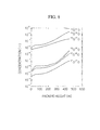
- the concentration distributions within each column in this conventional example are shown in FIG. 8.
- the packing height shown on the horizontal axis is defined so that the top of the first column 8 is set as a packing height of zero, and the packing heights of the subsequent columns are then added on, so that the bottom of the tenth column 34 corresponds with a packing height of 450 m.
- a portion of the vapor from the reboiler 36 of the tenth column 34 is produced via the pipeline 33 as the product (flow rate 0.0352 mol/s).
- 16 O 17 O is enriched from 0.074% to 2%
- 16 O 18 O is enriched from 0.407% to 25%.
- the recovery rates of 17 O and 18 O are 34.3% and 76.6% respectively.
- the production rate, when converted to water, amounts to 40 tones of 17 O water ( 17 O 1 atom%) per year, which represents an industrial scale production for the isotope.
- dephlegmators combined heat exchange and distillation apparatuses
- the main purpose of using these dephlegmators is to energy-saving and enable a more compact apparatus.
- Examples of energy-saving are disclosed in Unexamined Japanese Patent Application, First Publication No. Hei 8-66601 and Unexamined Japanese Patent Application, First Publication No. Hei 8-131704 (benzene-toluene, HiDiC).
- an example of a more compact apparatus is disclosed in Unexamined Japanese Patent Application, First Publication No. Hei 11-153383 (Method and device for producing nitrogen).
- an example targeting both energy-saving and a more compact apparatus is disclosed in U.S. Pat. No. 5,921,108 (Reflux condenser cryogenic rectification system for producing lower purity oxygen).
- the present invention takes the above factors into consideration, with an object of providing a separation and enrichment method and apparatus to minimize liquid holdup.
- the present inventors solve the problem of increasing liquid holdup within the distillation apparatus inherent in conventional technology by applying a dephlegmator to the conventional separation and enrichment method in which mixtures with a separation factor close to 1 are separated and enriched by distillation, and they thereby achieve a shortening of the start-up time.
- the present invention provides a separation and enrichment method which can reduce the operational costs and can markedly improve productivity.
- a separation and enrichment method of the present invention is a method of separating and enriching a mixture with a separation factor close to 1 using a distillation cascade, wherein a dephlegmation, in which distillation is conducted concurrently with heat exchange between the mixture and a heat-exchange-fluid, is conducted within at least one distillation section of the distillation cascade.
- Another separation and enrichment method of the present invention is a method of separating and enriching a mixture with a separation factor close to 1 using a distillation cascade, wherein at least one distillation section of the distillation cascade is divided into an upper and a lower portion at an arbitrary position, a bottom liquid of the upper portion flowing out from the bottom end of the upper portion is fed into the top end of a dephlegmation section, the bottom liquid is separated into a high volatile component and a low volatile component in the dephlegmation section, the high volatile component is fed into the bottom end of the upper portion as a vapor, and the low volatile component is fed into the top end of the lower portion as a liquid enriched component.
- another separation and enrichment method of the present invention is a method of separating and enriching a mixture with a separation factor close to 1 using a distillation cascade, wherein a bottom liquid of at least one distillation section of the distillation cascade is supplied to a dephlegmation section, and a dephlegmation, in which distillation of the mixture is conducted concurrently with heat exchange between the mixture and a heat-exchange-fluid, is conducted in the dephlegmation section.
- the quantity of heat applied to generate the ascending vapor required for ensuring adequate vapor-liquid contact is preferably the combined total of the quantity of heat applied to the dephlegmation section, and the quantity of heat applied to the reboiler attached to the distillation section.
- the entire quantity of heat that should be applied to generate the ascending vapor required in the dephlegmation section is preferably applied to the dephlegmation section.
- the heat exchange in the dephlegmation section can be performed by using at least two fluids of different pressure as the heating side fluid supplied to the heat exchange.
- the separation and enrichment method of the present invention can utilize heat-inleak as the heat source for applying to the dephlegmation section to achieve the necessary heat exchange.
- a separation and enrichment apparatus of the present invention is an apparatus for separating and enriching a mixture with a separation factor close to 1 using a distillation cascade, wherein at least one distillation column is a dephlegmator which conducts distillation concurrently with heat exchange between the mixture and a heat-exchange-fluid.
- Another separation and enrichment apparatus of the present invention is an apparatus for separating and enriching a mixture with a separation factor close to 1 using a distillation cascade, a dephlegmator which conducts distillation concurrently with heat exchange between the mixture and a heat-exchange-fluid is provided within at least one distillation column.
- a path can also be provided for enabling direct supply of the enriched component from a lower section of a distillation column to an upper section of the next distillation column in the distillation cascade.
- the aforementioned dephlegmator can utilize a construction in which the fluid passage through which the heat-exchange-fluid flows is divided into at least two sections in lengthwise along said passage.
- the aforementioned distillation column can utilize a construction comprising a reboiler passage for sending the bottom liquid from the distillation column to the reboiler, a shut-off valve provided in this passage, a reboiler bypass passage for supplying the bottom liquid to the next distillation column within the distillation cascade without passing through the reboiler, and a shut-off valve provided in this passage.
- FIG. 1 shows a first embodiment of a separation and enrichment apparatus of the present invention.
- This separation and enrichment apparatus represents an example in which a dephlegmator is used within one column of a plurality of columns which form a cascade.
- the first embodiment is basically the same system as the conventional example, and the same devices and pipelines are labeled with the same reference symbols, and description of those areas which are identical with the conventional example is omitted.
- the first embodiment is an example in which a dephlegmator is used in a Jth column 20 shown in FIG. 1.
- the dephlegmator 61 which is shown comprises a distillation passage 61a through which the mixture flows, and a fluid passage 61b through which a heat-exchange-fluid flows, and the mixture and the heat-exchange-fluid which flow through these passages 61a, 61b can undergo mutual heat exchange through the passage walls.
- the ascending vapor which flows out from the top of the column into a pipeline 15 is liquefied by a condenser 21, and then a portion of the liquid is returned to the Jth column 20 via a pipeline 51, and the remainder passes through a pipeline 16 and is returned to the (J-1)th column (the distillation column positioned immediately prior to the Jth column 20 in the plurality of columns which form the cascade).
- the condensate introduced into the Jth column from the pipeline 51 is distributed by a liquid distributor (not shown in the figure) provided inside the dephlegmator 61, and then flows down through the distillation passage 61a (including a pipeline), undergoes vapor liquid contact with the ascending vapor, while concurrently undergoing heat exchange with a heat-exchange-fluid such as medium pressure nitrogen and the surfaces of the passage wall, and partially vaporizes.
- a liquid distributor not shown in the figure
- the quantity of the bottom liquid has reduced, and the remaining liquid flows from the bottom of the Jth column 20, through the pipeline 17 and into a reboiler 22 where it vaporizes, and a portion of the vaporized vapor then passes through a pipeline 19 and is returned to the lower section of the Jth column 20 as the ascending vapor, and the remainder passes through a pipeline 18 and is fed into the upper section of (J+1)th column, which represents the next column in the cascade.
- a vapor is fed from the (J-1)th column through a pipeline 14 and into a position near the top of the Jth column 20.
- a liquid is fed from the (J+1)th column through a pipeline 25 and into the bottom of the Jth column 20.
- the medium pressure nitrogen vapor supplied to the dephlegmator 61 as the heat-exchange-fluid is introduced from a pipeline 23 into the fluid passage 61b in the upper section of the Jth column 20, and undergoes heat exchange with the bottom liquid (mixture) flowing down the distillation passage 61a via the passage walls, and as a result, condenses and passes out a pipeline 24 at the bottom of the Jth column 20 as a liquid.
- medium pressure nitrogen is also used as the heat-exchange-fluid in the condenser 21 and the reboiler 22, and nitrogen which passes through the pipeline 28 into the reboiler 22 and is liquefied, is fed out through a pipeline 29, and is then pumped, together with medium pressure liquid nitrogen from the pipeline 24, by a liquid pump (not shown in the figure) through a pipeline 26 and into the condenser 21.
- the liquid nitrogen vaporizes as a result of heat exchange with the ascending vapor of the Jth column 20, and passes out of the condenser 21 via a pipeline 27, where it is compressed by a compressor or the like (not shown in the figure), before being recycled and fed into either the medium pressure nitrogen vapor supply pipeline 23 of the Jth column 20, or the pipeline 28 leading to the reboiler 22.
- the compression method include methods using a low temperature compressor or methods in which the vapor is passed through a heat exchanger and heat is recovered and compression is performed at normal temperature.
- FIG. 2 A second embodiment of the present invention is shown in FIG. 2.
- the second embodiment is basically the same system as the first embodiment, and the same devices and pipelines are labeled with the same reference symbols, and description of those areas which are identical with the conventional example is omitted.
- the second embodiment uses a construction in which for a single arbitrary distillation column of the first embodiment, a dephlegmator is attached at an arbitrary position on the packed column.
- a partition S1 which divides the column into an upper and a lower sections is inserted in the middle of the Jth column 20, and the bottom liquid of an upper filled section 51 of the distillation column, positioned above the partition S I, passes out the bottom end through a pipeline 37 and enters the top end of a dephlegmator 41, where it is separated into a high volatile component and a low volatile component inside a distillation passage 41a.
- the high volatile component is then fed, via a pipeline 38, into the bottom of the upper filled section 51 of the distillation column as a vapor, and the low volatile component is fed, via a pipeline 39, into the top end of a lower filled section 52 of the distillation column, positioned below the partition S1, as a liquid enriched component.
- the ascending vapor in the lower filled section 52 of the distillation column passes through a pipeline 40 and enters the lower section of the dephlegmator 41. Furthermore, the ascending vapor in the lower filled section 52 of the distillation column can also be fed, as is, into the lower section of the upper filled section 51 of the distillation column.
- the heat-exchange-fluid supplied to the dephlegmator 41 is introduced in a vapor state from a pipeline 23 into a fluid passage 41b, and is then liquefied and passes out through a pipeline 24.
- This construction is identical with the first embodiment.
- FIG. 3 a third embodiment of the present invention is shown in FIG. 3.
- the third embodiment is basically the same system as the first embodiment, and the same devices and pipelines are labeled with the same reference symbols, and description of those areas which are identical with the conventional example is omitted.
- the third embodiment uses a construction in which for a single distillation column shown in the first embodiment, a packed column is provided in the upper section and a dephlegmator is provided in the lower section.
- a dephlegmator 44 is provided beneath the Jth column 20, and this dephlegmator 44 is connected to the bottom end of the Jth column 20 via pipelines 42 and 43.
- the bottom liquid of the packed section 53 of the distillation column passes out the bottom of the Jth column 20 via the pipeline 42, and then enters the top end of the dephlegmator 44 where it is separated into a high volatile component and a low volatile component inside a distillation passage 44a.
- the high volatile component is then fed, via a pipeline 43, into the bottom of the filled section 53 of the distillation column as a vapor, and the low volatile component passes from the bottom of the dephlegmator 44, through a pipeline 17 and into a reboiler 22.
- a portion of the vaporized and enriched component from the reboiler 22 passes through a pipeline 19, enters the lower section of the dephlegmator 44, and becomes an ascending vapor, and the remainder passes through a pipeline 18 and is fed into the next column within the cascade.
- the heat-exchange-fluid supplied to the dephlegmator 44 is introduced in a vapor state from a pipeline 23 into a fluid passage 44b, and is then liquefied and passes out through a pipeline 24.
- This construction is identical with the first embodiment.
- the total of the quantity of heat supplied to the dephlegmator 44 and the quantity of heat supplied to the reboiler 22 is a sufficient quantity of heat for generating the ascending vapor required in the distillation column 20. Furthermore, the quantity of heat-exchange-fluid introduced from the pipeline 23 may also be increased, so that the required reboil quantity for the distillation column 20 can be satisfied solely from the quantity of heat supplied to the dephlegmator 44. In such a case, the reboiler can be omitted.
- a separation and enrichment apparatus of the embodiment shown also comprises a reboiler passage 54 for sending the bottom liquid which has passed from the bottom of the dephlegmator 44 and through the pipeline 17, to the reboiler 22, a shut-off valve 46 provided in this passage 54, a reboiler bypass passage 45 for supplying the bottom liquid from the pipeline 17 to the next column without passing through the reboiler 22, and a shut-off valve 47 provided in this passage 45.
- the bottom liquid passes through the pipelines 45 and 48, and can be supplied directly to the next column without passing through the reboiler 22.
- the apparatus can be operated with a shortened start-up time.
- the switching operation for the shut-off valves 46, 47 can also be performed automatically.
- the boiler is provided.
- enriched liquid can be stored when operation of the apparatus is halted, and in addition, the reboiler can be used only during startup, to temporarily increase the reboil quantity, thereby enabling the start-up time to be shortened.
- FIG. 4 a fourth embodiment of the present invention is shown in FIG. 4.
- the fourth embodiment is basically the same system as the first embodiment, and the same devices and pipelines are labeled with the same reference symbols, and description of those areas which are identical with the conventional example is omitted.
- the fourth embodiment represents a further refinement of the first embodiment, wherein in the dephlegmator shown in FIG. 1, the fluid passage is divided into at least two sections from one end of the distillation passage through to the other end.
- a fluid passage 62 is divided into two sections by a partition S2, that is, an upper fluid passage 62c and a lower fluid passage 62d.
- heat-exchange-fluids can utilize, for example, medium pressure nitrogen vapor and high pressure nitrogen vapor.
- a medium pressure nitrogen vapor flows through the pipeline 23 as a heat-exchange-fluid and enters the upper fluid passage 62c from the upper section of the dephlegmator 62, and having been liquefied inside the upper fluid passage 62c, exits from the central section of the dephlegmator 62 via the pipeline 24.
- a high pressure nitrogen vapor flows through a pipeline 49 and enters the lower fluid passage 62d from the central section of the dephlegmator 62, and having been liquefied inside the lower fluid passage 62d, exits from the lower section of the dephlegmator 62 via a pipeline 50.
- the heat exchange temperature difference within the lower section of the Jth column 20 can be increased, enabling the quantity of partial vaporization within the lower section to be increased, and the height of the column to be decreased.
- Examples of methods for generating the high pressure nitrogen vapor include methods in which a separate compressor from the aforementioned compressor is prepared, and a portion of the medium pressure nitrogen vapor is further compressed, or methods in which the aforementioned compressor is capable of internal multistage compression, in which case the medium pressure nitrogen vapor is output from partway along the compressor, and the high pressure nitrogen vapor is output from the final stage.
- FIG. 5 shows a system which uses plate fins for performing the vapor liquid contact within the separation and enrichment apparatus shown in FIG. 1.
- the passages which make up the plate fin type heat exchanger function as the aforementioned distillation passages and fluid passages, and these passages are aligned alternately, forming a dephlegmator.
- a liquid or vapor mixture is supplied through pipelines 14, 51, 19 and 25, and distillation proceeds within a distillation passage 63a shown in FIG. 5A, and the liquid mixture passes out through the pipeline 17 and the vapor mixture passes out through the pipeline 15.
- FIG. 6 shows a system which uses plate fins for performing the vapor liquid contact within the separation and enrichment apparatus shown in FIG. 4, wherein the heat exchange passage is divided into an upper section and a lower sections of the dephlegmator.
- a fluid passage 64b is divided into two sections, that is, an upper fluid passage 64c and a lower fluid passage 64d.
- a liquid or vapor mixture is supplied through pipelines 14, 51, 19 and 25, and distillation proceeds within a distillation passage 64a shown in FIG. 6A, and the liquid mixture passes out through the pipeline 17 and the vapor mixture passes out through the pipeline 15.
- a method could be adopted wherein a medium pressure nitrogen vapor is introduced into the upper fluid passage 64c through the pipeline 23 and exits through the passage 24, while a high pressure nitrogen vapor is introduced into the lower fluid passage 64d through the pipeline 49 and exits through the passage 50.
- This number of fluids is not restricted to two fluids, and naturally the process could also be performed using 3 or more fluids.
- Table 4 and Table 5 show the totals for the quantity of liquid holdup (during normal operation) for 16 O 17 O and 16 O 18 O, which represent the target components within the distillation column.
- Holdup represents the quantity of liquid holdup when a conventional plate fin type reboiler is used
- (2) Holdup represents the quantity of liquid holdup in the case of the present invention, using a dephlegmator and omitting the reboiler
- (3) Holdup represents the quantity of holdup in another case of the present invention, using a dephlegmator and reducing the quantity of liquid holdup within the reboiler to 1/5th of the conventional quantity.
- the calculation of each of these liquid holdup quantities assumed that the quantity of liquid holdup within the vapor liquid contact section was the same for each of (1) to (3) above. (This is an acceptable assumption for displaying the effects of the present invention.)
- t p I( X -Z F ) P(Y p -Z F ) + t w
- t p is a time [s] from the commencement of an operation until the flow of a production rate reaches a fixed value
- t w is a time [s] from the commencement of an operation until the flow of an exhaust vapor rate reaches a fixed value
- I is a total holdup quantity [mol]
- P is a production rate [mol/s]
- x is an average molar fraction [-] of a target component
- y p is a molar fraction [-] of a target component in the product
- z F is a molar fraction [-] of a target component in the feed
- thermo siphon based plate fin type heat exchanger Normally, in order to ensure stable operation, the aforementioned type of thermo siphon based plate fin type heat exchanger must be at least half immersed in the liquid, and it became evident that the quantity of holdup of the vapor liquid 2 phase stream within the heat exchanger needed to be considered in addition to that external to the heat exchanger.
- a dephlegmator need not necessarily be used for all of the reboilers, and even if the method of the present invention is applied only to those column for which the quantity of liquid holdup of the target components is large, the start-up time can still be shortened effectively, and the cost of the apparatus can also be minimized.
- the quantity of liquid holdup within the distillation column can be reduced.
- distillation in the distillation section can be enhanced, while the quantity of exchanged heat of the reboiler can be reduced.
- the reboiler can be either omitted or scaled down, and the quantity of liquid holdup can be reduced markedly.
Landscapes
- Chemical & Material Sciences (AREA)
- Chemical Kinetics & Catalysis (AREA)
- Engineering & Computer Science (AREA)
- Physics & Mathematics (AREA)
- Mechanical Engineering (AREA)
- Thermal Sciences (AREA)
- General Engineering & Computer Science (AREA)
- Vaporization, Distillation, Condensation, Sublimation, And Cold Traps (AREA)
- Separation By Low-Temperature Treatments (AREA)
- Organic Low-Molecular-Weight Compounds And Preparation Thereof (AREA)
Abstract
Description
| Element | Abundance ratio |
| 16O | 0.99759 |
| 17O | 0.00037 |
| 18O | 0.00204 |
| Total | 1.00000 |
| Mass number | Oxygen molecule | Abundance ratio |
| 32 | 16O16O | 0.99519 |
| 33 | 16O17O | 0.00074 |
| 34 | 16O18O | 0.00407 |
| 34 | 17O17O | 1.37E-07 |
| 35 | 17O18O | 1.51E-06 |
| 36 | 18O18O | 4.16E-06 |
| Total | 1.00000 |


tp is a time [s] from the commencement of an operation until the flow of a production rate reaches a fixed value,
tw is a time [s] from the commencement of an operation until the flow of an exhaust vapor rate reaches a fixed value,
I is a total holdup quantity [mol],
P is a production rate [mol/s],
yp is a molar fraction [-] of a target component in the product,
zF is a molar fraction [-] of a target component in the feed
Claims (12)
- A method of separating and enriching a mixture with a separation factor close to 1 using a distillation cascade, wherein a dephlegmation, in which distillation is conducted concurrently with heat exchange between the mixture and a heat-exchange-fluid, is conducted within at least one distillation section of the distillation cascade.
- A method of separating and enriching a mixture with a separation factor close to 1 using a distillation cascade, wherein at least one distillation section of the distillation cascade is divided into an upper and a lower portion at an arbitrary position, a bottom liquid of the upper portion flowing out from the bottom end of the upper portion is fed into the top end of a dephlegmation section, the bottom liquid is separated into a high volatile component and a low volatile component in the dephlegmation section, the high volatile component is fed into the bottom end of the upper portion as a vapor, and the low volatile component is fed into the top end of the lower portion as a liquid enriched component.
- A method of separating and enriching a mixture with a separation factor close to 1 using a distillation cascade, wherein a bottom liquid of at least one distillation section of the distillation cascade is supplied to a dephlegmation section, and a dephlegmation, in which distillation of the mixture is conducted concurrently with heat exchange between the mixture and a heat-exchange-fluid, is conducted in the dephlegmation section.
- A method of separating and enriching a mixture according to either one of claim 2 and claim 3, wherein in said dephlegmation section, a quantity of heat applied to generate an ascending vapor required for ensuring adequate vapor-liquid contact is the sum of a quantity of heat applied to said dephlegmation section, and a quantity of heat applied to a reboiler attached to said distillation section.
- A method of separating and enriching a mixture according to either one of claim 2 and claim 3, wherein an entire quantity of heat that is applied to generate an ascending vapor required in said dephlegmation section is applied to said dephlegmation section.
- A method of separating and enriching a mixture according to either one of claim 2 and claim 3, wherein heat exchange in said dephlegmation section is performed by using at least two fluids of different pressure as a heating side fluid supplied to said heat exchange.
- A method of separating and enriching a mixture according to either one of claim 2 and claim 3, wherein heat-inleak is used as a heat source for applying to said dephlegmation section for heat exchange.
- An apparatus for separating and enriching a mixture with a separation factor close to 1 using a distillation cascade, wherein at least one distillation column is a dephlegmator which conducts distillation concurrently with heat exchange between said mixture and a heat-exchange-fluid.
- An apparatus for separating and enriching a mixture with a separation factor close to 1 using a distillation cascade, wherein a dephlegmator which conducts distillation concurrently with heat exchange between said mixture and a heat-exchange-fluid is provided within at least one distillation column.
- An apparatus for separating and enriching a mixture according to either one of claim 8 and claim 9, wherein a path is provided for supplying an enriched component from a lower section of said distillation column directly to an upper section of a next distillation column.
- An apparatus for separating and enriching a mixture according to either one of claim 8 and claim 9, wherein in said dephlegmator, a fluid passage through which a heat-exchange-fluid flows is divided into at least two sections in lengthwise along said passage.
- An apparatus for separating and enriching a mixture according to either one of claim 8 and claim 9, wherein said distillation column comprises; a reboiler passage for sending a bottom liquid from said distillation column to a reboiler, a shut-off valve provided in said passage, a reboiler bypass passage for supplying said bottom liquid to a next distillation column without passing through said reboiler, and a shut-off valve provided in said passage.
Applications Claiming Priority (3)
| Application Number | Priority Date | Filing Date | Title |
|---|---|---|---|
| JP2000356663A JP3505503B2 (en) | 2000-11-22 | 2000-11-22 | Method and apparatus for separating and concentrating a mixture having a separation coefficient close to 1 by distillation |
| JP2000356663 | 2000-11-22 | ||
| PCT/JP2001/010203 WO2002041977A1 (en) | 2000-11-22 | 2001-11-22 | Method and device for separation and concentration by evaporation of mixture with separation factor of approx. 1 |
Publications (3)
| Publication Number | Publication Date |
|---|---|
| EP1338327A1 true EP1338327A1 (en) | 2003-08-27 |
| EP1338327A4 EP1338327A4 (en) | 2005-04-27 |
| EP1338327B1 EP1338327B1 (en) | 2008-07-09 |
Family
ID=18828862
Family Applications (1)
| Application Number | Title | Priority Date | Filing Date |
|---|---|---|---|
| EP01997341A Expired - Lifetime EP1338327B1 (en) | 2000-11-22 | 2001-11-22 | Method and device for separation and concentration by evaporation of mixture with separation factor of approx. 1 |
Country Status (5)
| Country | Link |
|---|---|
| US (1) | US7297237B2 (en) |
| EP (1) | EP1338327B1 (en) |
| JP (1) | JP3505503B2 (en) |
| DE (1) | DE60134770D1 (en) |
| WO (1) | WO2002041977A1 (en) |
Cited By (2)
| Publication number | Priority date | Publication date | Assignee | Title |
|---|---|---|---|---|
| EP2499224A4 (en) * | 2009-11-09 | 2014-05-07 | Rohit Joshi | Method and apparatus for processing of spent lubricating oil |
| EP2837904A4 (en) * | 2012-03-27 | 2016-03-30 | Taiyo Nippon Sanso Corp | DISTILLATION DEVICE |
Families Citing this family (16)
| Publication number | Priority date | Publication date | Assignee | Title |
|---|---|---|---|---|
| EP1604729B1 (en) * | 2003-03-04 | 2011-10-05 | Taiyo Nippon Sanso Corporation | Method for concentrating oxygen isotope |
| JP4699784B2 (en) * | 2005-03-28 | 2011-06-15 | 大陽日酸株式会社 | Method and apparatus for concentrating oxygen isotopes |
| US20070029077A1 (en) * | 2005-08-02 | 2007-02-08 | Mirolli Mark D | Hybrid heat exchanger |
| MX2009003855A (en) * | 2006-10-10 | 2009-10-13 | Texas A & M Univ Sys | Desalination system. |
| JP5026774B2 (en) * | 2006-11-28 | 2012-09-19 | 大陽日酸株式会社 | Distillation equipment |
| US7687674B2 (en) | 2006-12-28 | 2010-03-30 | Uop Llc | Low temperature process for recovering and producing para-xylene and heat exchange network therefore |
| US8562932B2 (en) * | 2009-08-21 | 2013-10-22 | Silicor Materials Inc. | Method of purifying silicon utilizing cascading process |
| KR101172422B1 (en) * | 2009-12-11 | 2012-08-08 | 에스케이씨 주식회사 | Waste Heat Recovery System |
| US8758572B2 (en) * | 2011-04-20 | 2014-06-24 | Exelon Generation Company, Llc | Method for the separation and concentration of isotopologues |
| WO2013111023A1 (en) * | 2012-01-25 | 2013-08-01 | Amit Katyal | A novel horizontal method for tray distillation and other gas-liquid contact operations |
| US9168467B1 (en) | 2012-03-20 | 2015-10-27 | Vitaly Leonidovich Bondarenko | Assembly for separating gas mixtures in fractionating columns |
| CN108514753A (en) * | 2018-05-16 | 2018-09-11 | 马鞍山纽盟知识产权管理服务有限公司 | A kind of rectifier unit |
| RU2730289C2 (en) * | 2018-12-24 | 2020-08-21 | Андрей Владиславович Курочкин | Low-temperature dephlegmation unit with rectification ltdr for complex gas treatment and production of lng |
| RU2705160C1 (en) * | 2018-12-24 | 2019-11-05 | Андрей Владиславович Курочкин | Unit of low-temperature dephlegmation with rectification ltdr for complex gas treatment with generation of lng |
| JP6913786B1 (en) | 2020-03-31 | 2021-08-04 | 大陽日酸株式会社 | Stable isotope enrichment method |
| JP7808301B2 (en) * | 2021-01-05 | 2026-01-29 | 国立大学法人信州大学 | Oxygen isotope separation method |
Family Cites Families (28)
| Publication number | Priority date | Publication date | Assignee | Title |
|---|---|---|---|---|
| US217703A (en) * | 1879-07-22 | Improvement in stills | ||
| US1530325A (en) * | 1922-08-11 | 1925-03-17 | Griscom Russell Co | Oil dephlegmator |
| US1507108A (en) * | 1923-09-21 | 1924-09-02 | James F Cyphers | Process and apparatus for the continuous distillation of alcohol |
| US1619909A (en) | 1925-10-15 | 1927-03-08 | Air Reduction | Separation of the constituents of ternary gaseous mixtures |
| US2787526A (en) * | 1943-11-09 | 1957-04-02 | Jerome S Spevack | Method of isotope concentration |
| US2895803A (en) * | 1950-09-29 | 1959-07-21 | Jerome S Spevack | Isotope concentration system |
| CH486315A (en) * | 1968-02-27 | 1970-02-28 | Laszlo Dr Futo | Method for the production of pellets, in particular from wood, and device for carrying out the method |
| FR2298361A1 (en) * | 1973-02-27 | 1976-08-20 | Pierre Delvalle | CHEMICAL SEPARATION PROCESS |
| US3969450A (en) | 1973-11-14 | 1976-07-13 | Standard Oil Company | Heat-exchanger trays and system using same |
| SE7813257L (en) * | 1978-01-04 | 1979-07-05 | Markfort Dieter | KIT AND DEVICE FOR RECTIFICATION |
| DE2920436A1 (en) * | 1979-05-19 | 1980-12-04 | Bayer Ag | METHOD FOR PRODUCING EPSILON-CAPROLACTON |
| US4315902A (en) * | 1980-02-07 | 1982-02-16 | Phillips Petroleum Company | Method for producing carbon black |
| US4315802A (en) | 1980-05-12 | 1982-02-16 | The Lummus Company | Process and apparatus for fractionating close boiling components of a multi-component system |
| JPS5864101A (en) | 1981-10-13 | 1983-04-16 | ザ・ル−マス・コンパニ− | Fractionation method and apparatus |
| US4533375A (en) * | 1983-08-12 | 1985-08-06 | Erickson Donald C | Cryogenic air separation with cold argon recycle |
| EP0230249A3 (en) * | 1986-01-16 | 1988-08-17 | Peter Dr.-Ing. Vinz | Energy saving circuit for continuous-operation distillation apparatuses |
| GB2208699B (en) * | 1988-08-18 | 1992-07-08 | Costain Eng Ltd | Separation of nitrogen from methane-containing gas streams |
| JPH0263501A (en) * | 1988-08-29 | 1990-03-02 | Toshiba Corp | Temperature controller for distillation tower |
| US5011521A (en) * | 1990-01-25 | 1991-04-30 | Air Products And Chemicals, Inc. | Low pressure stripping process for production of crude helium |
| US5051120A (en) * | 1990-06-12 | 1991-09-24 | Union Carbide Industrial Gases Technology Corporation | Feed processing for nitrogen rejection unit |
| US5230217A (en) | 1992-05-19 | 1993-07-27 | Air Products And Chemicals, Inc. | Inter-column heat integration for multi-column distillation system |
| US5419887A (en) * | 1994-01-25 | 1995-05-30 | Research & Development Institute, Inc. | Separation of the isotopes of boron by chemical exchange reactions |
| DE69529146T2 (en) | 1994-08-29 | 2003-11-13 | Kansai Chemical Engineering Co., Ltd. | DISTILLATION COLUMN WITH INTERNAL HEAT EXCHANGE |
| US5626034A (en) * | 1995-11-17 | 1997-05-06 | Manley; David | Mixed refrigerants in ethylene recovery |
| US6336344B1 (en) * | 1999-05-26 | 2002-01-08 | Chart, Inc. | Dephlegmator process with liquid additive |
| JP4495279B2 (en) * | 1999-10-12 | 2010-06-30 | 大陽日酸株式会社 | Distillation apparatus, oxygen isotope weight component concentration method, and heavy oxygen water production method |
| JP2001239101A (en) * | 2000-03-01 | 2001-09-04 | Nippon Sanso Corp | Distillation separation method and distillation apparatus for a mixture having a separation coefficient close to 1 |
| US6899743B2 (en) * | 2002-06-12 | 2005-05-31 | Membrane Technology And Research, Inc. | Separation of organic mixtures using gas separation or pervaporation and dephlegmation |
-
2000
- 2000-11-22 JP JP2000356663A patent/JP3505503B2/en not_active Expired - Lifetime
-
2001
- 2001-11-22 WO PCT/JP2001/010203 patent/WO2002041977A1/en not_active Ceased
- 2001-11-22 EP EP01997341A patent/EP1338327B1/en not_active Expired - Lifetime
- 2001-11-22 US US10/432,164 patent/US7297237B2/en not_active Expired - Fee Related
- 2001-11-22 DE DE60134770T patent/DE60134770D1/en not_active Expired - Lifetime
Cited By (2)
| Publication number | Priority date | Publication date | Assignee | Title |
|---|---|---|---|---|
| EP2499224A4 (en) * | 2009-11-09 | 2014-05-07 | Rohit Joshi | Method and apparatus for processing of spent lubricating oil |
| EP2837904A4 (en) * | 2012-03-27 | 2016-03-30 | Taiyo Nippon Sanso Corp | DISTILLATION DEVICE |
Also Published As
| Publication number | Publication date |
|---|---|
| EP1338327B1 (en) | 2008-07-09 |
| DE60134770D1 (en) | 2008-08-21 |
| JP3505503B2 (en) | 2004-03-08 |
| EP1338327A4 (en) | 2005-04-27 |
| WO2002041977A1 (en) | 2002-05-30 |
| JP2002159830A (en) | 2002-06-04 |
| US7297237B2 (en) | 2007-11-20 |
| US20040060810A1 (en) | 2004-04-01 |
Similar Documents
| Publication | Publication Date | Title |
|---|---|---|
| EP1338327B1 (en) | Method and device for separation and concentration by evaporation of mixture with separation factor of approx. 1 | |
| EP0501471B1 (en) | Boiling process and a heat exchanger for use in the process | |
| JP4495279B2 (en) | Distillation apparatus, oxygen isotope weight component concentration method, and heavy oxygen water production method | |
| US6321565B1 (en) | Method and apparatus for the production of heavy oxygen water | |
| TW542895B (en) | Obtaining argon using a three-column system for the fractionation of air and a crude argon column | |
| NO169197B (en) | PROCEDURE FOR SEPARATION OF ARGON / OXYGEN MIXTURES BY CRYOGEN DISTILLATION | |
| US20120085126A1 (en) | Low energy distillation system and method | |
| US7249469B2 (en) | Method for separating a multicomponent stream | |
| JP5132822B1 (en) | Distillation equipment | |
| CA2574113A1 (en) | Distillation process using microchannel technology | |
| US7828939B2 (en) | Method for concentrating heavy nitrogen isotope | |
| US20080121512A1 (en) | Distillation apparatus | |
| EP2896442A1 (en) | Distillation column divided in several parts comprising a mechanical heat pump | |
| SK282908B6 (en) | A method of cryogenic separation of a mixture of atmospheric gases | |
| US9168467B1 (en) | Assembly for separating gas mixtures in fractionating columns | |
| TW422732B (en) | Method of and apparatus for air separation | |
| JP2009030966A (en) | Method and device for producing argon by low-temperature air separation | |
| MXPA02007813A (en) | Multiple process plant product lines from a common set of engineered components. | |
| EP0908226A2 (en) | Process and apparatus for separation of stable isotope compound | |
| US4755202A (en) | Process and apparatus to produce ultra high purity oxygen from a gaseous feed | |
| US6761213B2 (en) | Reboiler/condenser heat exchanger of the bath type | |
| JPH07218122A (en) | Method and apparatus for separating air | |
| CN114087848A (en) | Method and apparatus for separating 13C16O from natural CO | |
| JP2001239101A (en) | Distillation separation method and distillation apparatus for a mixture having a separation coefficient close to 1 | |
| JP2001165564A (en) | Low-temperature air separation method and device |
Legal Events
| Date | Code | Title | Description |
|---|---|---|---|
| PUAI | Public reference made under article 153(3) epc to a published international application that has entered the european phase |
Free format text: ORIGINAL CODE: 0009012 |
|
| 17P | Request for examination filed |
Effective date: 20030520 |
|
| AK | Designated contracting states |
Designated state(s): AT BE CH CY DE DK ES FI FR GB GR IE IT LI LU MC NL PT SE TR |
|
| RIN1 | Information on inventor provided before grant (corrected) |
Inventor name: ASANO, KOUICHI Inventor name: KAWAKAMI, HIROSHI,C/O NIPPON SANSO CORPORATION Inventor name: EGOSHI, NOBUAKI,C/O NIPPON SANSO CORPORATION Inventor name: HAYASHIDA, SHIGERU,C/O NIPPON SANSO CORPORATION |
|
| RIN1 | Information on inventor provided before grant (corrected) |
Inventor name: HAYASHIDA, SHIGERU,C/O NIPPON SANSO CORPORATION Inventor name: EGOSHI, NOBUAKI,C/O NIPPON SANSO CORPORATION Inventor name: ASANO, KOICHI Inventor name: KAWAKAMI, HIROSHI,C/O NIPPON SANSO CORPORATION |
|
| RIN1 | Information on inventor provided before grant (corrected) |
Inventor name: HAYASHIDA, SHIGERU,C/O NIPPON SANSO CORPORATION Inventor name: KAWAKAMI, HIROSHI,C/O NIPPON SANSO CORPORATION Inventor name: EGOSHI, NOBUAKI,C/O NIPPON SANSO CORPORATION Inventor name: ASANO, KOICHI |
|
| RBV | Designated contracting states (corrected) |
Designated state(s): AT BE CH DE FR GB LI |
|
| A4 | Supplementary search report drawn up and despatched |
Effective date: 20050310 |
|
| RAP1 | Party data changed (applicant data changed or rights of an application transferred) |
Owner name: ASANO, KOICHI Owner name: TAIYO NIPPON SANSO CORPORATION |
|
| RIN1 | Information on inventor provided before grant (corrected) |
Inventor name: EGOSHI, NOBUAKI,C/O TAIYO NIPPON SANSO CORP. Inventor name: KAWAKAMI, HIROSHI,C/O TAIYO NIPPON SANSO CORP. Inventor name: ASANO, KOICHI Inventor name: HAYASHIDA, SHIGERU,C/O TAIYO NIPPON SANSO CORP. |
|
| 17Q | First examination report despatched |
Effective date: 20051109 |
|
| GRAP | Despatch of communication of intention to grant a patent |
Free format text: ORIGINAL CODE: EPIDOSNIGR1 |
|
| RBV | Designated contracting states (corrected) |
Designated state(s): DE FR GB |
|
| GRAS | Grant fee paid |
Free format text: ORIGINAL CODE: EPIDOSNIGR3 |
|
| GRAA | (expected) grant |
Free format text: ORIGINAL CODE: 0009210 |
|
| AK | Designated contracting states |
Kind code of ref document: B1 Designated state(s): DE FR GB |
|
| REG | Reference to a national code |
Ref country code: GB Ref legal event code: FG4D |
|
| REF | Corresponds to: |
Ref document number: 60134770 Country of ref document: DE Date of ref document: 20080821 Kind code of ref document: P |
|
| PLBE | No opposition filed within time limit |
Free format text: ORIGINAL CODE: 0009261 |
|
| STAA | Information on the status of an ep patent application or granted ep patent |
Free format text: STATUS: NO OPPOSITION FILED WITHIN TIME LIMIT |
|
| 26N | No opposition filed |
Effective date: 20090414 |
|
| PGFP | Annual fee paid to national office [announced via postgrant information from national office to epo] |
Ref country code: DE Payment date: 20141119 Year of fee payment: 14 Ref country code: GB Payment date: 20141119 Year of fee payment: 14 Ref country code: FR Payment date: 20141119 Year of fee payment: 14 |
|
| REG | Reference to a national code |
Ref country code: DE Ref legal event code: R119 Ref document number: 60134770 Country of ref document: DE |
|
| GBPC | Gb: european patent ceased through non-payment of renewal fee |
Effective date: 20151122 |
|
| REG | Reference to a national code |
Ref country code: FR Ref legal event code: ST Effective date: 20160729 |
|
| PG25 | Lapsed in a contracting state [announced via postgrant information from national office to epo] |
Ref country code: DE Free format text: LAPSE BECAUSE OF NON-PAYMENT OF DUE FEES Effective date: 20160601 Ref country code: GB Free format text: LAPSE BECAUSE OF NON-PAYMENT OF DUE FEES Effective date: 20151122 |
|
| PG25 | Lapsed in a contracting state [announced via postgrant information from national office to epo] |
Ref country code: FR Free format text: LAPSE BECAUSE OF NON-PAYMENT OF DUE FEES Effective date: 20151130 |