EP1337020A2 - Electric connection box for automobile - Google Patents
Electric connection box for automobile Download PDFInfo
- Publication number
- EP1337020A2 EP1337020A2 EP03002587A EP03002587A EP1337020A2 EP 1337020 A2 EP1337020 A2 EP 1337020A2 EP 03002587 A EP03002587 A EP 03002587A EP 03002587 A EP03002587 A EP 03002587A EP 1337020 A2 EP1337020 A2 EP 1337020A2
- Authority
- EP
- European Patent Office
- Prior art keywords
- cover
- connection box
- main body
- electrical connection
- movable cover
- Prior art date
- Legal status (The legal status is an assumption and is not a legal conclusion. Google has not performed a legal analysis and makes no representation as to the accuracy of the status listed.)
- Granted
Links
Images



Classifications
-
- H—ELECTRICITY
- H02—GENERATION; CONVERSION OR DISTRIBUTION OF ELECTRIC POWER
- H02G—INSTALLATION OF ELECTRIC CABLES OR LINES, OR OF COMBINED OPTICAL AND ELECTRIC CABLES OR LINES
- H02G3/00—Installations of electric cables or lines or protective tubing therefor in or on buildings, equivalent structures or vehicles
- H02G3/02—Details
- H02G3/08—Distribution boxes; Connection or junction boxes
- H02G3/16—Distribution boxes; Connection or junction boxes structurally associated with support for line-connecting terminals within the box
-
- H—ELECTRICITY
- H02—GENERATION; CONVERSION OR DISTRIBUTION OF ELECTRIC POWER
- H02G—INSTALLATION OF ELECTRIC CABLES OR LINES, OR OF COMBINED OPTICAL AND ELECTRIC CABLES OR LINES
- H02G3/00—Installations of electric cables or lines or protective tubing therefor in or on buildings, equivalent structures or vehicles
- H02G3/02—Details
- H02G3/08—Distribution boxes; Connection or junction boxes
- H02G3/081—Bases, casings or covers
Definitions
- the present invention relates to an electric connection box for an automobile such as a junction box, a relay box or a fusible link box, and more specifically relates to a compact electric connection box that occupies as little space in the automobile as possible.
- a conventional electric connection box for an automobile is provided with an openable cover on a top surface thereof. When performing maintenance, the cover is opened so that electrical components housed in the connection box can be accessed.
- the conventional electric connection box is typically placed at a side inner surface of an engine room of the automobile in a state where the cover is easily accessed.
- a related art of the conventional electric connection box is disclosed in Japanese Patent Application Laid Open H11-18246.
- a way of eliminating redundant space is to dispose the electrical connection box in an unutilized dead space, for example, a space between a headlight and a wheel arch.
- the present invention is focused on solving the above problem and is intended to increase flexibility of location in the engine room as well as to enable easy maintenance.
- An electrical connection box is provided with a movable cover, a fixed cover and a main body housed in the movable cover and the fixed cover.
- the main body is provided with a maintenance face for attachment of a wiring and an electrical component and the movable cover is detachably attached thereto.
- the movable cover covers the main body so that the maintenance face thereof is exposed.
- the movable cover is detachably attached to the fixed cover and the fixed cover covers the maintenance face.
- the movable cover of the electrical connection box is further provided with a side cover detachably attached to the movable cover so as to cover side surfaces of the main body.
- an outer surface of the movable cover faces upward and the maintenance face faces downward when the movable cover is attached to the fixed cover.
- the electrical connection box is further provided with a means for sliding the movable cover and the fixed cover so that the movable cover slides sideways into the fixed cover so as to be attached.
- the electrical connection box is further provided with a means for engagement of the movable cover and the fixed cover, which is provided with a claw for canceling the engagement, and the movable cover is further provided with a projection for a slide operation thereof.
- the claw and the projection can be simultaneously operational.
- inside of the movable cover and the fixed cover is substantially sealed when the movable cover is attached to the fixed cover.
- the maintenance face is easily exposed when the movable body is detached from the fixed body and is rotated upside down so that the maintenance procedure can be easily achieved.
- the movable body can be slid sideways into the fixed body so that the maintenance procedure can be achieved if the electrical connection box is installed where a top surface thereof is covered.
- the electrical connection box provides a flexibility of location thereof as well as ease of maintenance.
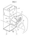
- An electrical connection box 10 is disposed between a headlight 14 and a wheel arch 15 in a vicinity of a battery 13 held on a mount table 12 in an engine room of an automobile body as shown in Fig. 1.
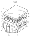
- the electrical connection box 10 is composed of a main body made of resin housing electrical circuits and a cover 17 housing the main body in an installation state as shown in Fig. 2.
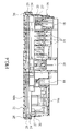
- the main body 16 has a flat rectangular cuboid shape as shown in Figs. 2-4.
- One of the surfaces of the main body 16 is a maintenance face 16a for performing maintenance on the electrical circuit, which is opposite to a surface facing an upper cover 21 described below and is drawn to be downward in Fig. 2.
- the maintenance face 16a is provided with connector connection portions 18 for connection with connectors (not shown) of terminal portions of a wiring harness W and electrical components installation portions 19 for installing electrical components 19 such as a relay and a fuse (not shown) thereto.
- Side surfaces perpendicular to the maintenance face 16a are provided with engagement projections 20 for engaging with the upper cover 21.
- the cover 17 is composed of the upper cover 21 which is movable, a side cover 22 and an lower cover 23 which is fixed to the engine room.
- the upper cover 21 is made of a relatively soft material, polypropylene (PP), and has a rectangular plate shape which is slightly larger than an opposite face 16b opposite to the maintenance face 16a of the main body 16.
- a peripheral edge of the rectangular plate is provided with an inner hanging wall 24 and an outer hanging wall 25 projecting downward.
- An engaging groove 26 is formed between the inner hanging wall 24 and the outer hanging wall 25.
- Engagement holes 27 are formed on the inner hanging wall 24 corresponding to the engagement projections 20 so as to engage therewith.
- the main body 16 is engaged with the upper cover 21 in a state where the opposite face 16b faces to the upper cover 21 thereby the upper cover 21 covers a whole upper surface of the main body 16. Further, latch projections 28 are projected from the outer hanging wall 25 as shown in Figs. 5 and 6 so that the upper cover 21 can be engaged with the side cover 22.
- the side cover 22 is made of a relatively soft material, polypropylene (PP), and is provided with a rectangular frame portion 22a plate shape which is slightly larger than the maintenance face 16a of the main body 16 and a side lid portion 22b integral with and hanging downward from the frame portion 22a.
- An outer surface of the rectangular frame portion 22a is provided with resilient latch arms 30 extending upward corresponding to the latch projections 28.
- Each of the resilient latch arms 30 is provided with a latch hole 31 at a proximal side thereof.
- a distal end of each of the resilient latch arms 30 can elastically deform outward and an inner side thereof is provided with a clicker projection 32 projecting inward.
- the main body 16 is inserted into the side cover 22 and the latch projections 28 of the upper cover 21 are respectively engaged with the latch holes 31 of the resilient latch arms 30 so that the upper cover 21 is installed to the side cover 22. Thereby the main body 16 is covered by the frame portion 22a.
- the resilient latch arms 30 are respectively provided with arm guard walls 33 surrounding thereto so that the resilient latch arms 30 are prevented from over-deforming.
- the frame portion 22a is provided with a pair of side rails 34 projecting therefrom, running on both sides thereof and substantially vertical to the side lid portion 22b, each of which is composed of three short divided portions.
- the side cover 22 can be slid into the lower cover 23 by means of the side rails 34 so that the side cover 22 is detachably attached to the lower cover 23.
- the side lid portion 22b is integrally provided with a pair of collar portions 35 and a pair of locking projections 36 at both ends thereof.
- the lower cover 23 has a box-like shape. An upper surface, which faces to the headlight 14, and a side surface, which faces to the battery 13, of the lower cover 23 are opened so as to receive the upper cover 21 and the main body 16. A bottom surface 23a thereof is spherically shaped so as not to interfere with the wheel arch 15.
- the lower cover 23 is fixed to an inner surface of the engine room 11 by means of plural bracket portions 37 as shown in Fig. 2.
- Both side wall portions 23b of the lower cover 23 are respectively provided with a pair of lower side rails 38 projecting inward and running in a substantially horizontal level on the inner surfaces thereof.
- Guide faces 39 for guiding insertion of the side rails 34 of the side cover 22 are respectively provided in the vicinity of ends of the lower side rails 38.
- the side rails 34 are guided by the guide faces 39 so as to be slid into the lower side rails 38, thereby the upper cover 21 and the side cover 22 are moved into the lower cover 23 at an installation position.
- Adversely, the upper cover 21 and the side cover 22 can be slid out from the lower cover 23 by sliding the side rails 34 on the lower side rails 38.
- the upper cover 21 and the side cover 22 can be detachably attached to the lower cover 23 by means of the side rails 34 and the lower side rails 38. Furthermore, at the installation position, the opened surfaces of the lower cover 23 is covered with the upper cover 21 and the side cover 22 so that the main body 16 is housed so as to be substantially sealed in the cover 17.
- the pair of side wall portions 23b of the lower cover 23 are respectively provided with resilient locking projections 40 in a vicinity of the opened surfaces thereof, with which the locking projections 36 of the side cover 22 are respectively engaged so that the side cover 22 is detachably fixed to the lower cover 23 at a covering position.
- a harness insertion hole 41 is formed on one of the side wall portions 23b of the lower cover 23 so that the wiring harness W can be conducted into the lower cover 23. Connectors (not shown) of the wiring harness W are connected to the connector connection portions 18 of the main body 16.
- the main body 16 is disposed inside the upper cover 21 as the maintenance face 16a thereof faces downward.
- the main body 16 is inserted to the inner hanging wall 24 of the upper cover 21 so that the engagement projections 20 of the main body 16 are respectively engaged with the engagement holes 27 of the upper cover 21 and the main body 16 is fixed to the upper cover 21.
- the side cover 22 is inserted below the upper cover 21 to which the main body 16 is fixed and an upper end of the frame portion 22a is inserted into the engaging groove 26 of the upper cover 21.
- the tip ends of the resilient latch arms 30 of the side cover 22 respectively abut the latch projections 28 of the upper cover 21 so as to elastically deform outward and allow an insertion of the side cover 22.
- the resilient latch arms 30 are further inserted so that the latch holes 31 thereof match the latch projections 28 as shown in Fig. 6(a)
- the resilient latch arms 30 elastically deform to restore to the original position so that the latchholes 31 of the resilient latch arms 30 are respectively engaged with the latch projections 28.
- the side cover 22 is fixed to the upper cover 21.
- the lower cover 23 is fixed to a predetermined position in the engine room 11 via the respective bracket 37.
- the wiring harness W is conducted into the lower cover 23 and the connectors provided to the terminal portions of the wiring harness W are connected to the connector connection portions 18.
- electrical components are respectively installed to the electrical components installation portions 19 of the main body 16.
- the installation procedure may be achieved any time before the side cover 22 is inserted into the lower cover 23.
- movable bodies such as the side cover 22 are moved from an upper and front side of the lower cover 23 in a direction of an arrow A shown in Fig. 7 so that tip ends of the pair of side rails 34 are inserted into the pair of the guide surfaces 39 of the lower cover 23. Then the pair of the side rails 34 slidably touch with the pair of lower side rails 38.
- the movable bodies are pressed in a direction of an arrow B shown in Fig. 7 so that the side cover 22 slides side ways into the lower cover 23.
- the side cover 22 reaches the installation position, the locking projections 36 of the side cover 22 are respectively latched with the resilient locking projections 40 of the lower cover 23 and thereby the side cover 22 is locked with the lower cover 23.
- the battery 13 placed on the mount table 12 in the engine room 11 is elevated upward.
- the resilient locking projections 40 of the lower cover 23 can be deformed with operator's thumbs as shown in Fig. 8 so that the engagements are cancelled.
- the pair of collar portions 35 of the side cover 22 are pulled with his forefingers.
- the side cover 22 slides out of the lower cover 23 and the movable bodies such as the side cover 22 are extracted so as to be accessible.
- the extracted upper cover 21 can be rotated so that the maintenance face 16 of the main body 16 faces upward and the maintenance work can be achieved.
- the electrical connection box 10 of the present invention can be installed into intricate places in the engine room such as a space below the headlight without damaging the ease of maintenance work. Therefore the present invention contributes to the elimination of redundant space in the engine room.
- the electrical connection box 10 can be installed not only below the headlight but also any in intricate place where a space for maintenance can be afforded in the vicinity.
- the present invention increases flexibility of location in the engine room and enables easy maintenance.
- the connector connection portions 18 and the electrical components installation portions 19 are simultaneously provided for maintenance because the maintenance face 16a is provided with both the elements.
Landscapes
- Engineering & Computer Science (AREA)
- Architecture (AREA)
- Civil Engineering (AREA)
- Structural Engineering (AREA)
- Connection Or Junction Boxes (AREA)
- Casings For Electric Apparatus (AREA)
Abstract
Description
Claims (6)
- An electrical connection box comprising:a movable cover, a fixed cover and a main body housed in the movable cover and the fixed cover;the main body comprising a maintenance face for attachment of a wiring and an electrical component;the movable cover being detachably attached to and covering the main body so as to leave the maintenance face exposed; andthe fixed cover being detachably attached to the movable cover and covering the maintenance face.
- The electrical connection box of claim 1, wherein:the movable cover further comprises a side cover and the side cover is detachably attached to the movable cover so as to cover side surfaces of the main body.
- The electrical connection box of claim 1, wherein:an outer surface of the movable cover faces upward and the maintenance face faces downward when the movable cover is attached to the fixed cover.
- The electrical connection box of claim 1, wherein:the movable cover slides sideways into the fixed cover so as to be attached.
- The electrical connection box of claim 4, wherein:the movable cover and the fixed cover comprise a means for engagement thereof, the means comprises a claw for canceling the engagement, the movable cover further comprises a projection for slide operation thereof and the claw and the projection can be simultaneously and manually operated.
- The electrical connection box of claim 1, wherein:the movable cover is attached to the fixed cover so that inside thereof is substantially sealed.
Applications Claiming Priority (2)
| Application Number | Priority Date | Filing Date | Title |
|---|---|---|---|
| JP2002038451A JP4298952B2 (en) | 2002-02-15 | 2002-02-15 | Electrical junction box |
| JP2002038451 | 2002-02-15 |
Publications (3)
| Publication Number | Publication Date |
|---|---|
| EP1337020A2 true EP1337020A2 (en) | 2003-08-20 |
| EP1337020A3 EP1337020A3 (en) | 2010-06-16 |
| EP1337020B1 EP1337020B1 (en) | 2011-08-24 |
Family
ID=27621455
Family Applications (1)
| Application Number | Title | Priority Date | Filing Date |
|---|---|---|---|
| EP03002587A Expired - Lifetime EP1337020B1 (en) | 2002-02-15 | 2003-02-07 | Electric connection box for automobile |
Country Status (3)
| Country | Link |
|---|---|
| US (1) | US6664472B2 (en) |
| EP (1) | EP1337020B1 (en) |
| JP (1) | JP4298952B2 (en) |
Families Citing this family (14)
| Publication number | Priority date | Publication date | Assignee | Title |
|---|---|---|---|---|
| JP4142407B2 (en) * | 2002-11-12 | 2008-09-03 | 矢崎総業株式会社 | Waterproof cover structure of electrical junction box |
| US7802620B2 (en) * | 2004-07-26 | 2010-09-28 | Baker Hughes Incorporated | Cementing head |
| US6911601B1 (en) * | 2004-09-01 | 2005-06-28 | Hewlett-Packard Development Company, L.P. | Cover assembly for an electronic device enclosure |
| DE102004049014B4 (en) * | 2004-10-05 | 2007-04-12 | Phoenix Contact Gmbh & Co. Kg | Housing arrangement with at least two junction boxes |
| US20060199876A1 (en) * | 2005-03-04 | 2006-09-07 | The University Of British Columbia | Bioceramic composite coatings and process for making same |
| JP4135159B2 (en) * | 2006-11-27 | 2008-08-20 | いすゞ自動車株式会社 | Relay box protection structure |
| USD620439S1 (en) * | 2008-07-04 | 2010-07-27 | Sumitomo Wiring Systems, Ltd. | Bottom cover of an electrical junction box for an automobile |
| JP5294493B2 (en) * | 2010-01-06 | 2013-09-18 | サミー株式会社 | Game machine frame unit |
| US9247656B2 (en) * | 2013-08-30 | 2016-01-26 | Western Digital Technologies, Inc. | Latch system |
| KR101553702B1 (en) * | 2014-12-24 | 2015-09-30 | 한국단자공업 주식회사 | Block for vehicle |
| DE102016220022B4 (en) * | 2016-10-13 | 2021-12-09 | Vitesco Technologies GmbH | Combination of a plug with a cover |
| JP6919599B2 (en) * | 2018-03-05 | 2021-08-18 | 住友電装株式会社 | Electrical junction box |
| FI129985B (en) * | 2019-12-23 | 2022-12-15 | Fibox Oy Ab | Enclosure for electrical installations |
| JP7513661B2 (en) * | 2022-07-06 | 2024-07-09 | 矢崎総業株式会社 | Electrical Junction Box |
Family Cites Families (10)
| Publication number | Priority date | Publication date | Assignee | Title |
|---|---|---|---|---|
| US3106602A (en) * | 1961-08-07 | 1963-10-08 | Automatic Elect Lab | Design of telephone terminal block |
| JPS63118273A (en) | 1986-11-07 | 1988-05-23 | Mitsubishi Electric Corp | Heating method for thermal head |
| JPH0742539A (en) | 1993-07-31 | 1995-02-10 | Suzuki Motor Corp | Exhaust purification device |
| JP2891324B2 (en) * | 1994-05-25 | 1999-05-17 | 矢崎総業株式会社 | Waterproof seal structure of electrical junction box |
| JPH08140240A (en) | 1994-11-04 | 1996-05-31 | Sumitomo Wiring Syst Ltd | Fixing structure of electrical connection box |
| US5518132A (en) * | 1995-08-04 | 1996-05-21 | Board Tech Electronic Co., Ltd. | Receptacle having protective flaps |
| JP3446483B2 (en) * | 1996-07-03 | 2003-09-16 | 住友電装株式会社 | Electrical junction box |
| US5788529A (en) * | 1997-06-09 | 1998-08-04 | General Motors Corporation | Top down electrical distribution center assembly |
| JP3221362B2 (en) | 1997-06-24 | 2001-10-22 | 住友電装株式会社 | Electrical junction box |
| US6133531A (en) * | 1998-11-03 | 2000-10-17 | Pass & Seymour, Inc. | Weatherproof outlet cover |
-
2002
- 2002-02-15 JP JP2002038451A patent/JP4298952B2/en not_active Expired - Fee Related
-
2003
- 2003-01-22 US US10/347,621 patent/US6664472B2/en not_active Expired - Lifetime
- 2003-02-07 EP EP03002587A patent/EP1337020B1/en not_active Expired - Lifetime
Also Published As
| Publication number | Publication date |
|---|---|
| US6664472B2 (en) | 2003-12-16 |
| JP4298952B2 (en) | 2009-07-22 |
| EP1337020B1 (en) | 2011-08-24 |
| JP2003244818A (en) | 2003-08-29 |
| US20030155144A1 (en) | 2003-08-21 |
| EP1337020A3 (en) | 2010-06-16 |
Similar Documents
| Publication | Publication Date | Title |
|---|---|---|
| EP1337020B1 (en) | Electric connection box for automobile | |
| JP3094150B2 (en) | Switch box mounting structure | |
| US7025610B2 (en) | Plug connector arrangement | |
| JPH05251064A (en) | Battery connector cover and its cable lock | |
| JP6143026B2 (en) | Motor control device | |
| JP2010034078A (en) | Fixing structure of circuit breaker | |
| JP2002330522A (en) | Electrical junction box | |
| JP2008092774A (en) | Electrical connection box | |
| WO2011118268A1 (en) | Switch unit | |
| US6948953B2 (en) | Connector connecting construction and a connector connecting method | |
| JP3466107B2 (en) | Electrical junction box | |
| JP2021197475A (en) | Circuit structure holding structure and electric device | |
| JP2858977B2 (en) | Electrical equipment | |
| JPH11308734A (en) | Electric connection box | |
| US6635823B2 (en) | Cover for preventing water from entering a junction block | |
| JP3977177B2 (en) | Relay block mounting structure in electrical junction box | |
| KR101876860B1 (en) | Left and right closing junction block cover | |
| EP1501158B1 (en) | Electrical connection box | |
| JP5093397B2 (en) | Electrical junction box | |
| JP4008780B2 (en) | Electrical junction box | |
| JP2571483Y2 (en) | cover | |
| JP7161593B2 (en) | cover | |
| JP4249427B2 (en) | Circuit breaker mounting structure | |
| JP2014140264A (en) | Electric connection box, and assembling method of electric connection box | |
| WO2024004643A1 (en) | First connector, second connector, and connector assembly |
Legal Events
| Date | Code | Title | Description |
|---|---|---|---|
| PUAI | Public reference made under article 153(3) epc to a published international application that has entered the european phase |
Free format text: ORIGINAL CODE: 0009012 |
|
| 17P | Request for examination filed |
Effective date: 20030207 |
|
| AK | Designated contracting states |
Designated state(s): AT BE BG CH CY CZ DE DK EE ES FI FR GB GR HU IE IT LI LU MC NL PT SE SI SK TR |
|
| AX | Request for extension of the european patent |
Extension state: AL LT LV MK RO |
|
| RAP1 | Party data changed (applicant data changed or rights of an application transferred) |
Owner name: YAZAKI CORPORATION |
|
| PUAL | Search report despatched |
Free format text: ORIGINAL CODE: 0009013 |
|
| AK | Designated contracting states |
Kind code of ref document: A3 Designated state(s): AT BE BG CH CY CZ DE DK EE ES FI FR GB GR HU IE IT LI LU MC NL PT SE SI SK TR |
|
| AX | Request for extension of the european patent |
Extension state: AL LT LV MK RO |
|
| AKX | Designation fees paid |
Designated state(s): DE FR GB IT |
|
| GRAP | Despatch of communication of intention to grant a patent |
Free format text: ORIGINAL CODE: EPIDOSNIGR1 |
|
| RIC1 | Information provided on ipc code assigned before grant |
Ipc: H02G 3/08 20060101AFI20110217BHEP Ipc: H02G 3/16 20060101ALI20110217BHEP |
|
| GRAS | Grant fee paid |
Free format text: ORIGINAL CODE: EPIDOSNIGR3 |
|
| GRAA | (expected) grant |
Free format text: ORIGINAL CODE: 0009210 |
|
| AK | Designated contracting states |
Kind code of ref document: B1 Designated state(s): DE FR GB IT |
|
| REG | Reference to a national code |
Ref country code: GB Ref legal event code: FG4D |
|
| REG | Reference to a national code |
Ref country code: DE Ref legal event code: R096 Ref document number: 60338107 Country of ref document: DE Effective date: 20111027 |
|
| PLBE | No opposition filed within time limit |
Free format text: ORIGINAL CODE: 0009261 |
|
| STAA | Information on the status of an ep patent application or granted ep patent |
Free format text: STATUS: NO OPPOSITION FILED WITHIN TIME LIMIT |
|
| 26N | No opposition filed |
Effective date: 20120525 |
|
| REG | Reference to a national code |
Ref country code: DE Ref legal event code: R097 Ref document number: 60338107 Country of ref document: DE Effective date: 20120525 |
|
| REG | Reference to a national code |
Ref country code: FR Ref legal event code: PLFP Year of fee payment: 14 |
|
| REG | Reference to a national code |
Ref country code: FR Ref legal event code: PLFP Year of fee payment: 15 |
|
| REG | Reference to a national code |
Ref country code: FR Ref legal event code: PLFP Year of fee payment: 16 |
|
| PGFP | Annual fee paid to national office [announced via postgrant information from national office to epo] |
Ref country code: DE Payment date: 20200129 Year of fee payment: 18 Ref country code: IT Payment date: 20200128 Year of fee payment: 18 Ref country code: GB Payment date: 20200129 Year of fee payment: 18 |
|
| PGFP | Annual fee paid to national office [announced via postgrant information from national office to epo] |
Ref country code: FR Payment date: 20200113 Year of fee payment: 18 |
|
| REG | Reference to a national code |
Ref country code: DE Ref legal event code: R119 Ref document number: 60338107 Country of ref document: DE |
|
| GBPC | Gb: european patent ceased through non-payment of renewal fee |
Effective date: 20210207 |
|
| PG25 | Lapsed in a contracting state [announced via postgrant information from national office to epo] |
Ref country code: GB Free format text: LAPSE BECAUSE OF NON-PAYMENT OF DUE FEES Effective date: 20210207 Ref country code: FR Free format text: LAPSE BECAUSE OF NON-PAYMENT OF DUE FEES Effective date: 20210228 Ref country code: DE Free format text: LAPSE BECAUSE OF NON-PAYMENT OF DUE FEES Effective date: 20210901 |
|
| PG25 | Lapsed in a contracting state [announced via postgrant information from national office to epo] |
Ref country code: IT Free format text: LAPSE BECAUSE OF NON-PAYMENT OF DUE FEES Effective date: 20210207 |