EP1336787A2 - Solenoid valve, vacuum booster diaphragm subassembly, and vacuum booster assembly - Google Patents
Solenoid valve, vacuum booster diaphragm subassembly, and vacuum booster assembly Download PDFInfo
- Publication number
- EP1336787A2 EP1336787A2 EP03075192A EP03075192A EP1336787A2 EP 1336787 A2 EP1336787 A2 EP 1336787A2 EP 03075192 A EP03075192 A EP 03075192A EP 03075192 A EP03075192 A EP 03075192A EP 1336787 A2 EP1336787 A2 EP 1336787A2
- Authority
- EP
- European Patent Office
- Prior art keywords
- valve
- solenoid
- diaphragm
- vacuum booster
- tip
- Prior art date
- Legal status (The legal status is an assumption and is not a legal conclusion. Google has not performed a legal analysis and makes no representation as to the accuracy of the status listed.)
- Granted
Links
Images


Classifications
-
- F—MECHANICAL ENGINEERING; LIGHTING; HEATING; WEAPONS; BLASTING
- F16—ENGINEERING ELEMENTS AND UNITS; GENERAL MEASURES FOR PRODUCING AND MAINTAINING EFFECTIVE FUNCTIONING OF MACHINES OR INSTALLATIONS; THERMAL INSULATION IN GENERAL
- F16K—VALVES; TAPS; COCKS; ACTUATING-FLOATS; DEVICES FOR VENTING OR AERATING
- F16K31/00—Actuating devices; Operating means; Releasing devices
- F16K31/02—Actuating devices; Operating means; Releasing devices electric; magnetic
- F16K31/06—Actuating devices; Operating means; Releasing devices electric; magnetic using a magnet, e.g. diaphragm valves, cutting off by means of a liquid
- F16K31/0603—Multiple-way valves
- F16K31/0624—Lift valves
-
- F—MECHANICAL ENGINEERING; LIGHTING; HEATING; WEAPONS; BLASTING
- F16—ENGINEERING ELEMENTS AND UNITS; GENERAL MEASURES FOR PRODUCING AND MAINTAINING EFFECTIVE FUNCTIONING OF MACHINES OR INSTALLATIONS; THERMAL INSULATION IN GENERAL
- F16K—VALVES; TAPS; COCKS; ACTUATING-FLOATS; DEVICES FOR VENTING OR AERATING
- F16K11/00—Multiple-way valves, e.g. mixing valves; Pipe fittings incorporating such valves
- F16K11/02—Multiple-way valves, e.g. mixing valves; Pipe fittings incorporating such valves with all movable sealing faces moving as one unit
- F16K11/04—Multiple-way valves, e.g. mixing valves; Pipe fittings incorporating such valves with all movable sealing faces moving as one unit comprising only lift valves
- F16K11/052—Multiple-way valves, e.g. mixing valves; Pipe fittings incorporating such valves with all movable sealing faces moving as one unit comprising only lift valves with pivoted closure members, e.g. butterfly valves
-
- F—MECHANICAL ENGINEERING; LIGHTING; HEATING; WEAPONS; BLASTING
- F16—ENGINEERING ELEMENTS AND UNITS; GENERAL MEASURES FOR PRODUCING AND MAINTAINING EFFECTIVE FUNCTIONING OF MACHINES OR INSTALLATIONS; THERMAL INSULATION IN GENERAL
- F16K—VALVES; TAPS; COCKS; ACTUATING-FLOATS; DEVICES FOR VENTING OR AERATING
- F16K11/00—Multiple-way valves, e.g. mixing valves; Pipe fittings incorporating such valves
- F16K11/10—Multiple-way valves, e.g. mixing valves; Pipe fittings incorporating such valves with two or more closure members not moving as a unit
- F16K11/105—Three-way check or safety valves with two or more closure members
-
- F—MECHANICAL ENGINEERING; LIGHTING; HEATING; WEAPONS; BLASTING
- F16—ENGINEERING ELEMENTS AND UNITS; GENERAL MEASURES FOR PRODUCING AND MAINTAINING EFFECTIVE FUNCTIONING OF MACHINES OR INSTALLATIONS; THERMAL INSULATION IN GENERAL
- F16K—VALVES; TAPS; COCKS; ACTUATING-FLOATS; DEVICES FOR VENTING OR AERATING
- F16K31/00—Actuating devices; Operating means; Releasing devices
- F16K31/02—Actuating devices; Operating means; Releasing devices electric; magnetic
- F16K31/06—Actuating devices; Operating means; Releasing devices electric; magnetic using a magnet, e.g. diaphragm valves, cutting off by means of a liquid
- F16K31/10—Actuating devices; Operating means; Releasing devices electric; magnetic using a magnet, e.g. diaphragm valves, cutting off by means of a liquid with additional mechanism between armature and closure member
-
- Y—GENERAL TAGGING OF NEW TECHNOLOGICAL DEVELOPMENTS; GENERAL TAGGING OF CROSS-SECTIONAL TECHNOLOGIES SPANNING OVER SEVERAL SECTIONS OF THE IPC; TECHNICAL SUBJECTS COVERED BY FORMER USPC CROSS-REFERENCE ART COLLECTIONS [XRACs] AND DIGESTS
- Y10—TECHNICAL SUBJECTS COVERED BY FORMER USPC
- Y10T—TECHNICAL SUBJECTS COVERED BY FORMER US CLASSIFICATION
- Y10T137/00—Fluid handling
- Y10T137/8593—Systems
- Y10T137/87169—Supply and exhaust
- Y10T137/87217—Motor
-
- Y—GENERAL TAGGING OF NEW TECHNOLOGICAL DEVELOPMENTS; GENERAL TAGGING OF CROSS-SECTIONAL TECHNOLOGIES SPANNING OVER SEVERAL SECTIONS OF THE IPC; TECHNICAL SUBJECTS COVERED BY FORMER USPC CROSS-REFERENCE ART COLLECTIONS [XRACs] AND DIGESTS
- Y10—TECHNICAL SUBJECTS COVERED BY FORMER USPC
- Y10T—TECHNICAL SUBJECTS COVERED BY FORMER US CLASSIFICATION
- Y10T137/00—Fluid handling
- Y10T137/8593—Systems
- Y10T137/87571—Multiple inlet with single outlet
- Y10T137/87587—Combining by aspiration
- Y10T137/87603—Plural motivating fluid jets
Definitions
- the present invention relates generally to valves and to vacuum boosters, and more particularly to a solenoid valve, to a vacuum booster diaphragm subassembly, and to a vacuum booster assembly.
- Conventional solenoid valves include those having a solenoid actuation rod having a valve end which engages a valve seat to block fluid passage and which disengages from the valve seat to allow fluid passage.
- One known application of a conventional solenoid valve is to allow or block passage of air to a chamber of a vacuum booster of a vehicle braking system.
- Conventional vacuum boosters include tandem vacuum boosters having primary and secondary vacuum and working chambers, a primary diaphragm dividing the primary working and vacuum chambers, and a secondary diaphragm dividing the secondary working and vacuum chambers.
- What is needed is an improved solenoid valve useful for many applications including, but not limited to, a vacuum booster of a vehicle braking system. What also is needed is an improved secondary diaphragm for a vacuum booster. What additionally is needed is an improved vacuum booster assembly.
- a first expression of a first embodiment of the invention is for a solenoid valve including a solenoid actuation rod, first and second tip valves, and a solenoid valve housing having first, second, and third valve ports.
- the first tip valve is actuated by the first end of the solenoid actuation rod to allow or block fluid passage through the first valve port, wherein fluid can flow between the first and third valve ports when the first tip valve is open.
- the second tip valve is actuated by the second end of the solenoid actuation rod to allow or block fluid passage through the second valve port, wherein fluid can flow between the second and third valve ports when the second tip valve is open.
- a second expression of the first embodiment of the invention is for a vacuum booster diaphragm subassembly including a vacuum booster diaphragm and a grommet attached to the vacuum booster diaphragm.
- the vacuum booster diaphragm is installable in a vacuum booster assembly having primary and secondary working chambers such that the grommet allows fluid flow between the secondary working chamber and a region outside the vacuum booster assembly.
- a third expression of the first embodiment of the invention is for a vacuum booster assembly including a vacuum booster and a solenoid valve.
- the vacuum booster has a primary working chamber with a primary outside port, a primary vacuum chamber, a primary diaphragm dividing the primary working and vacuum chambers, a secondary working chamber with a secondary outside port, a secondary vacuum chamber, a secondary diaphragm dividing the secondary working and vacuum chambers, and a grommet attached to the secondary diaphragm.
- the solenoid valve is identical to the solenoid valve previously described in the first expression, wherein the solenoid valve housing is attached to the vacuum booster with the first port in fluid communication with the primary port, with the second port in fluid communication with the atmosphere, and with the third port in fluid communication with the secondary port through the grommet.
- the tip valves of the solenoid valve provide large openings to allow for high fluid flow.
- the grommet of the vacuum booster diaphragm subassembly allows fluid flow between the secondary working chamber and a region outside the vacuum booster assembly.
- the vacuum booster assembly when used in a vehicle braking system, provides the ability to quickly apply brake pressure.
- FIG. 1 - 6 illustrate a first embodiment of the present invention.
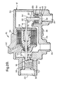
- a first expression of the first embodiment, as seen in Figures 1, 2A, and 2B, is for a solenoid valve 10 including a solenoid valve housing 12, a solenoid actuation rod 14, and first and second tip valves 16 and 18.
- the solenoid valve housing 12 includes first, second, and third valve ports 20, 22, and 24.
- the solenoid actuation rod 14 has first and second ends 26 and 28.
- the first tip valve 16 is actuated by the first end 26 of the solenoid actuation rod 14 to allow or block fluid passage through the first valve port 20, wherein fluid can flow between the first and third valve ports 20 and 24 when the first tip valve 16 is open.
- the second tip valve 18 is actuated by the second end 28 of the solenoid actuation rod 14 to allow or block fluid passage through the second valve port 22, wherein fluid can flow between the second and third valve ports 22 and 24 when the second tip valve 18 is open.
- Figure 2A shows the solenoid actuation rod 14 moved to the right with the first tip valve 16 open and the second tip valve 18 closed
- Figure 2B shows the solenoid actuation rod 14 moved to the left with the second tip valve 18 open and the first tip valve 16 closed.
- the first, second, and third valve ports 20, 22, and 24 are pneumatic ports
- the second valve port 22 is an atmospheric port
- the solenoid valve 10 also includes an air filter 30.
- the filter 30 is designed to keep debris out of the internal mechanism of the solenoid valve 10.
- the solenoid valve housing 12 includes an integrated cover and coil assembly 32 and includes a main body 34.
- the cover and coil assembly 32 contains a solenoid coil 36, an armature 38, and a connector (i.e., an electrical lead) 40.
- the air filter 30, when present, reduces in-rush noise when the solenoid coil 36 is energized.
- the cover and coil assembly 32 consists essentially of plastic and is over-molded over the solenoid coil 36 and the connector 40.
- the main body 34 consists essentially of plastic.
- the solenoid valve 10 includes elastomeric seals 42 and 44 for the first and second tip valves 16 and 18 as shown in Figure 2.
- the elastomeric seals 42 and 44 are over-molded over the main body 34.
- the main body 34 is internally shaped to retain the first and second tip valves 16 and 18 and the air filter 30.
- the main body 34 includes the first, second, and third valve ports 20, 22, and 24.
- the valve ports 20, 22, and 24 are pneumatic ports, and the first and third ports 20 and 24 connect to the primary and secondary working chambers of a vacuum booster.
- the main body 34 includes a mounting flange 46 to secure the solenoid valve 10 to the vacuum booster.
- the cover and coil assembly 32 is sonically welded to the main body 34. In another construction, the cover and coil assembly 32 is fastened to the main body 34 with an intervening perimeter seal.
- the first tip valve 16 has an elongated, rounded first edge 48, and the first end 26 of the solenoid actuation rod 14 pivots the first tip valve 16 about the first edge 48.
- the first edge 48 that the first tip valve 16 pivots on is straight when looking from a top view of Figure 2. This provides a parallel surface for the first tip valve 16 to pivot.
- Such construction allows smooth and consistent operation of the first tip valve 16.
- the first tip valve 16 has a first longitudinal axis 52 which is substantially perpendicular to the solenoid actuation rod 14 when the first tip valve 16 is closed. In one modification, the first tip valve 16 is substantially non-rotatable about the first longitudinal axis 52.
- the first tip valve 16 has a stem 54 coaxially aligned with the first longitudinal axis 52. This allows perpendicular actuation of the first tip valve 16 by the solenoid actuation rod 14. It is noted that the first edge 48 also keeps the stem 54 of the first tip valve 16 perpendicular to the solenoid actuation rod 14.
- the stem 54 has a flat side 56 engageable by the first end 26 of the solenoid actuation rod 14, and surface 58 of the first tip valve 16 is square to prevent rotation of the first tip valve 16.
- the second tip valve 18 has an elongated, rounded second edge 60, and the second end 28 of the solenoid actuation rod 14 pivots the second tip valve 18 about the second edge 60.
- the second edge 60 that the second tip valve 18 pivots on is straight when looking from an end view of Figure 2. This provides a parallel surface for the second tip valve 18 to pivot.
- Such construction allows smooth and consistent operation of the second tip valve 18.
- the second tip valve 18 has a second longitudinal axis 62 which is substantially parallel to the solenoid actuation rod 14 when the second tip valve 18 is closed. In this application, the second tip valve 18 is axially actuated by the solenoid actuation rod 14.
- each tip valve 16 and 18 has a respective spring 64 and 66 that closes the respective tip valve when force is removed from the solenoid actuation rod 14.
- the springs 64 and 66 provide the initial force to seal the respective tip valve on the respective elastomeric seals 42 and 44 over-molded on the main body 34.
- the tip valves 16 and 18 are designed so that the pressure differential provides additional force to seal the valves when they are closed.
- the spring retainers 68 and 70 preload the respective springs 64 and 66 and provide positive location for the springs.
- the primary working chamber valve i.e., the first tip valve 16
- the atmospheric valve i.e., the second tip valve 18
- the solenoid valve 10 when the solenoid valve 10 is energized, the first tip valve 16 is first closed to isolate vacuum from the valve. The second tip valve 18 is then opened to allow airflow into the secondary working chamber of the vacuum booster.
- the solenoid valve 10 is de-energized, the armature return spring 72 forces the solenoid actuation rod 14 back into the rest position.
- the solenoid valve 10 provides a low cost, high flow valve. It is designed for manufacturability. Advantages of one or more of the examples of the solenoid valve 10 include: long stroke actuation by providing linearized magnetics to the solenoid high flow rates from the tip valves and the long stroke, smooth and constant valve operation, positive sealing, small package size, a design for mounting on a vacuum booster of a vehicle brake system, permitting self-apply of a vacuum booster, having the vacuum booster apply to substantially half the runout force, enhancing cold weather performance for vehicle stability enhancement systems, having the air filter prevent vehicle under-hood debris from entering the solenoid valve and provide quiet operation, and providing a fail-safe mode to base brake operation. It is noted that a linearized-magnetics solenoid 74 can be constructed by those skilled in the art, includes the armature 38 attached to the solenoid actuation rod 14 and includes the solenoid coil 36 surrounding the armature 38.
- the solenoid valve 10 is not limited for use on a vacuum booster as can be appreciated by the artisan. It is also noted that, when used with a vacuum booster of a vehicle brake system, the solenoid valve 10 normally allows the primary working chamber of the vacuum booster to be connected to the secondary working chamber for base brake operation. When the solenoid is activated, the primary working chamber is isolated and the secondary working chamber is vented to atmosphere. This allows the booster to self-apply. For many advance brake technologies, it is desired to apply brake pressure quickly.
- the solenoid can be energized by its own controller or more cost effectively, using the anti-lock braking or vehicle stability enhancement controller.
- a second expression of the first embodiment of the invention is for a vacuum booster diaphragm subassembly 76 including a vacuum booster diaphragm 78 and a grommet 80 attached to the vacuum booster diaphragm 78, wherein the vacuum booster diaphragm 78 is disposable in a vacuum booster assembly having primary and secondary working chambers such that the grommet 80 allows fluid flow between the secondary working chamber and a region outside the vacuum booster assembly.
- the vacuum booster diaphragm 78 and the grommet 80 consist essentially of rubber (e.g., urethane rubber) or other elastomeric material.
- the grommet 80 is over-molded over, or integrally molded into, the vacuum booster diaphragm 78.
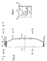
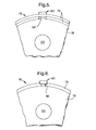
- the grommet 80 includes a grommet opening 82 (seen in Figure 4), an air-flow slot 84 (seen in Figure 5), and a vacuum-booster-housing attachment groove 86 (seen in Figure 6) provided for attachment of the grommet 80 to a matching cutout of the vacuum booster housing.
- the vacuum booster diaphragm subassembly 76 is a modification of a conventional secondary vacuum booster diaphragm which adds a grommet 80 to allow a passageway (i.e., the grommet opening 82 and the air-flow slot 84) from the outside of the vacuum booster into the secondary working chamber of the vacuum booster.
- the grommet 80 provides either a face seal (at location 88) or a radial seal (at location 90) for a device such as a solenoid valve 10.
- the vacuum-booster-housing attachment groove 86 between the grommet and diaphragm seals and prevents the grommet from being pulled into the vacuum booster.
- the front housing flange compresses the secondary diaphragm bead to seal air from leaking into the booster.
- the front housing of the vacuum booster must be modified to accept the diaphragm with the grommet. It has been shown that the grommet design, using rubber, provides enough axial force to seal the bead in the grommet area. In one application, the grommet is reinforced with a rigid insert to help seal this area to overcome any compression set properties of rubber.
- the section of the grommet that is internal to the diaphragm must not interfere with the operation of the diaphragm.
- the slotted feature i.e., the air-flow slot 84 leading from the grommet opening 82 of the passageway to the secondary working chamber allows for airflow into the secondary working chamber of the vacuum booster. This feature also prevents the diaphragm from sealing against the passageway when the booster is evacuated.
- the grommet 80 has straight edges 92 as shown in Fig. 4. In another design, such edges of the grommet are angled which aid in assembly to the vacuum booster housing and which improve the seal around the perimeter of the grommet.
- the vacuum booster diaphragm 78 includes a diaphragm longitudinal axis 94 and a central opening 96 coaxially aligned with the diaphragm longitudinal axis 94, wherein the grommet 80 includes a grommet opening 82 aligned substantially perpendicular to the diaphragm longitudinal axis 94.
- the grommet 80 includes a radially-recessed (as seen in Figure 3) air-flow slot 84 extending outward from the grommet opening 82 and substantially parallel to the diaphragm longitudinal axis 94.
- the grommet 80 includes a vacuum-booster-housing attachment groove 86.
- Advantages of the vacuum booster diaphragm subassembly 76 include providing a low cost means of porting vacuum to the secondary working chamber of the vacuum booster while retaining the seal of the diaphragm bead and with minimal disruption of assembly of the vacuum booster.
- the vacuum booster diaphragm subassembly 76 permits the solenoid valve 10 to attach to the perimeter of the vacuum booster and allows use of the solenoid valve 10 to self apply the booster.
- vacuum boosters contain diaphragms to separate the vacuum chambers from the working chambers. Most diaphragms perform a secondary purpose of sealing atmospheric pressure outside the booster from the vacuum inside the booster. It is sometimes desirable to access the secondary working chamber to monitor vacuum or control the pressure by using a solenoid valve.
- the vacuum booster diaphragm subassembly 76 provides a simple, effective means of providing a passageway to the secondary working chamber. It is also noted that a vacuum booster, such as but not limited to a tie rod design booster, can be used with the solenoid valve 10 without the use of the vacuum booster diaphragm subassembly 76 but with a conventional secondary diaphragm.
- a third expression of the first embodiment of the invention is for a vacuum booster assembly 98 as seen overall in Figure 1.
- the vacuum booster assembly 98 includes a vacuum booster 100 and a solenoid valve 10.
- the vacuum booster 100 of the vacuum booster assembly 98 has a primary working chamber 102 with a primary outside port (also called a primary working chamber port) 104, a primary vacuum chamber 106, a primary diaphragm 108 dividing the primary working and vacuum chambers 102 and 106, a secondary working chamber 110 with a secondary outside port (also called a secondary working chamber port) 112, a secondary vacuum chamber 114, a secondary diaphragm 116 dividing the secondary working and vacuum chambers 110 and 114, and a grommet 80 attached to the secondary diaphragm 116. It is noted that the secondary diaphragm 116 is identical to the vacuum booster diaphragm 78 of the second expression of the first embodiment of the invention.
- the solenoid valve 10 of the vacuum booster assembly 98 includes a solenoid valve housing 12, a solenoid actuation rod 14, and first and second tip valves 16 and 18.
- the solenoid valve housing 12 includes first, second, and third valve ports 20, 22, and 24.
- the solenoid actuation rod 14 has first and second ends 26 and 28.
- the first tip valve 16 is actuated by the first end 26 of the solenoid actuation rod 14 to allow or block fluid passage through the first valve port 20, wherein fluid can flow between the first and third valve ports 20 and 24 when the first tip valve 16 is open.
- the second tip valve 18 is actuated by the second end 28 of the solenoid actuation rod 14 to allow or block fluid passage through the second valve port 22, wherein fluid can flow between the second and third valve ports 22 and 24 when the second tip valve 18 is open.
- the solenoid valve housing 12 is attached to the vacuum booster 100 with the first valve port 20 in fluid communication with the primary outside port 104, with the second valve port 22 in fluid communication with the atmosphere, and with the third valve port 24 in fluid communication with the secondary outside port 112 through the grommet 80.
- the vacuum booster 100 includes a divider plate 118 (such as a steel plate) dividing the primary vacuum chamber 106 and the secondary working chamber 110 and includes a power piston 120 having a passageway 122 connecting the primary and secondary vacuum chambers 106 and 114.
- the secondary vacuum chamber 114 includes a port (omitted from Figure 1) leading to engine vacuum.
- the solenoid valve 10 includes the previously-discussed optional features of the solenoid valve 10 discussed in the first expression of the first embodiment of the invention.
- the secondary diaphragm 116 and/or the grommet 80 include the previously-discussed optional features of the vacuum booster diaphragm 78 and/or the grommet 80 discussed in the second expression of the first embodiment of the invention.
Landscapes
- Engineering & Computer Science (AREA)
- General Engineering & Computer Science (AREA)
- Mechanical Engineering (AREA)
- Braking Systems And Boosters (AREA)
- Magnetically Actuated Valves (AREA)
- Details Of Valves (AREA)
Abstract
Description
Claims (20)
- A solenoid valve (10) comprising:a) a solenoid valve housing (12) including first, second, and third valve ports (20, 22, and 24);b) a solenoid actuation rod (14) having first and second ends (26 and 28);c) a first tip valve (16) actuated by the first end (26) of the solenoid actuation rod to allow or block fluid passage through the first valve port (20), wherein fluid can flow between the first and third valve ports (20 and 24)when the first tip valve is open; andd) a second tip valve (18) actuated by the second end (28) of the solenoid actuation rod to allow or block fluid passage through the second valve port (22), wherein fluid can flow between the second and third valve ports (22 and 24) when the second tip valve is open.
- The solenoid valve of claim 1, wherein the first, second, and third valve ports are pneumatic ports, wherein the second valve port is an atmospheric port, and wherein the solenoid valve also includes an air filter (30) disposed in the second valve port.
- The solenoid valve of claim 1, also including a linearized-magnetics solenoid (74) having an armature (38) attached to the solenoid actuation rod and having a solenoid coil (36) surrounding the armature.
- The solenoid valve of claim 1, wherein the first tip valve has an elongated, rounded first edge (48), and wherein the first end of the solenoid actuation rod pivots the first tip valve about the first edge.
- The solenoid valve of claim 4, wherein the first tip valve has a first longitudinal axis (52) which is substantially perpendicular to the solenoid actuation rod when the first tip valve is closed.
- The solenoid valve of claim 5, wherein the first tip valve is substantially non-rotatable about the first longitudinal axis.
- The solenoid valve of claim 6, wherein the first tip valve has a stem (54) coaxially aligned with the first longitudinal axis, and wherein the stem has a flat side (56) engageable by the first end of the solenoid actuation rod.
- The solenoid valve of claim 1, wherein the second tip valve has an elongated, rounded second edge (60), and wherein the second end of the solenoid actuation rod pivots the second tip valve about the second edge.
- The solenoid valve of claim 8, wherein the second tip valve has a second longitudinal axis (62) which is substantially parallel to the solenoid actuation rod when the second tip valve is closed.
- A solenoid valve comprising:a) a solenoid valve housing including first, second, and third valve ports;b) a solenoid actuation rod having first and second ends;c) a first tip valve actuated by the first end of the solenoid actuation rod to allow or block fluid passage through the first valve port, wherein fluid can flow between the first and third valve ports when the first tip valve is open, wherein the first tip valve has an elongated, rounded first edge, and wherein the first end of the solenoid actuation rod pivots the first tip valve about the first edge;d) a second tip valve actuated by the second end of the solenoid actuation rod to allow or block fluid passage through the second valve port, wherein fluid can flow between the second and third valve ports when the second tip valve is open, wherein the second tip valve has an elongated, rounded second edge, and wherein the second end of the solenoid actuation rod pivots the second tip valve about the second edge; ande) a linearized-magnetics solenoid having an armature attached to the solenoid actuation rod and having a solenoid coil surrounding the armature.
- A vacuum booster diaphragm subassembly (76) comprising:a) a vacuum booster diaphragm (78); andb) a grommet (80) attached to the vacuum booster diaphragm, wherein the vacuum booster diaphragm is disposable in a vacuum booster assembly (98) having primary and secondary working chambers (102 and 110) such that the grommet allows fluid flow between the secondary working chamber (110) and a region outside the vacuum booster assembly.
- The vacuum booster diaphragm subassembly of claim 11, wherein the vacuum booster diaphragm includes a diaphragm longitudinal axis (94) and a central opening (96) coaxially aligned with the diaphragm longitudinal axis, and wherein the grommet includes a grommet opening (82) aligned substantially perpendicular to the diaphragm longitudinal axis.
- The vacuum booster diaphragm subassembly of claim 12, wherein the grommet includes a radially-recessed air-flow slot (84) extending outward from the grommet opening and substantially parallel to the diaphragm longitudinal axis.
- The vacuum booster diaphragm subassembly of claim 13, wherein the grommet includes a vacuum-booster-housing attachment groove (86).
- A vacuum booster diaphragm subassembly comprising:wherein the vacuum booster diaphragm is disposable in a vacuum booster assembly having primary and secondary working chambers such that the grommet allows fluid flow between the secondary working chamber and a region outside the vacuum booster assembly,a) a vacuum booster diaphragm; andb) a grommet attached to the vacuum booster diaphragm,
wherein the vacuum booster diaphragm includes a diaphragm longitudinal axis and a central opening coaxially aligned with the diaphragm longitudinal axis,
wherein the grommet includes a grommet opening aligned substantially perpendicular to the diaphragm longitudinal axis,
wherein the grommet includes a radially-recessed air-flow slot extending outward from the grommet opening and substantially parallel to the diaphragm longitudinal axis, and
wherein the grommet includes a vacuum-booster-housing attachment groove. - A vacuum booster assembly (98) comprising:a) a vacuum booster (100) including:1) a primary working chamber (102) with a primary outside port (104);2) a primary vacuum chamber (106);3) a primary diaphragm (108) dividing the primary working and vacuum chambers;4) a secondary working chamber (110) with a secondary outside port (112);5) a secondary vacuum chamber (114);6) a secondary diaphragm (116) dividing the secondary working and vacuum chambers; and7) a grommet (80) attached to the secondary diaphragm; andb) solenoid valve (10) including:1) a solenoid valve housing (12) including first, second, and third valve ports (20, 22, and 24), wherein the solenoid valve housing is attached to the vacuum booster with the first valve port (20) in fluid communication with the primary port, with the second valve port (22) in fluid communication with the atmosphere, and with the third valve port (24) in fluid communication with the secondary port through the grommet;2) a solenoid actuation rod (14) having first and second ends (26 and 28);3) a first tip valve (16) actuated by the first end (26) of the solenoid actuation rod to allow or block fluid passage through the first valve port, wherein fluid can flow between the first and third valve ports when the first tip valve is open; and4) a second tip valve (18) actuated by the second end (28) of the solenoid actuation rod to allow or block fluid passage through the second valve port, wherein fluid can flow between the second and third valve ports when the second tip valve is open.
- The vacuum booster assembly of claim 16, wherein the solenoid valve includes a linearized-magnetics solenoid 74) having an armature (38) attached to the solenoid actuation rod and having a solenoid coil (36) surrounding the armature.
- The vacuum booster assembly of claim 16, wherein the first tip valve has an elongated, rounded first edge (48), wherein the first end of the solenoid actuation rod pivots the first tip valve about the first edge, wherein the second tip valve has an elongated, rounded second edge (60), wherein the second end of the solenoid actuation rod pivots the second tip valve about the second edge.
- The vacuum booster assembly of claim 16, wherein the secondary diaphragm includes a diaphragm longitudinal axis (94) and a central opening (96) coaxially aligned with the diaphragm longitudinal axis, wherein the grommet includes a grommet opening (82) aligned substantially perpendicular to the diaphragm longitudinal axis, and wherein the grommet includes a radially-recessed air-flow slot (84) extending outward from the grommet opening and substantially parallel to the diaphragm longitudinal axis.
- The vacuum booster assembly of claim 16, wherein the grommet includes a vacuum-booster-housing attachment groove (86).
Applications Claiming Priority (2)
| Application Number | Priority Date | Filing Date | Title |
|---|---|---|---|
| US35747602P | 2002-02-15 | 2002-02-15 | |
| US357476P | 2002-02-15 |
Publications (3)
| Publication Number | Publication Date |
|---|---|
| EP1336787A2 true EP1336787A2 (en) | 2003-08-20 |
| EP1336787A3 EP1336787A3 (en) | 2003-12-10 |
| EP1336787B1 EP1336787B1 (en) | 2006-05-03 |
Family
ID=27623221
Family Applications (1)
| Application Number | Title | Priority Date | Filing Date |
|---|---|---|---|
| EP20030075192 Expired - Lifetime EP1336787B1 (en) | 2002-02-15 | 2003-01-21 | Solenoid valve, vacuum booster diaphragm subassembly, and vacuum booster assembly |
Country Status (3)
| Country | Link |
|---|---|
| US (1) | US6748846B2 (en) |
| EP (1) | EP1336787B1 (en) |
| DE (1) | DE60304910T2 (en) |
Families Citing this family (7)
| Publication number | Priority date | Publication date | Assignee | Title |
|---|---|---|---|---|
| US7350622B2 (en) * | 2004-02-13 | 2008-04-01 | Precision Rotary Equipment, Inc. | Powdered graphite applicator |
| US7673950B2 (en) * | 2004-11-04 | 2010-03-09 | Fulks Gary C | Vehicle autonomous brake-apply system and method |
| US20070228311A1 (en) * | 2006-03-28 | 2007-10-04 | Beneker Gerrit V | Pressure balanced valve |
| DE102015219182B4 (en) * | 2015-10-05 | 2019-07-04 | Conti Temic Microelectronic Gmbh | Pneumatic solenoid valve |
| DE102015219195B4 (en) * | 2015-10-05 | 2019-07-04 | Conti Temic Microelectronic Gmbh | Pneumatic solenoid valve |
| DE102015219197B4 (en) * | 2015-10-05 | 2019-07-04 | Conti Temic Microelectronic Gmbh | Pneumatic solenoid valve |
| US11047501B2 (en) * | 2017-07-14 | 2021-06-29 | Robertshaw Controls Company | Normally open gas valve |
Family Cites Families (23)
| Publication number | Priority date | Publication date | Assignee | Title |
|---|---|---|---|---|
| US479795A (en) * | 1892-08-02 | Valve-controller | ||
| FR866140A (en) * | 1940-03-04 | 1941-06-26 | Development of fire control devices | |
| US2426779A (en) * | 1943-06-14 | 1947-09-02 | Kellogg M W Co | Relay valve apparatus |
| US3222999A (en) | 1962-12-31 | 1965-12-14 | Bendix Corp | Fluid pressure servomotor |
| GB1100379A (en) | 1964-09-30 | 1968-01-24 | Bendix Corp | Fluid pressure servo-motor |
| US3362298A (en) * | 1965-10-18 | 1968-01-09 | Bendix Corp | Vehicle control system |
| US3362297A (en) * | 1966-09-26 | 1968-01-09 | Bendix Corp | Fluid pressure servomotor |
| DE2119191B2 (en) | 1971-04-20 | 1972-07-13 | Heilmeier & Weinlem, Fabrik fur OeI Hydraulik, 8000 München | Double-acting solenoid operated multi-way valve |
| JPS596561U (en) * | 1982-07-06 | 1984-01-17 | アイシン精機株式会社 | Tandem type brake booster for vehicles |
| US4632208A (en) * | 1983-12-20 | 1986-12-30 | Tokico Ltd. | Vehicle braking system |
| GB8719299D0 (en) | 1987-08-14 | 1987-09-23 | Lucas Ind Plc | Traction control system |
| GB8920588D0 (en) | 1989-09-12 | 1989-10-25 | Lucas Ind Plc | Improvements relating to a vacuum servo unit for use in traction control |
| DE3906529A1 (en) * | 1988-11-03 | 1990-09-06 | Teves Gmbh Alfred | SLIP-CONTROLLED BRAKE SYSTEM |
| GB8901066D0 (en) | 1989-01-18 | 1989-03-15 | Lucas Ind Plc | Improvements in fluidpressure operated boosters for vehicle braking systems |
| DE3943002A1 (en) | 1989-12-27 | 1991-07-04 | Lucas Ind Plc | VEHICLE BRAKE SYSTEM |
| US5251667A (en) | 1992-10-20 | 1993-10-12 | Emerson Electric Co. | Three-way solenoid operated control valve |
| DE4309850C2 (en) | 1993-03-26 | 1996-12-12 | Lucas Ind Plc | Brake booster system for regulating a brake pressure with a brake booster |
| DE19750383C1 (en) | 1997-11-13 | 1998-12-24 | Lucas Ind Plc | Pneumatic brake booster for motor vehicle |
| US6027099A (en) | 1998-03-20 | 2000-02-22 | Snap-On Tools Company | Tip valve for pneumatic tool |
| DE19921945B4 (en) | 1999-05-12 | 2004-04-15 | ZF Lemförder Metallwaren AG | Tandem brake booster for motor vehicles |
| US6301883B1 (en) | 1999-08-16 | 2001-10-16 | Delphi Technologies, Inc. | Vehicle brake booster with supplemental vacuum assist |
| US6364429B1 (en) | 2000-10-02 | 2002-04-02 | Delphi Technologies, Inc. | Vehicle brake boost assist control |
| US6623088B2 (en) | 2001-03-13 | 2003-09-23 | Delphi Technologies, Inc. | Vehicle brake boost assist control |
-
2002
- 2002-04-04 US US10/115,652 patent/US6748846B2/en not_active Expired - Fee Related
-
2003
- 2003-01-21 DE DE2003604910 patent/DE60304910T2/en not_active Expired - Lifetime
- 2003-01-21 EP EP20030075192 patent/EP1336787B1/en not_active Expired - Lifetime
Also Published As
| Publication number | Publication date |
|---|---|
| EP1336787A3 (en) | 2003-12-10 |
| US6748846B2 (en) | 2004-06-15 |
| DE60304910T2 (en) | 2006-11-09 |
| EP1336787B1 (en) | 2006-05-03 |
| US20030154852A1 (en) | 2003-08-21 |
| DE60304910D1 (en) | 2006-06-08 |
Similar Documents
| Publication | Publication Date | Title |
|---|---|---|
| US6748846B2 (en) | Solenoid valve, vacuum booster diaphragm subassembly, and vacuum booster assembly | |
| SK278488B6 (en) | The valve assembly for controlling pneumatic brake booster | |
| CN106536304A (en) | Valve unit for modulating the pressure in pneumatic brake system | |
| CN115989164B (en) | Sealing assembly for spring brake actuators | |
| US20080116741A1 (en) | Ventilation Device for a Combined Spring Accumulator and Operating Brake Cylinder | |
| US20040035472A1 (en) | Valve arrangement having electromagnetic actuation | |
| US6988707B2 (en) | Anti-lock brake equipment solenoid valve | |
| EP1967778A1 (en) | Biased actuator systems | |
| JP2000104662A (en) | air compressor | |
| KR20240133276A (en) | Check valve and brake system including the same | |
| EP1781518A1 (en) | Valve assembly | |
| HUT56777A (en) | Pressure controlling valve unit particularly for the pneumatic brake assemblies of motor vehicles | |
| US5105722A (en) | Mechanically controlled power booster | |
| CN100422012C (en) | Pneumatic valve and braking system comprising such a valve | |
| CA2563226C (en) | Pressure control valve | |
| US6378548B1 (en) | Varying size diaphragm valve assemblies utilizing diaphragm of uniform size | |
| US6305759B1 (en) | Trailer ABS modulator with direct exhaust and control line/volume drain capability | |
| US7302882B2 (en) | Jump force vacuum booster | |
| US20040012255A1 (en) | Pneumatic booster comprising tubular intake and equalizing valves | |
| WO2002087938A8 (en) | Electropneumatic control valve with a seal arrangement | |
| JPH0134178B2 (en) | ||
| US6912946B2 (en) | System and method for improved controlled airflow within a vacuum booster system | |
| JPS62279164A (en) | Brake boost device | |
| JPH07269734A (en) | Solenoid valve device | |
| CN210912398U (en) | Electromagnetic valve and hydraulic device |
Legal Events
| Date | Code | Title | Description |
|---|---|---|---|
| PUAI | Public reference made under article 153(3) epc to a published international application that has entered the european phase |
Free format text: ORIGINAL CODE: 0009012 |
|
| AK | Designated contracting states |
Designated state(s): AT BE BG CH CY CZ DE DK EE ES FI FR GB GR HU IE IT LI LU MC NL PT SE SI SK TR |
|
| AX | Request for extension of the european patent |
Extension state: AL LT LV MK RO |
|
| RIC1 | Information provided on ipc code assigned before grant |
Ipc: 7B 60T 13/52 B Ipc: 7F 16K 11/10 B Ipc: 7F 16K 31/06 A |
|
| PUAL | Search report despatched |
Free format text: ORIGINAL CODE: 0009013 |
|
| AK | Designated contracting states |
Kind code of ref document: A3 Designated state(s): AT BE BG CH CY CZ DE DK EE ES FI FR GB GR HU IE IT LI LU MC NL PT SE SI SK TR |
|
| AX | Request for extension of the european patent |
Extension state: AL LT LV MK RO |
|
| RIC1 | Information provided on ipc code assigned before grant |
Ipc: 7F 16K 31/06 A Ipc: 7F 16K 11/10 B Ipc: 7B 60T 13/567 B Ipc: 7B 60T 13/52 B Ipc: 7B 60T 13/72 B Ipc: 7B 60T 13/563 B |
|
| 17P | Request for examination filed |
Effective date: 20040611 |
|
| AKX | Designation fees paid |
Designated state(s): DE FR GB |
|
| 17Q | First examination report despatched |
Effective date: 20040831 |
|
| GRAP | Despatch of communication of intention to grant a patent |
Free format text: ORIGINAL CODE: EPIDOSNIGR1 |
|
| RBV | Designated contracting states (corrected) |
Designated state(s): DE FR GB IT |
|
| GRAS | Grant fee paid |
Free format text: ORIGINAL CODE: EPIDOSNIGR3 |
|
| GRAA | (expected) grant |
Free format text: ORIGINAL CODE: 0009210 |
|
| AK | Designated contracting states |
Kind code of ref document: B1 Designated state(s): DE FR GB IT |
|
| PG25 | Lapsed in a contracting state [announced via postgrant information from national office to epo] |
Ref country code: IT Free format text: LAPSE BECAUSE OF FAILURE TO SUBMIT A TRANSLATION OF THE DESCRIPTION OR TO PAY THE FEE WITHIN THE PRESCRIBED TIME-LIMIT;WARNING: LAPSES OF ITALIAN PATENTS WITH EFFECTIVE DATE BEFORE 2007 MAY HAVE OCCURRED AT ANY TIME BEFORE 2007. THE CORRECT EFFECTIVE DATE MAY BE DIFFERENT FROM THE ONE RECORDED. Effective date: 20060503 |
|
| REG | Reference to a national code |
Ref country code: GB Ref legal event code: FG4D |
|
| REF | Corresponds to: |
Ref document number: 60304910 Country of ref document: DE Date of ref document: 20060608 Kind code of ref document: P |
|
| ET | Fr: translation filed | ||
| PLBE | No opposition filed within time limit |
Free format text: ORIGINAL CODE: 0009261 |
|
| STAA | Information on the status of an ep patent application or granted ep patent |
Free format text: STATUS: NO OPPOSITION FILED WITHIN TIME LIMIT |
|
| 26N | No opposition filed |
Effective date: 20070206 |
|
| PGFP | Annual fee paid to national office [announced via postgrant information from national office to epo] |
Ref country code: FR Payment date: 20120202 Year of fee payment: 10 |
|
| PGFP | Annual fee paid to national office [announced via postgrant information from national office to epo] |
Ref country code: GB Payment date: 20120118 Year of fee payment: 10 Ref country code: IT Payment date: 20120114 Year of fee payment: 10 |
|
| GBPC | Gb: european patent ceased through non-payment of renewal fee |
Effective date: 20130121 |
|
| REG | Reference to a national code |
Ref country code: FR Ref legal event code: ST Effective date: 20130930 |
|
| PG25 | Lapsed in a contracting state [announced via postgrant information from national office to epo] |
Ref country code: FR Free format text: LAPSE BECAUSE OF NON-PAYMENT OF DUE FEES Effective date: 20130131 Ref country code: GB Free format text: LAPSE BECAUSE OF NON-PAYMENT OF DUE FEES Effective date: 20130121 |
|
| PG25 | Lapsed in a contracting state [announced via postgrant information from national office to epo] |
Ref country code: IT Free format text: LAPSE BECAUSE OF NON-PAYMENT OF DUE FEES Effective date: 20130121 |
|
| PGFP | Annual fee paid to national office [announced via postgrant information from national office to epo] |
Ref country code: DE Payment date: 20180110 Year of fee payment: 16 |
|
| REG | Reference to a national code |
Ref country code: DE Ref legal event code: R119 Ref document number: 60304910 Country of ref document: DE |
|
| PG25 | Lapsed in a contracting state [announced via postgrant information from national office to epo] |
Ref country code: DE Free format text: LAPSE BECAUSE OF NON-PAYMENT OF DUE FEES Effective date: 20190801 |
|
| REG | Reference to a national code |
Ref country code: DE Ref legal event code: R081 Ref document number: 60304910 Country of ref document: DE Owner name: BWI COMPANY LIMITED S.A., LU Free format text: FORMER OWNER: DELPHI TECHNOLOGIES, INC., TROY, MICH., US Ref country code: DE Ref legal event code: R082 Ref document number: 60304910 Country of ref document: DE |