EP1336762A1 - Improvements in diffusion pumps - Google Patents
Improvements in diffusion pumps Download PDFInfo
- Publication number
- EP1336762A1 EP1336762A1 EP03250705A EP03250705A EP1336762A1 EP 1336762 A1 EP1336762 A1 EP 1336762A1 EP 03250705 A EP03250705 A EP 03250705A EP 03250705 A EP03250705 A EP 03250705A EP 1336762 A1 EP1336762 A1 EP 1336762A1
- Authority
- EP
- European Patent Office
- Prior art keywords
- working fluid
- pump
- diffusion pump
- valve
- tank
- Prior art date
- Legal status (The legal status is an assumption and is not a legal conclusion. Google has not performed a legal analysis and makes no representation as to the accuracy of the status listed.)
- Withdrawn
Links
- 238000009792 diffusion process Methods 0.000 title claims abstract description 35
- 239000012530 fluid Substances 0.000 claims abstract description 32
- 238000012544 monitoring process Methods 0.000 claims description 7
- 235000014676 Phragmites communis Nutrition 0.000 claims description 5
- 238000001816 cooling Methods 0.000 description 3
- XLYOFNOQVPJJNP-UHFFFAOYSA-N water Substances O XLYOFNOQVPJJNP-UHFFFAOYSA-N 0.000 description 2
- 238000009835 boiling Methods 0.000 description 1
- 239000002826 coolant Substances 0.000 description 1
- 239000012809 cooling fluid Substances 0.000 description 1
- 239000000498 cooling water Substances 0.000 description 1
- 230000001934 delay Effects 0.000 description 1
- 239000011521 glass Substances 0.000 description 1
- 238000010438 heat treatment Methods 0.000 description 1
- 238000012423 maintenance Methods 0.000 description 1
- QSHDDOUJBYECFT-UHFFFAOYSA-N mercury Chemical compound [Hg] QSHDDOUJBYECFT-UHFFFAOYSA-N 0.000 description 1
- 229910052753 mercury Inorganic materials 0.000 description 1
Images


Classifications
-
- F—MECHANICAL ENGINEERING; LIGHTING; HEATING; WEAPONS; BLASTING
- F04—POSITIVE - DISPLACEMENT MACHINES FOR LIQUIDS; PUMPS FOR LIQUIDS OR ELASTIC FLUIDS
- F04F—PUMPING OF FLUID BY DIRECT CONTACT OF ANOTHER FLUID OR BY USING INERTIA OF FLUID TO BE PUMPED; SIPHONS
- F04F9/00—Diffusion pumps
- F04F9/08—Control
-
- F—MECHANICAL ENGINEERING; LIGHTING; HEATING; WEAPONS; BLASTING
- F04—POSITIVE - DISPLACEMENT MACHINES FOR LIQUIDS; PUMPS FOR LIQUIDS OR ELASTIC FLUIDS
- F04F—PUMPING OF FLUID BY DIRECT CONTACT OF ANOTHER FLUID OR BY USING INERTIA OF FLUID TO BE PUMPED; SIPHONS
- F04F9/00—Diffusion pumps
Definitions
- the present invention relates to vacuum pumps of the type known as diffusion pumps.
- Diffusion pumps are well known and widely used for the attainment of high and ultra high vacua. When used with modern working fluids and accessories, they can produce pressures approaching 10 -10 mbar. The pumps are generally incapable of exhausting directly to the atmosphere and require the use of a backing pump, commonly an oil sealed rotary vane vacuum pump, in conjunction with the diffusion pump itself.
- Diffusion pumps generally comprise a substantially cylindrical outer body which is cooled by, for example coils helically wound around the outside of the body through which cooling water can be circulated or alternatively by air cooled fins attached to the outside of the body.
- the outer body Within the outer body is positioned a hollow "chimney" sitting at, or close to, the base of the outer body and which tapers (continuously or, more usually, in stages) upwardly from the base.
- the chimney is generally contained within the outer body and is positioned substantially concentrically therein.
- top cap having a generally circular portion of somewhat larger diameter than the top of the chimney and positioned symmetrically with regard to the chimney and having a downwardly projected annular side portion whose lower edge is somewhat beneath the upper edge of the chimney.
- the top cap is therefore substantially an inverted "cup shaped" component positioned about the top of the chimney with a circular or annular passageway therebetween.
- the top cap and the adjacent portion of the chimney defining the annular passageway is known as a "jet stage".
- a heat source is provided in the base of the outer body, preferably in the form of an electric heater, and, prior to use of the pump, a working fluid is placed in the base of the body to a height above the lower edge of the chimney positioned within the body.
- the fluid is usually a low vapour pressure oil although some versions of diffusion pumps use mercury.
- a pump inlet is positioned in the outer body above the top cap and an outlet in the side of the body towards the base of the chimney but above the oil level.
- the outlet is normally connected to a backing pump as previously described.
- the backing (rotary) pump is turned on and left running continuously, a pressure of at least 0.1 mbar being required on the exhaust side of the diffusion pump.
- the cooling system (water or air) for the outer body is turned on and the oil can now be heated by the heater for, for example fifteen to twenty minutes, when it begins to boil. Hot vapour rises up the chimney and forms (aided by the taper) a relatively high oil pressure within the chimney. The vapour is then urged through the passageway between the chimney and the top cap, the jet stage, to an area of much lower pressure and creates an annular vapour jet.
- This jet is designed to move at a high velocity (sometimes supersonic) and impinges on the inside surface of the cooled outer body where the vapour condenses and condensed oil flows down the inside wall of the outer body and returns to the oil reservoir (boiler) at the base of the body.
- the working fluid is held within the body of the diffusion pump and is consumed due to vapour losses. Provided that pump cooling is adequate the rate of these losses is determined by the mass flow through the pump. Generally, the working fluid needs replenishing from time to time.
- the pump can operate for longer periods at full throughput without oil maintenance, for example for a year or more.
- a novel combination comprises a diffusion pump, a reservoir containing a working fluid spaced from the diffusion pump and pipework means for allowing the flow of the working fluid from the reservoir towards the diffusion pump.
- the reservoir includes a tank for containing the working fluid, the tank being provided with a transparent window for viewing the level of the working fluid within the tank.
- a valve for example a solenoid valve is provided which is movable between a first closed position to prevent the flow of working fluid out from the reservoir to a second open position.
- the movement of the valve between said first and second positions may be controlled by a level monitoring sensor which includes a vertically mounted float and a reed switch and is connected to the diffusion pump via said pipework means.
- a known diffusion pump 1 comprises a hollow outer body 2 of generally circular cross section, a major portion of which is provided with cooling coils 4 for the circulation of cooling fluid, for example water.
- the body 2 includes a base 6 and vapour chimney 8 is positioned within the outer body 2 and extends upwardly from the base 6.
- a working fluid 7 is located in the base of the chimney 8 and, as shown, an electric heater 10 is located immediately below the base 6.
- the chimney is formed with a single jet stage 12.
- the diffusion pump 1 also includes an outlet 14 for connection to a backing vacuum pump and an inlet 16 for connection to a chamber to be evaeuated. As shown, the jet stage 12 is located adjacent the inlet 16.
- the backing pump is turned on to reduce the pressure within the diffusion pump 1 and a coolant is passed through the coils 4.
- Heating of the working fluid 7 by means of the heater 10 causes boiled vapour to rise up the chimney 8 in the manner described earlier and to emerge through the jet stage 12 and thereafter to fall downwardly in the general direction of the base 6 along the inner surface of the outer body 2.
- the diffusion pump 1 is connected to a high capacity reservoir.
- the high capacity reservoir 20 comprises a tank 22 for working fluid connected to a support arm 24. As shown, at its upper end there is a transparent window in the form of a glass disc 26 for viewing the level of working fluid in the tank 22. At its lower end there is provided a normally closed valve 28 for example a solenoid valve. The actuation of the valve 28 is controlled by a level monitoring sensor, in this case a pot assembly 30 which contains a vertically mounted float 29 and a reed switch 31. The pot assembly 30 is connected to the working fluid fill and drain ports of the diffusion pump body 2 via connections 32, 34.
- the reed switch 31 is actuated and energises the solenoid valve 28. This allows working fluid to pass from the tank 22, through the solenoid valve 28 and the pot assembly 30 towards the diffusion pump 1 via connections 32, 34.
- the tank 22 is sealed under vacuum so that the fresh working fluid entering the diffusion pump is fully degassed before entering the body 2.
- the monitoring pot assembly 30 senses the fluid level when the pump 1 is fully operational.
- a head of fluid is maintained on the outside of the pump as a consequence of the pressure difference across the boiler stage. This tends to cause an increase in the height of the fluid level outside the jet stage 12.
- This pressure difference is the driving force that generates the vapour jets.
- This head takes a certain period of time to become established when the pump is started from cold. In the warm up condition the fluid level can be low and could cause emptying of the tank 22.
- this has been overcome by the inclusion of a thermal snap switch that causes the monitoring circuit to lag until the operational temperature of the pump base 6 has been reached.
Landscapes
- Engineering & Computer Science (AREA)
- Mechanical Engineering (AREA)
- General Engineering & Computer Science (AREA)
- Jet Pumps And Other Pumps (AREA)
- Applications Or Details Of Rotary Compressors (AREA)
Abstract
A combination including a diffusion pump 1 and a reservoir 20 of high volumetric
capacity positioned remotely from the pump. The reservoir 20 contains a working
fluid and is connected to the diffusion pump 1 via a valve 28 and pipework.
Description
- The present invention relates to vacuum pumps of the type known as diffusion pumps.
- Diffusion pumps are well known and widely used for the attainment of high and ultra high vacua. When used with modern working fluids and accessories, they can produce pressures approaching 10-10 mbar. The pumps are generally incapable of exhausting directly to the atmosphere and require the use of a backing pump, commonly an oil sealed rotary vane vacuum pump, in conjunction with the diffusion pump itself.
- Diffusion pumps generally comprise a substantially cylindrical outer body which is cooled by, for example coils helically wound around the outside of the body through which cooling water can be circulated or alternatively by air cooled fins attached to the outside of the body.
- Within the outer body is positioned a hollow "chimney" sitting at, or close to, the base of the outer body and which tapers (continuously or, more usually, in stages) upwardly from the base. The chimney is generally contained within the outer body and is positioned substantially concentrically therein.
- Across the top of the chimney but not in contact therewith is a top cap having a generally circular portion of somewhat larger diameter than the top of the chimney and positioned symmetrically with regard to the chimney and having a downwardly projected annular side portion whose lower edge is somewhat beneath the upper edge of the chimney. The top cap is therefore substantially an inverted "cup shaped" component positioned about the top of the chimney with a circular or annular passageway therebetween. The top cap and the adjacent portion of the chimney defining the annular passageway is known as a "jet stage".
- A heat source is provided in the base of the outer body, preferably in the form of an electric heater, and, prior to use of the pump, a working fluid is placed in the base of the body to a height above the lower edge of the chimney positioned within the body. The fluid is usually a low vapour pressure oil although some versions of diffusion pumps use mercury.
- A pump inlet is positioned in the outer body above the top cap and an outlet in the side of the body towards the base of the chimney but above the oil level. The outlet is normally connected to a backing pump as previously described.
- In use of pumps of this type, the backing (rotary) pump is turned on and left running continuously, a pressure of at least 0.1 mbar being required on the exhaust side of the diffusion pump. The cooling system (water or air) for the outer body is turned on and the oil can now be heated by the heater for, for example fifteen to twenty minutes, when it begins to boil. Hot vapour rises up the chimney and forms (aided by the taper) a relatively high oil pressure within the chimney. The vapour is then urged through the passageway between the chimney and the top cap, the jet stage, to an area of much lower pressure and creates an annular vapour jet. This jet is designed to move at a high velocity (sometimes supersonic) and impinges on the inside surface of the cooled outer body where the vapour condenses and condensed oil flows down the inside wall of the outer body and returns to the oil reservoir (boiler) at the base of the body.
- With the diffusion pump turned on, gas molecules arriving at the inlet of the diffusion pump are likely to collide with the much heavier oil vapour molecules and be provided with a velocity component which will direct the gas molecules towards the outlet of the diffusion pump where they will be subsequently removed from the diffusion pump via the backing pump. A pressure difference is thereby established across the continuously flowing vapour jet.
- Conventionally, as previously explained, the working fluid is held within the body of the diffusion pump and is consumed due to vapour losses. Provided that pump cooling is adequate the rate of these losses is determined by the mass flow through the pump. Generally, the working fluid needs replenishing from time to time.
- It is an aim of the present invention to connect a reservoir of high volumetric capacity to the diffusion pump, the reservoir being positioned remotely from the pump body to minimise the thermal requirements of the pump that would result from having to keep a large volume of working fluid at boiling point continuously. With the reservoir connected to the pump, the pump can operate for longer periods at full throughput without oil maintenance, for example for a year or more.
- According to the present invention, a novel combination comprises a diffusion pump, a reservoir containing a working fluid spaced from the diffusion pump and pipework means for allowing the flow of the working fluid from the reservoir towards the diffusion pump.
- Preferably, the reservoir includes a tank for containing the working fluid, the tank being provided with a transparent window for viewing the level of the working fluid within the tank.
- In one embodiment, a valve, for example a solenoid valve is provided which is movable between a first closed position to prevent the flow of working fluid out from the reservoir to a second open position.
- The movement of the valve between said first and second positions may be controlled by a level monitoring sensor which includes a vertically mounted float and a reed switch and is connected to the diffusion pump via said pipework means.
- An embodiment of the invention will now be described, by way of example, reference being made to the Figures of the accompanying diagrammatic drawings in which:
- Figure 1 is a cross section through a known diffusion pump;
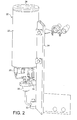
- Figure 2 is a perspective view of a high capacity oil reservoir ready for connection to a diffusion pump according to the present invention; and
- Figure 3 is a diagrammatic sketch showing the high capacity reservoir of Figure 2 operatively connected to a diffusion pump.
-
- Referring first to Figure 1, a known
diffusion pump 1 comprises a hollowouter body 2 of generally circular cross section, a major portion of which is provided with cooling coils 4 for the circulation of cooling fluid, for example water. Thebody 2 includes abase 6 andvapour chimney 8 is positioned within theouter body 2 and extends upwardly from thebase 6. A workingfluid 7 is located in the base of thechimney 8 and, as shown, anelectric heater 10 is located immediately below thebase 6. - As shown, the chimney is formed with a
single jet stage 12. - The
diffusion pump 1 also includes anoutlet 14 for connection to a backing vacuum pump and aninlet 16 for connection to a chamber to be evaeuated. As shown, thejet stage 12 is located adjacent theinlet 16. - In use, when the
inlet 16 is attached to the chamber to be evacuated, the backing pump is turned on to reduce the pressure within thediffusion pump 1 and a coolant is passed through the coils 4. - Heating of the working
fluid 7 by means of theheater 10 causes boiled vapour to rise up thechimney 8 in the manner described earlier and to emerge through thejet stage 12 and thereafter to fall downwardly in the general direction of thebase 6 along the inner surface of theouter body 2. - According to the present invention, the
diffusion pump 1 is connected to a high capacity reservoir. - Referring now to Figures 2 and 3, the
high capacity reservoir 20 comprises atank 22 for working fluid connected to asupport arm 24. As shown, at its upper end there is a transparent window in the form of aglass disc 26 for viewing the level of working fluid in thetank 22. At its lower end there is provided a normally closedvalve 28 for example a solenoid valve. The actuation of thevalve 28 is controlled by a level monitoring sensor, in this case apot assembly 30 which contains a vertically mountedfloat 29 and areed switch 31. Thepot assembly 30 is connected to the working fluid fill and drain ports of thediffusion pump body 2 viaconnections - In use, when the
float 29 drops to a predetermined level as a result of the working fluid level dropping within thediffusion pump body 2, thereed switch 31 is actuated and energises thesolenoid valve 28. This allows working fluid to pass from thetank 22, through thesolenoid valve 28 and thepot assembly 30 towards thediffusion pump 1 viaconnections - To avoid the
reed switch 31 fluttering about its switching point, as its hysteresis is limited and the working fluid level oscillates slightly, there is an electronic timer circuit that delays re-closure of thesolenoid valve 28. This ensures that an adequate volume of working fluid is fed into thebody 2 with minimum valve actuations. - The
tank 22 is sealed under vacuum so that the fresh working fluid entering the diffusion pump is fully degassed before entering thebody 2. - In the design of this system generally, the
monitoring pot assembly 30 senses the fluid level when thepump 1 is fully operational. When the pump is operational a head of fluid is maintained on the outside of the pump as a consequence of the pressure difference across the boiler stage. This tends to cause an increase in the height of the fluid level outside thejet stage 12. This pressure difference is the driving force that generates the vapour jets. This head takes a certain period of time to become established when the pump is started from cold. In the warm up condition the fluid level can be low and could cause emptying of thetank 22. However, this has been overcome by the inclusion of a thermal snap switch that causes the monitoring circuit to lag until the operational temperature of thepump base 6 has been reached.
Claims (6)
- In combination, a diffusion pump (1), a reservoir (20) containing a working fluid spaced from the diffusion pump and pipework means (32, 34) for allowing the flow of the working fluid from the reservoir towards the diffusion pump.
- The combination as claimed in Claim 1, in which the reservoir (20) includes a tank (22) for containing the working fluid, the tank (22) being provided with a transparent window (26) for viewing the level of the working fluid within the tank.
- The combination as claimed in Claim 2, in which a valve (28) is provided, said valve (28) being movable between a first closed position preventing the flow of the working fluid out from the tank (22) to a second open position which allows working fluid to flow out from the tank (22) towards the diffusion pump.
- The combination as claimed in Claim 3, in which movement of the valve (28) between said first and said second position is controlled by a level monitoring sensor (30).
- The combination as claimed in Claim 3 or Claim 4, in which the valve (28) is a solenoid valve and the level monitoring sensor (30) includes a vertically mounted float (29) and a reed switch (31), the level monitoring sensor being connected via said pipework means to ports on the diffusion pump (1).
- The combination as claimed in Claim 5 in which an electronic timer circuit is provided to delay movement of the valve (28) from its second open position to its first closed position.
Applications Claiming Priority (2)
| Application Number | Priority Date | Filing Date | Title |
|---|---|---|---|
| GB0202744 | 2002-02-06 | ||
| GBGB0202744.9A GB0202744D0 (en) | 2002-02-06 | 2002-02-06 | Improvements in diffusion pumps |
Publications (1)
| Publication Number | Publication Date |
|---|---|
| EP1336762A1 true EP1336762A1 (en) | 2003-08-20 |
Family
ID=9930514
Family Applications (1)
| Application Number | Title | Priority Date | Filing Date |
|---|---|---|---|
| EP03250705A Withdrawn EP1336762A1 (en) | 2002-02-06 | 2003-02-04 | Improvements in diffusion pumps |
Country Status (4)
| Country | Link |
|---|---|
| US (1) | US20030210986A1 (en) |
| EP (1) | EP1336762A1 (en) |
| JP (1) | JP2003301800A (en) |
| GB (1) | GB0202744D0 (en) |
Citations (5)
| Publication number | Priority date | Publication date | Assignee | Title |
|---|---|---|---|---|
| GB411911A (en) * | 1932-12-16 | 1934-06-18 | Gen Electric Co Ltd | Improvements in or relating to evacuating arrangements for evacuating apparatus, for example, mercury arc rectifiers |
| GB465831A (en) * | 1935-11-21 | 1937-05-18 | British Thomson Houston Co Ltd | Improvements in and relating to mercury vapour vacuum pumps |
| GB514767A (en) * | 1937-05-18 | 1939-11-16 | Eastman Kodak Co | Improvements in high vacuum condensation or diffusion pumps |
| GB613468A (en) * | 1945-05-11 | 1948-11-29 | Distillation Products Inc | Improvements in high vacuum condensation or diffusion pumps |
| GB843764A (en) * | 1955-12-09 | 1960-08-10 | N G N Electrical Ltd | Improvements in or relating to vacuum pumping apparatus |
Family Cites Families (4)
| Publication number | Priority date | Publication date | Assignee | Title |
|---|---|---|---|---|
| US2153189A (en) * | 1937-05-18 | 1939-04-04 | Distillation Products Inc | High vacuum pump |
| US2840297A (en) * | 1953-06-05 | 1958-06-24 | Cons Electrodynamics Corp | Vapor operated ejector vacuum pump |
| US2892416A (en) * | 1954-12-13 | 1959-06-30 | Alexander Rolf | Conveyance of liquids through pipelines |
| GB9617887D0 (en) * | 1996-08-28 | 1996-10-09 | Boc Group Plc | Improvements in diffusion pumps |
-
2002
- 2002-02-06 GB GBGB0202744.9A patent/GB0202744D0/en not_active Ceased
-
2003
- 2003-02-04 EP EP03250705A patent/EP1336762A1/en not_active Withdrawn
- 2003-02-05 US US10/358,948 patent/US20030210986A1/en not_active Abandoned
- 2003-02-06 JP JP2003068880A patent/JP2003301800A/en active Pending
Patent Citations (5)
| Publication number | Priority date | Publication date | Assignee | Title |
|---|---|---|---|---|
| GB411911A (en) * | 1932-12-16 | 1934-06-18 | Gen Electric Co Ltd | Improvements in or relating to evacuating arrangements for evacuating apparatus, for example, mercury arc rectifiers |
| GB465831A (en) * | 1935-11-21 | 1937-05-18 | British Thomson Houston Co Ltd | Improvements in and relating to mercury vapour vacuum pumps |
| GB514767A (en) * | 1937-05-18 | 1939-11-16 | Eastman Kodak Co | Improvements in high vacuum condensation or diffusion pumps |
| GB613468A (en) * | 1945-05-11 | 1948-11-29 | Distillation Products Inc | Improvements in high vacuum condensation or diffusion pumps |
| GB843764A (en) * | 1955-12-09 | 1960-08-10 | N G N Electrical Ltd | Improvements in or relating to vacuum pumping apparatus |
Also Published As
| Publication number | Publication date |
|---|---|
| JP2003301800A (en) | 2003-10-24 |
| US20030210986A1 (en) | 2003-11-13 |
| GB0202744D0 (en) | 2002-03-27 |
Similar Documents
| Publication | Publication Date | Title |
|---|---|---|
| US6266485B1 (en) | One-piece plastic tank and temperature control system for a hot water dispenser | |
| JP2020143796A (en) | Drain recovery device | |
| US20030210986A1 (en) | Diffusion pumps | |
| US20030016952A1 (en) | Low-maintenance humidifier | |
| JP3331391B2 (en) | Liquid pumping device | |
| EP0730096B1 (en) | Improvements in diffusion pumps | |
| US4556368A (en) | Vapor pressure pump | |
| JPH07328423A (en) | Heater by steam | |
| JP2786653B2 (en) | Heat exchange station | |
| US5496447A (en) | Water distilling apparatus | |
| JPH02597Y2 (en) | ||
| EP0829647B1 (en) | Improvements in diffusion pumps | |
| CN2558300Y (en) | Electric infused drink making device | |
| JP3790005B2 (en) | Heat exchanger | |
| JPH11294398A (en) | Pressure feeding device of liquid | |
| JP2569684Y2 (en) | Water purifier | |
| JP2745270B2 (en) | Positive and negative pressure trap | |
| JP2000304467A (en) | Heat exchanger | |
| JPH09243145A (en) | Air conditioner drain discharge pump | |
| KR100521729B1 (en) | pumping heater | |
| EP0806572A2 (en) | Improvements in diffusion pumps | |
| JP2004245336A (en) | Float type steam trap | |
| JP3047129B2 (en) | Water heater | |
| KR0141735B1 (en) | Cold and hot water machine | |
| JPH08192041A (en) | Steam heating device |
Legal Events
| Date | Code | Title | Description |
|---|---|---|---|
| PUAI | Public reference made under article 153(3) epc to a published international application that has entered the european phase |
Free format text: ORIGINAL CODE: 0009012 |
|
| AK | Designated contracting states |
Designated state(s): AT BE BG CH CY CZ DE DK EE ES FI FR GB GR HU IE IT LI LU MC NL PT SE SI SK TR |
|
| AX | Request for extension of the european patent |
Extension state: AL LT LV MK RO |
|
| 17P | Request for examination filed |
Effective date: 20040126 |
|
| 17Q | First examination report despatched |
Effective date: 20040223 |
|
| AKX | Designation fees paid |
Designated state(s): AT BE BG CH CY CZ DE DK EE ES FI FR GB GR HU IE IT LI LU MC NL PT SE SI SK TR |
|
| STAA | Information on the status of an ep patent application or granted ep patent |
Free format text: STATUS: THE APPLICATION IS DEEMED TO BE WITHDRAWN |
|
| 18D | Application deemed to be withdrawn |
Effective date: 20040907 |