EP1336750A2 - Air intake device of internal combustion engine - Google Patents
Air intake device of internal combustion engine Download PDFInfo
- Publication number
- EP1336750A2 EP1336750A2 EP03002663A EP03002663A EP1336750A2 EP 1336750 A2 EP1336750 A2 EP 1336750A2 EP 03002663 A EP03002663 A EP 03002663A EP 03002663 A EP03002663 A EP 03002663A EP 1336750 A2 EP1336750 A2 EP 1336750A2
- Authority
- EP
- European Patent Office
- Prior art keywords
- partition plate
- intake ports
- intake
- cylinder
- air intake
- Prior art date
- Legal status (The legal status is an assumption and is not a legal conclusion. Google has not performed a legal analysis and makes no representation as to the accuracy of the status listed.)
- Granted
Links
- 238000002485 combustion reaction Methods 0.000 title claims abstract description 12
- 238000005192 partition Methods 0.000 claims abstract description 37
- 238000005266 casting Methods 0.000 claims description 6
- 229910000838 Al alloy Inorganic materials 0.000 description 4
- 238000010276 construction Methods 0.000 description 3
- 239000004576 sand Substances 0.000 description 3
- 238000011144 upstream manufacturing Methods 0.000 description 3
- 229910000737 Duralumin Inorganic materials 0.000 description 1
- 230000000694 effects Effects 0.000 description 1
- 239000000446 fuel Substances 0.000 description 1
- 238000004519 manufacturing process Methods 0.000 description 1
- 229910052751 metal Inorganic materials 0.000 description 1
- 239000002184 metal Substances 0.000 description 1
- 238000000034 method Methods 0.000 description 1
- 238000012986 modification Methods 0.000 description 1
- 230000004048 modification Effects 0.000 description 1
Images

Classifications
-
- F—MECHANICAL ENGINEERING; LIGHTING; HEATING; WEAPONS; BLASTING
- F02—COMBUSTION ENGINES; HOT-GAS OR COMBUSTION-PRODUCT ENGINE PLANTS
- F02F—CYLINDERS, PISTONS OR CASINGS, FOR COMBUSTION ENGINES; ARRANGEMENTS OF SEALINGS IN COMBUSTION ENGINES
- F02F1/00—Cylinders; Cylinder heads
- F02F1/24—Cylinder heads
- F02F1/42—Shape or arrangement of intake or exhaust channels in cylinder heads
- F02F1/4235—Shape or arrangement of intake or exhaust channels in cylinder heads of intake channels
- F02F1/4242—Shape or arrangement of intake or exhaust channels in cylinder heads of intake channels with a partition wall inside the channel
-
- F—MECHANICAL ENGINEERING; LIGHTING; HEATING; WEAPONS; BLASTING
- F02—COMBUSTION ENGINES; HOT-GAS OR COMBUSTION-PRODUCT ENGINE PLANTS
- F02B—INTERNAL-COMBUSTION PISTON ENGINES; COMBUSTION ENGINES IN GENERAL
- F02B31/00—Modifying induction systems for imparting a rotation to the charge in the cylinder
- F02B31/08—Modifying induction systems for imparting a rotation to the charge in the cylinder having multiple air inlets
- F02B31/085—Modifying induction systems for imparting a rotation to the charge in the cylinder having multiple air inlets having two inlet valves
-
- F—MECHANICAL ENGINEERING; LIGHTING; HEATING; WEAPONS; BLASTING
- F02—COMBUSTION ENGINES; HOT-GAS OR COMBUSTION-PRODUCT ENGINE PLANTS
- F02F—CYLINDERS, PISTONS OR CASINGS, FOR COMBUSTION ENGINES; ARRANGEMENTS OF SEALINGS IN COMBUSTION ENGINES
- F02F1/00—Cylinders; Cylinder heads
- F02F1/24—Cylinder heads
- F02F1/42—Shape or arrangement of intake or exhaust channels in cylinder heads
- F02F1/4214—Shape or arrangement of intake or exhaust channels in cylinder heads specially adapted for four or more valves per cylinder
-
- F—MECHANICAL ENGINEERING; LIGHTING; HEATING; WEAPONS; BLASTING
- F02—COMBUSTION ENGINES; HOT-GAS OR COMBUSTION-PRODUCT ENGINE PLANTS
- F02M—SUPPLYING COMBUSTION ENGINES IN GENERAL WITH COMBUSTIBLE MIXTURES OR CONSTITUENTS THEREOF
- F02M35/00—Combustion-air cleaners, air intakes, intake silencers, or induction systems specially adapted for, or arranged on, internal-combustion engines
- F02M35/10—Air intakes; Induction systems
- F02M35/10242—Devices or means connected to or integrated into air intakes; Air intakes combined with other engine or vehicle parts
- F02M35/10262—Flow guides, obstructions, deflectors or the like
-
- F—MECHANICAL ENGINEERING; LIGHTING; HEATING; WEAPONS; BLASTING
- F02—COMBUSTION ENGINES; HOT-GAS OR COMBUSTION-PRODUCT ENGINE PLANTS
- F02M—SUPPLYING COMBUSTION ENGINES IN GENERAL WITH COMBUSTIBLE MIXTURES OR CONSTITUENTS THEREOF
- F02M35/00—Combustion-air cleaners, air intakes, intake silencers, or induction systems specially adapted for, or arranged on, internal-combustion engines
- F02M35/10—Air intakes; Induction systems
- F02M35/104—Intake manifolds
- F02M35/108—Intake manifolds with primary and secondary intake passages
- F02M35/1085—Intake manifolds with primary and secondary intake passages the combustion chamber having multiple intake valves
-
- F—MECHANICAL ENGINEERING; LIGHTING; HEATING; WEAPONS; BLASTING
- F02—COMBUSTION ENGINES; HOT-GAS OR COMBUSTION-PRODUCT ENGINE PLANTS
- F02F—CYLINDERS, PISTONS OR CASINGS, FOR COMBUSTION ENGINES; ARRANGEMENTS OF SEALINGS IN COMBUSTION ENGINES
- F02F1/00—Cylinders; Cylinder heads
- F02F1/24—Cylinder heads
- F02F2001/244—Arrangement of valve stems in cylinder heads
- F02F2001/245—Arrangement of valve stems in cylinder heads the valve stems being orientated at an angle with the cylinder axis
-
- Y—GENERAL TAGGING OF NEW TECHNOLOGICAL DEVELOPMENTS; GENERAL TAGGING OF CROSS-SECTIONAL TECHNOLOGIES SPANNING OVER SEVERAL SECTIONS OF THE IPC; TECHNICAL SUBJECTS COVERED BY FORMER USPC CROSS-REFERENCE ART COLLECTIONS [XRACs] AND DIGESTS
- Y02—TECHNOLOGIES OR APPLICATIONS FOR MITIGATION OR ADAPTATION AGAINST CLIMATE CHANGE
- Y02T—CLIMATE CHANGE MITIGATION TECHNOLOGIES RELATED TO TRANSPORTATION
- Y02T10/00—Road transport of goods or passengers
- Y02T10/10—Internal combustion engine [ICE] based vehicles
- Y02T10/12—Improving ICE efficiencies
Definitions
- the present invention relates in general to air intake devices of internal combustion engines, and more particularly to the air intake devices of a type that has two intake ports for each cylinder of a cylinder block of the internal combustion engine.
- Laid-open Japanese Patent Application (Tokkai) 2001-193469 shows an air intake device of the above-mentioned type that is constructed to strengthen a tumbling air flow led to the cylinders of the engine. That is, in the air intake device disclosed by the publication, an elongate partition plate is installed in each intake port in a manner to extend along an axis of the intake port defining upper and lower parallel passages therein.
- the partition plates are integrally installed in the cylinder head upon casting of the cylinder head.
- Each partition plate has side edges embedded in a cylindrical wall of the intake port.
- the air intake device of the publication fails to have a satisfied stoutness with which the partition plate is fixed to the cylinder head. Furthermore, when the measures of the publication are applied to neighboring two intake ports, a difficulty arises in positioning the respective partition plates to the two intake ports. That is, if the two partition plates are arranged to lie on the same imaginary plane, a certain but not small distance should be provided between the two intake ports, which would bring about a bulky construction of the intake device.
- an air intake device of an internal combustion engine which comprises a cylinder head having therein two intake ports that are adapted to connect to a cylinder of a cylinder block; and a single partition plate that extends across both the two intake ports so that each of the two intake ports is divided into first and second air passages.
- an air intake device an internal combustion engine, which comprises a cylinder head having therein two intake portions that are adapted to connect to a cylinder of a cylinder block and two exhaust ports that are adapted to connect to the cylinder; and a single partition plate that extends across both the two intake ports so that each of the two intake ports is divided into upper and lower air passages.
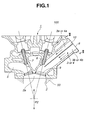
- FIG. 1 there is shown in a sectional manner a cylinder head 1 which is an air intake device 100 of a first embodiment of the present invention.
- a sectional view taken along the line II-II of Fig. 1 is shown in Fig. 2.
- Cylinder head 1 is cast from an aluminum alloy or the like.
- cylinder head 1 is formed with two, that is, first and second intake ports 3 and 4 for each cylinder 2 of a cylinder block 50. Furthermore, cylinder head 1 is formed with two exhaust ports 5 for each cylinder 2. Each of intake and exhaust ports 3, 4 and 5 is provided with an intake or exhaust valve (not shown) that is movably held by a valve guide 6 or 7 installed in cylinder head 1. That is, when pushed down, each intake or exhaust valve opens the corresponding intake or exhaust opening exposed to a combustion chamber 2a defined by cylinder 2 above a piston (not shown).
- two intake ports 3 and 4 are arranged to extend abreast with respect to a direction "P1" of the axis of a crankshaft (not shown) keeping a certain small distance “D” therebetween. That is, two intake ports 3 and 4 are put on an imaginary plane “IP” that extends in parallel with the axis of the crankshaft.
- two intake ports 3 and 4 extend in parallel with each other from upstream ends 8 thereof to which an intake manifold (not shown) is connected to downstream ends 9 thereof which are exposed to combustion chamber 2a. It is to be noted that the parallel arrangement of two intake ports 3 and 4 may be not so accurate.
- partition plate 10 extends across both two intake ports 3 and 4 in such a manner that each intake port 3 or 4 is divided into an upper passage 3a or 4a and a lower passage 3b or 4b by the plate 10.
- partition plate 10 extends from upstream ends 8 of two intake ports 3 and 4 to a position near downstream ends 9 of the same.
- first or second intake port 3 or 4 is divided into an upper passage 3a or 4a and a lower passage 3b or 4b which are arranged at upper and lower portions with respect to a direction "P2" of an axis of the corresponding cylinder 2.
- a tumbling air flow control valve (not shown) that selectively opens and closes lower passages 3b and 4b.
- the tumbling air flow control valve By closing lower passages 3b and 4b by the tumbling air flow control valve thereby causing only upper passages 3a and 4a of two intake ports 3 and 4 to open, the tumbling effect applied to intake air led to the cylinder 2 is increased or strengthened. With this, a higher fuel efficiency is expected by the engine.
- each of first and second intake ports 3 and 4 is oval in cross section with its long axis extending in the direction "P2" of the axis of the corresponding cylinder 2.
- partition plate 10 is located just above an imaginary plane "P3" that includes a center axis 3c of first intake port 3 and a center axis 4c of second intake port 4, so that upper passage 3a or 4a has a smaller sectional area than lower passage 3b or 4b. That is, partition plate 10 is poisoned nearer to upper passages 3a and 4a than lower passages 3b and 4b, as shown.
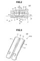
- a sand core unit "SCU” having a partition plate 10 embedded therein is prepared. That is, the sand core unit “SCU” comprises first and second sand cores 11 and 12 that are shaped to correspond to first and second intake ports 3 and 4, and partition plate 10 that has laterally opposed side portions embedded in first and second sand cores 11 and 12.
- Partition plate 10 may be constructed of duralumin having a thickness of about 1 to 2 mm.
- partition plate 10 held by sand cores 11 and 12 has opposed lateral edge parts 14 and 15 and a center narrow part 16 which are exposed to the outside. As is seen from Fig. 2, upon completion of casting, these exposed parts 14, 15 and 16 are embedded in the cast aluminum alloy of the cylinder head 1 produced.
- sand core units "SCU” For practically casting cylinder head 1, given numbers of sand core units "SCU" are set in given positions in a sand mold, and a melted aluminum alloy is poured into cavities of the sand mold. After the aluminum alloy is cooled and thus hardened, the sand mold is broken to expose the product, viz., the cylinder head 1.
- partition plate 10 is supported in cylinder head 1 through three supporting areas of partition plate 10, which are one lateral edge part 14, the other lateral edge part 15 and center narrow part 16.
- the center narrow part 16 is steadily embedded in a partition wall of cylinder head 1 by which two intake ports 3 and 4 are separated.
- the single partition plate 10 is much tightly held by cylinder head 1 as compared with the above-mentioned known case wherein the two partition plates are respectively installed in two intake ports 3 and 4.
- the distance "D" can be much reduced, which induces a compact construction of the air intake device 100.
- upper and lower passages 3a and 3b of first intake port 3 and those 4a and 4b of second intake port 4 are can be defined by only one partition plate 10. This means reduction in number of parts used and simplification of manufacturing cylinder head 1. Furthermore, for the same reason, freedom in layout of partition plate 10 in cylinder head 1 is increased.
- FIG. 4 there is shown a sectional view similar to Fig. 2, but showing an air intake device 200 of a second embodiment of the present invention.
- each of first and second intake ports 23 and 24 has a circular cross section. Furthermore, a partition plate 10A used extends in and along the imaginary plane "P3" that includes a center axis 23c of first intake port 23 and a center axis 24c of second intake port 24.
- P3 the imaginary plane that includes a center axis 23c of first intake port 23 and a center axis 24c of second intake port 24.
- upper and lower passages 23a and 23b of first intake port 23 have the same sectional area and those 24a and 24b of second intake port 24 have the same sectional area.
- FIG. 5 there is shown a sectional view similar to Fig. 2 also, but showing an air intake device 300 of a third embodiment of the present invention.'
- first and second intake ports 33 and 34 have each an oval cross section.
- a partition plate 10B used is bent at its center narrow part 16 to have a generally V-shaped cross section. That is, the center narrow part 16 of partition plate 10B is located on the imaginary plane "P3" that includes a center axis 33c of first intake port 33 and a center axis 34c of second intake port 34.
- laterally opposed portions 17 and 18 of partition plate 10B are inclined relative to the imaginary plane "P3". That is, the portions 17 and 18 are inclined toward upper passages 33a and 34a respectively, so that upper passages 33a and 34a have each a smaller sectional area than lower passages 33b and 34b, like in the above-mentioned first embodiment 100.
Landscapes
- Engineering & Computer Science (AREA)
- Chemical & Material Sciences (AREA)
- Combustion & Propulsion (AREA)
- Mechanical Engineering (AREA)
- General Engineering & Computer Science (AREA)
- Cylinder Crankcases Of Internal Combustion Engines (AREA)
Abstract
Description
- The present invention relates in general to air intake devices of internal combustion engines, and more particularly to the air intake devices of a type that has two intake ports for each cylinder of a cylinder block of the internal combustion engine.
- Laid-open Japanese Patent Application (Tokkai) 2001-193469 shows an air intake device of the above-mentioned type that is constructed to strengthen a tumbling air flow led to the cylinders of the engine. That is, in the air intake device disclosed by the publication, an elongate partition plate is installed in each intake port in a manner to extend along an axis of the intake port defining upper and lower parallel passages therein. The partition plates are integrally installed in the cylinder head upon casting of the cylinder head. Each partition plate has side edges embedded in a cylindrical wall of the intake port.
- However, due to its inherent construction, the air intake device of the publication fails to have a satisfied stoutness with which the partition plate is fixed to the cylinder head. Furthermore, when the measures of the publication are applied to neighboring two intake ports, a difficulty arises in positioning the respective partition plates to the two intake ports. That is, if the two partition plates are arranged to lie on the same imaginary plane, a certain but not small distance should be provided between the two intake ports, which would bring about a bulky construction of the intake device.
- It is therefore an object of the present invention to provide an air intake device of an internal combustion engine, which is free of the above-mentioned drawbacks.
- According to a first aspect of the present invention, there is provided an air intake device of an internal combustion engine, which comprises a cylinder head having therein two intake ports that are adapted to connect to a cylinder of a cylinder block; and a single partition plate that extends across both the two intake ports so that each of the two intake ports is divided into first and second air passages.
- According to a second aspect of the present invention, there is provided an air intake device an internal combustion engine, which comprises a cylinder head having therein two intake portions that are adapted to connect to a cylinder of a cylinder block and two exhaust ports that are adapted to connect to the cylinder; and a single partition plate that extends across both the two intake ports so that each of the two intake ports is divided into upper and lower air passages.
-
- Fig. 1 is a sectional view of a cylinder head of an internal combustion engine, which is an air intake device of a first embodiment of the present invention;
- Fig. 2 is a sectional view taken along the line II-II of Fig. 1;
- Fig. 3 is a perspective view of a sand core unit with a partition plate, that is used when casting the cylinder head;
- Fig. 4 is a sectional view similar to Fig. 2, but showing a second embodiment of the present invention; and
- Fig. 5 is a sectional view also similar to Fig. 2, but showing a third embodiment of the present invention.
-
- In the following, air intake devices embodying the present invention will be described in detail with reference to the accompanying drawings.
- Referring to Fig. 1, there is shown in a sectional manner a
cylinder head 1 which is anair intake device 100 of a first embodiment of the present invention. A sectional view taken along the line II-II of Fig. 1 is shown in Fig. 2. -
Cylinder head 1 is cast from an aluminum alloy or the like. - As is seen from Figs. 1 and 2,
cylinder head 1 is formed with two, that is, first andsecond intake ports cylinder 2 of acylinder block 50. Furthermore,cylinder head 1 is formed with twoexhaust ports 5 for eachcylinder 2. Each of intake andexhaust ports valve guide cylinder head 1. That is, when pushed down, each intake or exhaust valve opens the corresponding intake or exhaust opening exposed to acombustion chamber 2a defined bycylinder 2 above a piston (not shown). - As is seen from Fig. 2, two
intake ports intake ports - As is seen from Fig. 1, two
intake ports upstream ends 8 thereof to which an intake manifold (not shown) is connected todownstream ends 9 thereof which are exposed tocombustion chamber 2a. It is to be noted that the parallel arrangement of twointake ports - As is seen from Fig. 2, a
single partition plate 10 of metal extends across both twointake ports intake port upper passage lower passage plate 10. As is seen from Fig. 1,partition plate 10 extends fromupstream ends 8 of twointake ports downstream ends 9 of the same. - That is, as is seen from Figs. 1 and 2, with provision of
partition plate 10, first orsecond intake port upper passage lower passage corresponding cylinder 2. - Although not shown in the drawings, at upstream portions of two
intake ports lower passages lower passages upper passages intake ports cylinder 2 is increased or strengthened. With this, a higher fuel efficiency is expected by the engine. - As is seen from Fig. 2, in this first embodiment, each of first and
second intake ports corresponding cylinder 2. Furthermore, in this first embodiment,partition plate 10 is located just above an imaginary plane "P3" that includes acenter axis 3c offirst intake port 3 and acenter axis 4c ofsecond intake port 4, so thatupper passage lower passage partition plate 10 is poisoned nearer toupper passages lower passages - In order to produce the above-mentioned
cylinder head 1 to which the first embodiment of the present invention is applied, the following casting method is employed. - That is, as is shown in Fig. 3, a sand core unit "SCU" having a
partition plate 10 embedded therein is prepared. That is, the sand core unit "SCU" comprises first andsecond sand cores second intake ports partition plate 10 that has laterally opposed side portions embedded in first andsecond sand cores Partition plate 10 may be constructed of duralumin having a thickness of about 1 to 2 mm. As shown,partition plate 10 held bysand cores lateral edge parts narrow part 16 which are exposed to the outside. As is seen from Fig. 2, upon completion of casting, these exposedparts cylinder head 1 produced. - For practically casting
cylinder head 1, given numbers of sand core units "SCU" are set in given positions in a sand mold, and a melted aluminum alloy is poured into cavities of the sand mold. After the aluminum alloy is cooled and thus hardened, the sand mold is broken to expose the product, viz., thecylinder head 1. - In the following, advantages of the
air intake device 100 with respect to the known air intake device disclosed by the above-mentioned Japanese publication will be described. - First, as is seen from Fig. 2,
partition plate 10 is supported incylinder head 1 through three supporting areas ofpartition plate 10, which are onelateral edge part 14, the otherlateral edge part 15 and centernarrow part 16. As is understood from the drawing, the centernarrow part 16 is steadily embedded in a partition wall ofcylinder head 1 by which twointake ports single partition plate 10 is much tightly held bycylinder head 1 as compared with the above-mentioned known case wherein the two partition plates are respectively installed in twointake ports air intake device 100. - Second, upper and
lower passages first intake port 3 and those 4a and 4b ofsecond intake port 4 are can be defined by only onepartition plate 10. This means reduction in number of parts used and simplification ofmanufacturing cylinder head 1. Furthermore, for the same reason, freedom in layout ofpartition plate 10 incylinder head 1 is increased. - Referring to Fig. 4, there is shown a sectional view similar to Fig. 2, but showing an
air intake device 200 of a second embodiment of the present invention. - In this
embodiment 200, each of first andsecond intake ports partition plate 10A used extends in and along the imaginary plane "P3" that includes acenter axis 23c offirst intake port 23 and acenter axis 24c ofsecond intake port 24. Thus, in thisembodiment 200, upper andlower passages first intake port 23 have the same sectional area and those 24a and 24b ofsecond intake port 24 have the same sectional area. - Referring to Fig. 5, there is shown a sectional view similar to Fig. 2 also, but showing an
air intake device 300 of a third embodiment of the present invention.' - In this
embodiment 300, similar to the above-mentionedfirst embodiment 100, first andsecond intake ports partition plate 10B used is bent at its centernarrow part 16 to have a generally V-shaped cross section. That is, the centernarrow part 16 ofpartition plate 10B is located on the imaginary plane "P3" that includes acenter axis 33c offirst intake port 33 and acenter axis 34c ofsecond intake port 34. Furthermore, as shown, laterally opposedportions partition plate 10B are inclined relative to the imaginary plane "P3". That is, theportions upper passages upper passages lower passages first embodiment 100. - The entire contents of Japanese Patent Application 2002-34846 (filed February 13, 2002) are incorporated herein by reference.
- Although the invention has been described above with reference to the embodiments of the invention, the invention is not limited to such embodiments as described above. Various modifications and variations of such embodiments may be carried out by those skilled in the art, in light of the above description.
Claims (7)
- An air intake device of an internal combustion engine, comprising:a cylinder head (1) having therein two intake ports (3,4), (23, 24), (33, 34) that are adapted to connect to a cylinder (2) of a cylinder block (50); anda single partition plate (10, 10A, 10B) that extends across both the two intake ports so that each of the two intake ports is divided into first and second air passages [(3a, 4a), (3b,4b)], [(23a, 24a), (23b, 24b)], [(33a, 34a), (33b, 34b)].
- An air intake device as claimed in Claim 1, in which the partition plate extends on a plane that is spaced away from an imaginary plane (P3) that includes center axes (3c, 4c), (23c, 24c), (33c, 34c) of the two intake ports.
- An air intake device as claimed in Claim 1 or 2, in which the partition plate is bent to have a V-shaped cross section, so that portions of the partition plate that are respectively exposed to the two intake ports are inclined relative to an imaginary plane (P3) that includes center axes (3c, 4c), (23c, 24c), (33c, 34c) of the two intake ports.
- An air intake device as claimed in Claim 1, 2 or 3, in which the two intake ports have each one of oval and circular cross sections.
- An air intake device as claimed in Claim 1, 2, 3 or 4, in which the partition plate is integrally installed in the cylinder head upon casting of the cylinder head.
- An air intake device as claimed in Claim 1, 2, 3, 4 or 5 in which the partition plate has a thickness of approximately 1 mm to approximately 2 mm.
- An air intake device an internal combustion engine, comprising:a cylinder head (1) having therein two intake ports (3,4), (23, 24), (33, 34) that are adapted to connect to a cylinder (2) of a cylinder block (50) and two exhaust ports (5) that are adapted to connect to the cylinder (2); anda single partition plate (10, 10A, 10B) that extends across both the two intake ports so that each of the two intake ports is divided into upper and lower air passages [(3a, 4a), (3b,4b)], [(23a, 24a), (23b, 24b)], [(33a, 34a), (33b, 34b)].
Applications Claiming Priority (2)
| Application Number | Priority Date | Filing Date | Title |
|---|---|---|---|
| JP2002034846 | 2002-02-13 | ||
| JP2002034846A JP3695401B2 (en) | 2002-02-13 | 2002-02-13 | Intake device for internal combustion engine |
Publications (3)
| Publication Number | Publication Date |
|---|---|
| EP1336750A2 true EP1336750A2 (en) | 2003-08-20 |
| EP1336750A3 EP1336750A3 (en) | 2005-04-20 |
| EP1336750B1 EP1336750B1 (en) | 2008-10-29 |
Family
ID=27621393
Family Applications (1)
| Application Number | Title | Priority Date | Filing Date |
|---|---|---|---|
| EP03002663A Expired - Lifetime EP1336750B1 (en) | 2002-02-13 | 2003-02-11 | Air intake device of internal combustion engine |
Country Status (4)
| Country | Link |
|---|---|
| US (1) | US7111607B2 (en) |
| EP (1) | EP1336750B1 (en) |
| JP (1) | JP3695401B2 (en) |
| DE (1) | DE60324346D1 (en) |
Cited By (6)
| Publication number | Priority date | Publication date | Assignee | Title |
|---|---|---|---|---|
| EP1525935A1 (en) * | 2003-10-20 | 2005-04-27 | Nissan Motor Co., Ltd. | Cast-in object plate member, partition plate for intake port, intake-port forming sand core and cylinder head |
| EP1525934A1 (en) * | 2003-10-20 | 2005-04-27 | Nissan Motor Co., Ltd. | Partition plate for an intake port of an internal combustion engine, sand core, cylinder head and its casting method |
| EP1548263A1 (en) * | 2003-10-20 | 2005-06-29 | Nissan Motor Co., Ltd. | Partition plate for intake port, sand core for forming intake port, and cylinder head |
| EP1555422A1 (en) * | 2004-01-15 | 2005-07-20 | Renault s.a.s. | Intake device for internal combustion engine with spark ignition |
| EP3255270A1 (en) * | 2016-06-09 | 2017-12-13 | Renault s.a.s | Element for diverting a fluid flowing in a fluid duct of a cylinder head |
| WO2018024900A1 (en) * | 2016-08-04 | 2018-02-08 | Serlidakis Andreas | System for reducing gas pollutants and fuel consumption in internal combustion engines |
Families Citing this family (9)
| Publication number | Priority date | Publication date | Assignee | Title |
|---|---|---|---|---|
| KR100580493B1 (en) * | 2004-04-23 | 2006-05-16 | 현대자동차주식회사 | Structure of Intake / Exhaust Port Forming Core |
| JP4557659B2 (en) * | 2004-09-30 | 2010-10-06 | 株式会社新エィシーイー | Cylinder head casting core with variable swirl intake system |
| US7565894B2 (en) * | 2005-09-12 | 2009-07-28 | Hitachi, Ltd. | Fuel injection apparatus for and method of internal combustion engine, and fuel injection valve |
| JP2007297952A (en) * | 2006-04-28 | 2007-11-15 | Toyota Motor Corp | Intake device for internal combustion engine |
| CN104114832B (en) * | 2012-03-30 | 2016-09-07 | 本田技研工业株式会社 | Aspirator for internal combustion engines |
| US9464605B2 (en) | 2013-08-24 | 2016-10-11 | Lonn M. Peterson | Quad flow torque enhancement flow divider causing improved fuel/air transfer |
| EP3428433B1 (en) * | 2016-03-09 | 2020-02-19 | Honda Motor Co., Ltd. | Internal combustion engine intake structure |
| US10907573B2 (en) | 2016-10-21 | 2021-02-02 | Honda Motor Co., Ltd. | Thermally insulated insert member and engine having same |
| ES2957265T3 (en) | 2017-06-19 | 2024-01-16 | Nira Dynamics Ab | Vehicle wheel monitoring |
Citations (2)
| Publication number | Priority date | Publication date | Assignee | Title |
|---|---|---|---|---|
| JP2001193469A (en) | 1999-12-16 | 2001-07-17 | Fev Motorentechnik Gmbh & Co Kg | Piston internal combustion engine with split gas intake passage |
| JP2002034846A (en) | 2000-07-31 | 2002-02-05 | Matsushita Electric Ind Co Ltd | Hand drying equipment |
Family Cites Families (9)
| Publication number | Priority date | Publication date | Assignee | Title |
|---|---|---|---|---|
| JPS62228622A (en) * | 1986-03-31 | 1987-10-07 | Yamaha Motor Co Ltd | Suction device for engine |
| DE3711859C2 (en) * | 1986-04-19 | 2003-04-17 | Volkswagen Ag | Multi-cylinder reciprocating internal combustion engine |
| US5273014A (en) * | 1991-06-11 | 1993-12-28 | Mazda Motor Corporation | Intake system for engine |
| US5553590A (en) * | 1992-07-14 | 1996-09-10 | Yamaha Hatsudoki Kabushiki Kaisha | Intake control valve |
| DE9319545U1 (en) * | 1993-12-20 | 1995-04-20 | FEV Motorentechnik GmbH & Co. KG, 52078 Aachen | Spark-ignited piston engine with direction-changing inflow of the fuel-air mixture |
| JP3308754B2 (en) * | 1995-02-15 | 2002-07-29 | ヤマハ発動機株式会社 | Engine exhaust recirculation system |
| GB2300225A (en) * | 1995-04-29 | 1996-10-30 | Ford Motor Co | I.c.engine charge tumble intake system |
| US5718198A (en) * | 1997-01-16 | 1998-02-17 | Ford Global Technologies, Inc. | Slide throttle valve for an engine intake system |
| JP3451589B2 (en) * | 1997-03-28 | 2003-09-29 | 有限会社日高エンジニアリング | Intake device for internal combustion engine |
-
2002
- 2002-02-13 JP JP2002034846A patent/JP3695401B2/en not_active Expired - Fee Related
-
2003
- 2003-01-27 US US10/351,398 patent/US7111607B2/en not_active Expired - Fee Related
- 2003-02-11 EP EP03002663A patent/EP1336750B1/en not_active Expired - Lifetime
- 2003-02-11 DE DE60324346T patent/DE60324346D1/en not_active Expired - Lifetime
Patent Citations (2)
| Publication number | Priority date | Publication date | Assignee | Title |
|---|---|---|---|---|
| JP2001193469A (en) | 1999-12-16 | 2001-07-17 | Fev Motorentechnik Gmbh & Co Kg | Piston internal combustion engine with split gas intake passage |
| JP2002034846A (en) | 2000-07-31 | 2002-02-05 | Matsushita Electric Ind Co Ltd | Hand drying equipment |
Cited By (9)
| Publication number | Priority date | Publication date | Assignee | Title |
|---|---|---|---|---|
| EP1525935A1 (en) * | 2003-10-20 | 2005-04-27 | Nissan Motor Co., Ltd. | Cast-in object plate member, partition plate for intake port, intake-port forming sand core and cylinder head |
| EP1525934A1 (en) * | 2003-10-20 | 2005-04-27 | Nissan Motor Co., Ltd. | Partition plate for an intake port of an internal combustion engine, sand core, cylinder head and its casting method |
| EP1548263A1 (en) * | 2003-10-20 | 2005-06-29 | Nissan Motor Co., Ltd. | Partition plate for intake port, sand core for forming intake port, and cylinder head |
| US7032559B2 (en) | 2003-10-20 | 2006-04-25 | Nissan Motor Co., Ltd. | Cast-in object plate member, partition plate for intake port, intake-port forming sand core and cylinder head |
| US7032560B2 (en) | 2003-10-20 | 2006-04-25 | Nissan Motor Co., Ltd. | Partition plate for intake port, sand core for forming intake port, and cylinder head |
| US7100560B2 (en) | 2003-10-20 | 2006-09-05 | Nissan Motor Co., Ltd. | Partition plate for intake port, intake port molding sand core and cylinder head |
| EP1555422A1 (en) * | 2004-01-15 | 2005-07-20 | Renault s.a.s. | Intake device for internal combustion engine with spark ignition |
| EP3255270A1 (en) * | 2016-06-09 | 2017-12-13 | Renault s.a.s | Element for diverting a fluid flowing in a fluid duct of a cylinder head |
| WO2018024900A1 (en) * | 2016-08-04 | 2018-02-08 | Serlidakis Andreas | System for reducing gas pollutants and fuel consumption in internal combustion engines |
Also Published As
| Publication number | Publication date |
|---|---|
| EP1336750B1 (en) | 2008-10-29 |
| EP1336750A3 (en) | 2005-04-20 |
| US7111607B2 (en) | 2006-09-26 |
| US20030150431A1 (en) | 2003-08-14 |
| JP3695401B2 (en) | 2005-09-14 |
| JP2003239750A (en) | 2003-08-27 |
| DE60324346D1 (en) | 2008-12-11 |
Similar Documents
| Publication | Publication Date | Title |
|---|---|---|
| US7111607B2 (en) | Air intake device of internal combustion engine | |
| US7802555B2 (en) | Intake control device for an engine | |
| US7849683B2 (en) | Multiple-cylinder internal combustion engine having cylinder head provided with centralized exhaust passageway | |
| KR20090028817A (en) | An internal combustion engine | |
| JP4020059B2 (en) | Intake device for internal combustion engine | |
| JP2017190674A (en) | Water jacket structure of cylinder head | |
| CN101631948B (en) | Intake manifold for multi-cylinder internal combustion engine | |
| JP3569636B2 (en) | Cylinder head structure of multi-cylinder engine | |
| WO2011136088A1 (en) | Exhaust manifold | |
| JP2511862Y2 (en) | Cylinder head cover of internal combustion engine | |
| JP4652303B2 (en) | Multi-cylinder internal combustion engine with exhaust gas recirculation device | |
| JP3417116B2 (en) | Internal combustion engine with rocker cover integrated with intake manifold | |
| US6155228A (en) | Multicylinder four-stroke internal combustion engine | |
| JP3562031B2 (en) | Rocker cover integrated with intake manifold for internal combustion engine | |
| EP0984149B1 (en) | Cylinder head structure in internal combustion engine | |
| JP3500753B2 (en) | Internal combustion engine with rocker cover integrated with intake manifold | |
| JPH08193546A (en) | Multi-cylinder engine intake system | |
| JP2008075507A (en) | Water-cooled multi-cylinder engine | |
| JP2004052546A (en) | Multi-cylinder engine | |
| JPS62282746A (en) | Expendable pattern for casting cylinder head for internal combustion engine | |
| JP4795905B2 (en) | Water-cooled engine | |
| JP3991630B2 (en) | V-type engine intake system | |
| EP1081351A3 (en) | Air intake system for internal combustion engine | |
| JPH0281919A (en) | Head cooling system for multi-cylinder air-cooled engines | |
| JP2003097242A (en) | Intake manifold for a multi-cylinder internal combustion engine |
Legal Events
| Date | Code | Title | Description |
|---|---|---|---|
| PUAI | Public reference made under article 153(3) epc to a published international application that has entered the european phase |
Free format text: ORIGINAL CODE: 0009012 |
|
| 17P | Request for examination filed |
Effective date: 20030211 |
|
| AK | Designated contracting states |
Designated state(s): AT BE BG CH CY CZ DE DK EE ES FI FR GB GR HU IE IT LI LU MC NL PT SE SI SK TR |
|
| AX | Request for extension of the european patent |
Extension state: AL LT LV MK RO |
|
| PUAL | Search report despatched |
Free format text: ORIGINAL CODE: 0009013 |
|
| AK | Designated contracting states |
Kind code of ref document: A3 Designated state(s): AT BE BG CH CY CZ DE DK EE ES FI FR GB GR HU IE IT LI LU MC NL PT SE SI SK TR |
|
| AX | Request for extension of the european patent |
Extension state: AL LT LV MK RO |
|
| RIC1 | Information provided on ipc code assigned before grant |
Ipc: 7F 02B 31/08 B Ipc: 7F 02M 35/108 A Ipc: 7F 02F 1/42 B |
|
| AKX | Designation fees paid |
Designated state(s): DE FR GB |
|
| 17Q | First examination report despatched |
Effective date: 20051103 |
|
| GRAP | Despatch of communication of intention to grant a patent |
Free format text: ORIGINAL CODE: EPIDOSNIGR1 |
|
| RIN1 | Information on inventor provided before grant (corrected) |
Inventor name: OOTA, HAJIME |
|
| GRAS | Grant fee paid |
Free format text: ORIGINAL CODE: EPIDOSNIGR3 |
|
| GRAA | (expected) grant |
Free format text: ORIGINAL CODE: 0009210 |
|
| AK | Designated contracting states |
Kind code of ref document: B1 Designated state(s): DE FR GB |
|
| REG | Reference to a national code |
Ref country code: GB Ref legal event code: FG4D |
|
| REF | Corresponds to: |
Ref document number: 60324346 Country of ref document: DE Date of ref document: 20081211 Kind code of ref document: P |
|
| PLBE | No opposition filed within time limit |
Free format text: ORIGINAL CODE: 0009261 |
|
| STAA | Information on the status of an ep patent application or granted ep patent |
Free format text: STATUS: NO OPPOSITION FILED WITHIN TIME LIMIT |
|
| 26N | No opposition filed |
Effective date: 20090730 |
|
| PGFP | Annual fee paid to national office [announced via postgrant information from national office to epo] |
Ref country code: FR Payment date: 20140211 Year of fee payment: 12 |
|
| PGFP | Annual fee paid to national office [announced via postgrant information from national office to epo] |
Ref country code: GB Payment date: 20140206 Year of fee payment: 12 |
|
| PGFP | Annual fee paid to national office [announced via postgrant information from national office to epo] |
Ref country code: DE Payment date: 20140417 Year of fee payment: 12 |
|
| REG | Reference to a national code |
Ref country code: DE Ref legal event code: R119 Ref document number: 60324346 Country of ref document: DE |
|
| GBPC | Gb: european patent ceased through non-payment of renewal fee |
Effective date: 20150211 |
|
| REG | Reference to a national code |
Ref country code: FR Ref legal event code: ST Effective date: 20151030 |
|
| PG25 | Lapsed in a contracting state [announced via postgrant information from national office to epo] |
Ref country code: GB Free format text: LAPSE BECAUSE OF NON-PAYMENT OF DUE FEES Effective date: 20150211 Ref country code: DE Free format text: LAPSE BECAUSE OF NON-PAYMENT OF DUE FEES Effective date: 20150901 |
|
| PG25 | Lapsed in a contracting state [announced via postgrant information from national office to epo] |
Ref country code: FR Free format text: LAPSE BECAUSE OF NON-PAYMENT OF DUE FEES Effective date: 20150302 |