EP1335528B1 - Using subnet relations to perform handover in a wireless communication device - Google Patents
Using subnet relations to perform handover in a wireless communication device Download PDFInfo
- Publication number
- EP1335528B1 EP1335528B1 EP02014837A EP02014837A EP1335528B1 EP 1335528 B1 EP1335528 B1 EP 1335528B1 EP 02014837 A EP02014837 A EP 02014837A EP 02014837 A EP02014837 A EP 02014837A EP 1335528 B1 EP1335528 B1 EP 1335528B1
- Authority
- EP
- European Patent Office
- Prior art keywords
- subnet
- wireless communication
- communication device
- handoff
- subnets
- Prior art date
- Legal status (The legal status is an assumption and is not a legal conclusion. Google has not performed a legal analysis and makes no representation as to the accuracy of the status listed.)
- Expired - Lifetime
Links
Images


Classifications
-
- H—ELECTRICITY
- H04—ELECTRIC COMMUNICATION TECHNIQUE
- H04W—WIRELESS COMMUNICATION NETWORKS
- H04W48/00—Access restriction; Network selection; Access point selection
- H04W48/16—Discovering, processing access restriction or access information
-
- H—ELECTRICITY
- H04—ELECTRIC COMMUNICATION TECHNIQUE
- H04W—WIRELESS COMMUNICATION NETWORKS
- H04W36/00—Hand-off or reselection arrangements
-
- H—ELECTRICITY
- H04—ELECTRIC COMMUNICATION TECHNIQUE
- H04W—WIRELESS COMMUNICATION NETWORKS
- H04W52/00—Power management, e.g. TPC [Transmission Power Control], power saving or power classes
- H04W52/02—Power saving arrangements
- H04W52/0209—Power saving arrangements in terminal devices
- H04W52/0261—Power saving arrangements in terminal devices managing power supply demand, e.g. depending on battery level
- H04W52/0274—Power saving arrangements in terminal devices managing power supply demand, e.g. depending on battery level by switching on or off the equipment or parts thereof
-
- H—ELECTRICITY
- H04—ELECTRIC COMMUNICATION TECHNIQUE
- H04W—WIRELESS COMMUNICATION NETWORKS
- H04W88/00—Devices specially adapted for wireless communication networks, e.g. terminals, base stations or access point devices
- H04W88/02—Terminal devices
- H04W88/06—Terminal devices adapted for operation in multiple networks or having at least two operational modes, e.g. multi-mode terminals
-
- Y—GENERAL TAGGING OF NEW TECHNOLOGICAL DEVELOPMENTS; GENERAL TAGGING OF CROSS-SECTIONAL TECHNOLOGIES SPANNING OVER SEVERAL SECTIONS OF THE IPC; TECHNICAL SUBJECTS COVERED BY FORMER USPC CROSS-REFERENCE ART COLLECTIONS [XRACs] AND DIGESTS
- Y02—TECHNOLOGIES OR APPLICATIONS FOR MITIGATION OR ADAPTATION AGAINST CLIMATE CHANGE
- Y02D—CLIMATE CHANGE MITIGATION TECHNOLOGIES IN INFORMATION AND COMMUNICATION TECHNOLOGIES [ICT], I.E. INFORMATION AND COMMUNICATION TECHNOLOGIES AIMING AT THE REDUCTION OF THEIR OWN ENERGY USE
- Y02D30/00—Reducing energy consumption in communication networks
- Y02D30/70—Reducing energy consumption in communication networks in wireless communication networks
Definitions
- the present invention relates generally to wireless communication systems and, more particularly, to a system and method using subnet relations to conserve power in a wireless communication system.
- WO 01/72076 A1 there is described a handover in a multi-bearer-type network, wherein a network element supporting mobility of mobile nodes and the mobile node have a handover logic for handing over a mobile node to a neighbouring network element.
- the handover logic is adapted to provide continuous service for a mobile node after it has moved to the support area of the neighbouring network element and before it has re-registered with its home agent.
- the mobile radio communication terminal includes a feeding controller with a feeding control table which stores the on/off state of the power to each circuit in correspondence to all operation modes of the apparatus.
- a mobile wireless communications system includes base stations of a first type operating according to a first air interface, and base stations of a second type operating according to a second air interface.
- a communications link is established over the first air interface between the mobile station and the first base station.
- Data is received from the mobile station responsive to a signal received by the mobile station over the second air interface from the second base station, substantially without breaking the communications link with the first base station.
- the mobile station is handed over from the first base station to the second base station responsive to the data received therefrom.
- WO 97/32445 there is described a method and apparatus for adaptively reconfiguring a neighbouring cell list.
- data associated with the selected cell and each of a plurality of neighbouring base stations is collected.
- the collected data includes data includes data on events indicative of the quality of handoffs from the selected cell to each of the neighbouring base stations.
- the collected data also includes signal level measurements made on measurement channels of the neighbouring base stations.
- a plurality of quality values, each associated with the selected cell and one of the neighbouring cells, are then determined from the collected data.
- a neighbour cell list is then generated for the selected cell by determining the highest quality values, and placing the handoff measurement channels of the neighbouring cells associated with the highest quality values in the neighbour cell list.
- WO 96/36190 there is described a method for generating a handoff candidate list.
- the handoff candidate list is generated for a source sector by eliminating from a list of potential handoff candidates any sectors having an interference parameter exceeding a threshold value.
- the list is further reduced by determining a handoff radius and eliminating any candidate sectors that fall outside the handoff radius. Candidate sectors that do not have overlapping coverage areas are also eliminated. In addition, candidate sectors having a relative angle of sight to the source sector that exceeds a maximum angle are also eliminated. Finally, the list is reduced to a preset number of candidates dependent upon the interference parameter.
- a handover candidate list is provided to the remote unit.
- the list comprises a set of neighbouring base stations that are capable of supporting the service requirements of the remote unit and does not include any neighbouring base station that are incapable of supporting the current service required by the remote unit.
- a typical portable device has an acceptable weight range between 4-12 oz. for most handheld applications based on human factor studies.
- the well-known nickel cadmium (NiCd) batteries, lithium-ion (Li-ion) batteries, and nickel metal hydride (NiMH) batteries are popular; however, multiple access systems need more powerful batteries and other technologies to reduce battery drain.
- NiCd nickel cadmium
- Li-ion lithium-ion
- NiMH nickel metal hydride
- One way to reduce energy consumption is to use and develop components that consume less power. Another way is to use components that can enter low power modes by temporarily reducing their speed or functionality. For this scheme, one strategy is to compress TCP/IP headers, which reduces their size by an order of magnitude, thereby reducing the wireless communication activity of a mobile client. Another way is to reduce the data transmission rate or stop data transmission altogether when the channel is bad, i.e., when the probability of dropped packets is high, so that less transmission time is wasted sending packets that will be dropped.
- Another method is to use a medium access control protocol that dictates in advance when each wireless device may receive data.
- another strategy is to have servers or proxies use information about mobile client characteristics and data semantics to provide mobile clients with versions of data with reduced fidelity and smaller size, which reduces the amount of energy mobile clients must expend to receive the data.
- a data server might convert a color picture to a black-and-white version before sending it to a mobile client.
- it is necessary to design applications that avoid unnecessary communication, especially in the expensive transmit direction.
- each wireless communication device has at least one network interface.
- the term network interface should be broadly construed to include any type of device, together with its associated software, that may be used to connect a wireless communication device to a network.
- Remote terminals and personal digital assistants can be equipped with several different types of network interfaces that are used to communicate with various types of wireless communication networks.
- the present invention allows the wireless communication device to place network interfaces that are not going to be used, which is based on the location of the wireless communication device and current available access networks, in a power-saving mode. The power-saving mode will reduce the power that is provided to a particular network interface or disable the network interface altogether.
- a wireless communication network includes a plurality of subnets. Each subnet is preferentially located within a much larger access network that includes a plurality of subnets.
- a subnet relation database is used to determine what subnets the wireless communication device can access from a current subnet. Based on the information contained in the subnet relation database, network interfaces on wireless communication devices that cannot be used by the wireless communication device are placed in a power-saving mode or in a non-active mode.
- the subnet relation database is preferentially located on a virtual operator server that is connected with a mobility agent server.
- Each subnet is connected to the mobility agent server that keeps track of the wireless communication device and connects the virtual operator server to the subnets, which, in turn, connects the virtual operator server to the wireless communication devices.
- the mobility agent server is operable to detect when a wireless communication device performs a handoff from one subnet to another subnet. The mobility agent server notifies the virtual operator server when a respective wireless communication device performs a handoff to another subnet.
- the virtual operator looks to a subnet relation database to determine what other subnets the wireless communication device can handoff to from its current subnet.
- the virtual operator server is aware of what type of network interface the wireless communication device needs to communicate with each respective subnet within the wireless communication system.
- a message is sent to the wireless communication device from the virtual operator server that informs the wireless communication device, which network interfaces may be placed in the power-saving mode. If the user of the wireless communication device has an automatic configuration option, the wireless communication device will automatically place each network interface that cannot be used in a power-saving mode.
- a binding update message is used that informs the virtual operator server of IP address changes. To track the binding update message, the subnet relation database is created.
- the subnet relation database includes connectivity information for each subnet in the plurality of subnets.
- Connectivity information refers to information that identifies each subnet that the wireless communication device can perform a handoff with the subnet in which they are currently operating. For example, if a wireless communication device is in subnet A, the virtual operator server knows that the wireless communication device can only handoff to, for instance, subnets D, E and F because the subnet relation database contains information that indicates this fact. As such, if the wireless communication device includes a network interface that only works with subnet C, the wireless communication device can place this network interface in a power-saving mode or switch off. This is because there is no need to have it operating since the wireless communication device cannot possibly access subnet C from its current location.
- Another embodiment of the present invention discloses a method of monitoring subnet relations in a wireless communication system.
- a wireless communication device is provided that is located in a first subnet.
- a handoff detection application is used to detect when the wireless communication device executes a handoff to a second subnet within the wireless communication system.
- a subnet relation is created between the first subnet and the second subnet because the second subnet is within radio range of the first subnet and the wireless communication device can perform a handoff to the second subnet.
- the subnet relation is created, it is stored in a subnet relation database.
- a mobility agent server is notified when the wireless communication device makes the handoff.
- a mobility agent notifies a virtual operator of the handoff to the second subnet.
- the virtual operator server is used to create and store the subnet relation.
- the subnet relation is stored in a subnet relation database located on the virtual operator server.
- the present preferred embodiment has a wireless communication device that includes at least one network interface.
- the network interfaces connect the wireless communication device to a plurality of subnets.
- At least one mobility agent server is connected to predetermined subnets within the plurality of subnets.
- a virtual operator server is connected to each mobility agent server.
- a subnet relation database is located on the virtual operator server. During operation, the virtual operator server is operable to use the subnet relation database to determine which network interfaces on the wireless communication device should be active or powered up when the wireless communication device is located in a specific subnet.
- Yet another preferred embodiment of the present invention discloses a method for managing subnet relations in a wireless communication device that has at least one network interface.
- a plurality of access networks is provided that include at least one subnet.
- the wireless communication device is connected to a respective subnet.
- the next step in the preferred method is to determine to which subnets the wireless communication device is capable of performing a handoff from the respective subnet it currently occupies.
- Each network interface that cannot be used by any of the surrounding subnets is then placed in a power-saving mode.
- a preferred embodiment of the present invention includes a wireless communication network 10 that has an IP subnet 12.
- a mobility agent server creates the IP subnet 12.
- the IP subnet 12 includes at least one wireless communication device 14 that is capable of being connected to a plurality of access networks 16, 18, 20.
- Each access network 16, 18, 20 preferentially includes a server 22, 24, 26 that is connected to an Internet connection 28.
- the servers 22, 24, 26 are connected to base stations that communicate with the wireless communication devices 14.
- Each respective server 22, 24, 26 is also connected to a virtual operator server 30 by means of the Internet connection 28.
- the mobility agent server within each access network 16, 18, 20 is connected to the servers 22, 24, 26 as well.
- a homogeneous access network 40 would comprise a wireless communication system that includes a plurality of access points 42. Each access point 42 of the access network 40 is connected to the MAS 44. Although not illustrated, each access point 42 is connected to the server by way of the MAS 44. As further illustrated in FIG. 2 , each access point 42 has a predefined coverage area that is represented by area 46.
- a second MAS 50 is connected to a heterogeneous access network 52.
- a heterogeneous access network 52 is made up of a plurality of access networks 54, 56, 58.
- each respective access network 54, 56, 58 represents a different or diverse type of network from the other and also includes at least one access point 60, 62, 64.
- the second MAS 50 is connected to each access point 60, 62, 64, which operate in different access networks 54, 56, 58.
- the access networks 54, 56, 58 can be wireless or wired access networks.
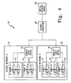
- FIG. 4 which sets forth a general diagram of a preferred wireless IP network 10 used in the present invention
- location information is important to manage users in wireless IP networks 10.
- the virtual operator server 30 establishes a subnet relation map or database that is based on handoff experience.
- the virtual operator server 30 tracks IP subnet changes when wireless communication devices 14 move from one subnet to another subnet. This movement is generally referred to as a handoff.
- Subnets are generally assumed to be close to each other when the wireless communication devices 14 can perform a handoff.
- a first access network 70 includes a plurality of IP subnets 72 that are connected to a first MAS 74.
- the second access network 76 also includes a plurality of IP subnets 72 that are connected to a second MAS 78.
- each MAS 74, 78 is preferentially connected to an Internet connection 28 that, in turn, connects each MAS 74, 78 with the virtual operator server 30.
- a first user 80 has a global address assigned by the virtual operator server 30.
- the first user 80 also has a connection (arrow 82) to the first MAS 74, which is located in the first access network 70.
- a second user 84 also has a global address assigned by the virtual operator server 30 and connects (arrow 86) to the second MAS 78, which is also located in the first access network 70.
- the first user 80 performs a handoff from the first MAS 74 to a third MAS 88
- the first user 80 will register its global address to the third MAS 88 (see the arrow 90).
- the third MAS 88 is located in the second access network 76.
- the third MAS 88 will update the MAS-global address mapping of the first user 80 at the virtual operator server 30 (arrow 92).
- the fourth MAS 94 also updates the MAS-global address mapping at the virtual operator server 30 (arrow 98). If the first user 80 performs another handoff from the third MAS 88 to the second MAS 78 (arrow 100), then the MAS-global address mapping will be updated at the virtual operator server 30 (arrow 102).
- the virtual operator server 30 keeps track of a plurality wireless communication devices 14 as they handoff from MAS to MAS. Generally speaking, if one MAS is too far from another MAS, it would be impossible for the user of a wireless communication device 14 to handoff to the distant MAS. Consequently, the ability to handoff usually indicates that each IP subnet is located close to each other so that there is some overlap in coverage areas. As such, the virtual operator server 30 is capable of mapping out the respective interconnections amongst subnets within a full-scale wireless IP network 10. As such, the virtual operator server knows what subnets are located in a respective geographic location that are capable of being accessed by wireless communication devices 14.
- the virtual operator server 30 tracks subnet relations by handoff experience and creates a subnet relation map 110.
- the subnet relation map 110 shows that the first MAS 74 has a subnet relation 112 with the third MAS 88, because the first user 80 is capable of handing off from the first MAS 74 to the third MAS 88. Furthermore, the first user 80 is capable of handing off from the third MAS 88 to the second MAS 78, thereby creating another subnet relation 114.
- Subnet relation 116 is created by the fact that the second user 84 is capable of handing off from the second MAS 78 to the fourth MAS 94.
- the subnet relation map 110 illustrated in FIG. 6 represents only a small piece of the total number of access networks that would be connected to the virtual operator server 30. As such, the subnet relation map 110 should be viewed in an illustrative sense and not as a limitation of the present invention. From this subnet relation map 110, it is illustrated that the first MAS 74 has the ability to handoff to the third MAS 88. In turn, the third MAS 88 has the ability to handoff to the first MAS 74, the second MAS 78, the fourth MAS 94, a fifth MAS_A 118 and a sixth MAS_B 120.
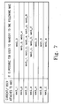
- FIG. 7 illustrates all of the subnet relations that are possible for each MAS in the example set forth in FIG. 6 .
- knowing this information gives the virtual operator server 30 the ability to assist the wireless communication device 14 in its efforts to reduce power consumption.
- the wireless communication device 14 could shut down the network interface that is associated with a particular type of subnet or set the network interface into a sleep mode. Either of these options allows the wireless communication device 14 to conserve energy by reducing or eliminating power consumption that is associated with network interfaces.
- FIG. 8 illustrates a preferred subnet relationship application 120 that creates the subnet relation map 110, which is located on the virtual operator server 30.
- a handoff is detected by a handoff detection application 122.
- the handoff detection application 122 preferentially identifies subnet handoffs, which means that the IP address assigned by the MAS has changed because the wireless communication device 14 has moved from a current MAS territory to another MAS territory.
- this detection includes that this IP address change is triggered by the handoff.
- the preferred embodiment of the present invention also determines whether or not the wireless communication device 14 initiated the handoff or some other source. Since the same wireless communication device 14 may use a different IP address at different access networks, it is necessary to know whether the wireless communication device 14 initiated the handoff in order to create a more accurate subnet relation map 110; especially when the wireless communication device 14 has two or more access network interfaces, as each access network interface may have a different IP address.
- a subnet relation update application 126 is used to update the subnet relation map 110 based on the handoff.
- the subnet relation does not necessarily indicate a physical location, but indicates the logical relation between all of the subnets. Therefore, the virtual operator server 30 creates and maintains the subnet relation map 110 based only on subnet changing information (subnet handoff information). After the virtual operator server 30 has some handoff experience, the subnet relation map 110 becomes relatively stable. However, it is necessary to update the subnet relation map 110 because some subnets can be instantaneously attached to an access network and also removed from the access network.
- a wireless LAN access network 18 may be attached to the wireless network 12 and removed from the wireless network 12. This movable case will happen especially in private networks. Therefore, in order to keep the accuracy of the subnet relation map 110, a timer 128 may be used to ensure that the subnet relation map 110 is accurate. For instance, if the handoff occurred one day ago, the subnet relation is likely still accurate even under a private network. However, if the handoff has not occurred for one year, the subnet relation may not be as clear, especially in the case of a private network.
Abstract
Description
- The present invention relates generally to wireless communication systems and, more particularly, to a system and method using subnet relations to conserve power in a wireless communication system.
- In
WO 01/72076 A1 - In
EP 1 089 578 A2 , there is described a mobile radio communication terminal that suppresses an increase in power consumption. Heretofore, the mobile radio communication terminal includes a feeding controller with a feeding control table which stores the on/off state of the power to each circuit in correspondence to all operation modes of the apparatus. - In 1996 IEEE International Conference On Communications (ICC), Converging Technologies For Tomorrow's Applications, Dallas, June 23-27, 1996, p. 398-404:'LIS (Logical IP Subnet) over ATM', there is described a logical IP subnet over an ATM environment supporting both auto-configuration and semi-auto-configuration, in which the host specifies aspects of its IP address.
- In
US-A-5,428,664 there is described a dual mode portable telephone which prevents power being applied to the analogue or digital signal processors not selected for communication. There is described a portable telephone capable of selectively effecting analogue communication or digital communication in response to an analogue signal or a digital signal. Power is prevented from being applied to either an analogue signal processing section or a digital signal processing section which does not join in communication. - In
WO 01/52567 A2 - In
WO 97/32445 - In
WO 96/36190 - In
US-A-6,295,450 there is described a method and apparatus for transferring communication within a communication system. This occurs as follows: During communication with a serving base station, a handover candidate list is provided to the remote unit. The list comprises a set of neighbouring base stations that are capable of supporting the service requirements of the remote unit and does not include any neighbouring base station that are incapable of supporting the current service required by the remote unit. - A typical portable device has an acceptable weight range between 4-12 oz. for most handheld applications based on human factor studies. The well-known nickel cadmium (NiCd) batteries, lithium-ion (Li-ion) batteries, and nickel metal hydride (NiMH) batteries are popular; however, multiple access systems need more powerful batteries and other technologies to reduce battery drain. Unfortunately, significant improvements in battery technology are not expected in the next few years because battery technology typically only doubles in performance in energy density roughly every 35 years.
- One way to reduce energy consumption is to use and develop components that consume less power. Another way is to use components that can enter low power modes by temporarily reducing their speed or functionality. For this scheme, one strategy is to compress TCP/IP headers, which reduces their size by an order of magnitude, thereby reducing the wireless communication activity of a mobile client. Another way is to reduce the data transmission rate or stop data transmission altogether when the channel is bad, i.e., when the probability of dropped packets is high, so that less transmission time is wasted sending packets that will be dropped.
- Another method is to use a medium access control protocol that dictates in advance when each wireless device may receive data. In addition, another strategy is to have servers or proxies use information about mobile client characteristics and data semantics to provide mobile clients with versions of data with reduced fidelity and smaller size, which reduces the amount of energy mobile clients must expend to receive the data. For example, a data server might convert a color picture to a black-and-white version before sending it to a mobile client. Of course, it is necessary to design applications that avoid unnecessary communication, especially in the expensive transmit direction.
- As set forth above, a need exists for methods and systems that limit energy consumption of mobile clients that does not significantly impact the effective performance of the mobile clients.
- The present invention discloses a method and system for creating a subnet relation map to approximate the physical access network topology according to
independent claims 1, 10, 15, and 19. This will effect to conserve power in a wireless communication device. In this preferred embodiment, each wireless communication device has at least one network interface. As used herein, the term network interface should be broadly construed to include any type of device, together with its associated software, that may be used to connect a wireless communication device to a network. Remote terminals and personal digital assistants (PDA) can be equipped with several different types of network interfaces that are used to communicate with various types of wireless communication networks. The present invention allows the wireless communication device to place network interfaces that are not going to be used, which is based on the location of the wireless communication device and current available access networks, in a power-saving mode. The power-saving mode will reduce the power that is provided to a particular network interface or disable the network interface altogether. - In the preferred embodiment, a wireless communication network is provided that includes a plurality of subnets. Each subnet is preferentially located within a much larger access network that includes a plurality of subnets. During operations, a subnet relation database is used to determine what subnets the wireless communication device can access from a current subnet. Based on the information contained in the subnet relation database, network interfaces on wireless communication devices that cannot be used by the wireless communication device are placed in a power-saving mode or in a non-active mode.
- The subnet relation database is preferentially located on a virtual operator server that is connected with a mobility agent server. Each subnet is connected to the mobility agent server that keeps track of the wireless communication device and connects the virtual operator server to the subnets, which, in turn, connects the virtual operator server to the wireless communication devices. The mobility agent server is operable to detect when a wireless communication device performs a handoff from one subnet to another subnet. The mobility agent server notifies the virtual operator server when a respective wireless communication device performs a handoff to another subnet.
- Before the mobile device performs a handoff, the virtual operator looks to a subnet relation database to determine what other subnets the wireless communication device can handoff to from its current subnet. The virtual operator server is aware of what type of network interface the wireless communication device needs to communicate with each respective subnet within the wireless communication system. Once the subnet relation database is obtained, a message is sent to the wireless communication device from the virtual operator server that informs the wireless communication device, which network interfaces may be placed in the power-saving mode. If the user of the wireless communication device has an automatic configuration option, the wireless communication device will automatically place each network interface that cannot be used in a power-saving mode. To create the subnet relation database, a binding update message is used that informs the virtual operator server of IP address changes. To track the binding update message, the subnet relation database is created.
- The subnet relation database includes connectivity information for each subnet in the plurality of subnets. Connectivity information refers to information that identifies each subnet that the wireless communication device can perform a handoff with the subnet in which they are currently operating. For example, if a wireless communication device is in subnet A, the virtual operator server knows that the wireless communication device can only handoff to, for instance, subnets D, E and F because the subnet relation database contains information that indicates this fact. As such, if the wireless communication device includes a network interface that only works with subnet C, the wireless communication device can place this network interface in a power-saving mode or switch off. This is because there is no need to have it operating since the wireless communication device cannot possibly access subnet C from its current location.
- Another embodiment of the present invention discloses a method of monitoring subnet relations in a wireless communication system. In this embodiment, a wireless communication device is provided that is located in a first subnet. A handoff detection application is used to detect when the wireless communication device executes a handoff to a second subnet within the wireless communication system. When the wireless communication device performs the handoff, a subnet relation is created between the first subnet and the second subnet because the second subnet is within radio range of the first subnet and the wireless communication device can perform a handoff to the second subnet. After the subnet relation is created, it is stored in a subnet relation database.
- In this preferred embodiment, a mobility agent server is notified when the wireless communication device makes the handoff. A mobility agent notifies a virtual operator of the handoff to the second subnet. The virtual operator server is used to create and store the subnet relation. As such, in the preferred embodiment of the present invention the subnet relation is stored in a subnet relation database located on the virtual operator server. Those skilled in the art should recognize that there would be a large amount of subnet relations stored in the subnet relation database. Every respective subnet in the wireless communication network will have a list of other subnets that they have a subnet relation with so that the virtual operator server can assist the wireless communication device in conserving power.
- Another preferred embodiment of the present invention discloses a subnet relationship monitoring system for a wireless communication network. The present preferred embodiment has a wireless communication device that includes at least one network interface. The network interfaces connect the wireless communication device to a plurality of subnets. At least one mobility agent server is connected to predetermined subnets within the plurality of subnets. A virtual operator server is connected to each mobility agent server. A subnet relation database is located on the virtual operator server. During operation, the virtual operator server is operable to use the subnet relation database to determine which network interfaces on the wireless communication device should be active or powered up when the wireless communication device is located in a specific subnet.
- Yet another preferred embodiment of the present invention discloses a method for managing subnet relations in a wireless communication device that has at least one network interface. In this preferred embodiment, a plurality of access networks is provided that include at least one subnet. The wireless communication device is connected to a respective subnet. The next step in the preferred method is to determine to which subnets the wireless communication device is capable of performing a handoff from the respective subnet it currently occupies. Each network interface that cannot be used by any of the surrounding subnets is then placed in a power-saving mode.
- Further objects and advantages of the present invention will be apparent from the following description, reference being made to the accompanying drawings wherein preferred embodiments of the invention are clearly illustrated.
-
-
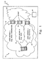
FIG. 1 illustrates a wireless communication system that includes a plurality of subnets. -
FIG. 2 illustrates a homogeneous wireless access network per the mobile agent. -
FIG. 3 illustrates a heterogeneous wireless access network per the mobile agent. -
FIG. 4 illustrates a wireless communication system that includes a subnet relation system. -
FIG. 5 illustrates user handoffs between access networks that include a mobility agent server. -
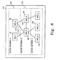
FIG. 6 illustrates an example of a subnet relation map. -
FIG. 7 is a table illustrating subnet relationships between respective mobility agent servers based on the subnet relation map illustrated inFIG. 6 . -
FIG. 8 illustrates the preferred subnet relation map application. - Referring to
FIG. 1 , a preferred embodiment of the present invention includes awireless communication network 10 that has an IP subnet 12. As set forth in greater detail below, a mobility agent server (MAS) creates the IP subnet 12. In the preferred embodiment, the IP subnet 12 includes at least onewireless communication device 14 that is capable of being connected to a plurality ofaccess networks access network server Internet connection 28. Although not illustrated, those skilled in the art would recognize that theservers wireless communication devices 14. Eachrespective server virtual operator server 30 by means of theInternet connection 28. Although not illustrated inFIG. 1 , the mobility agent server within eachaccess network servers - The present invention is capable of working on both homogeneous and heterogeneous access networks. As illustrated in
FIG. 2 as it relates to the present invention, ahomogeneous access network 40 would comprise a wireless communication system that includes a plurality of access points 42. Eachaccess point 42 of theaccess network 40 is connected to theMAS 44. Although not illustrated, eachaccess point 42 is connected to the server by way of theMAS 44. As further illustrated inFIG. 2 , eachaccess point 42 has a predefined coverage area that is represented byarea 46. - Referring to
FIG. 3 , asecond MAS 50 is connected to aheterogeneous access network 52. As clearly illustrated, aheterogeneous access network 52 is made up of a plurality ofaccess networks respective access network access point heterogeneous access network 52, thesecond MAS 50 is connected to eachaccess point different access networks FIG. 3 , theaccess networks - Referring to
FIG. 4 , which sets forth a general diagram of a preferredwireless IP network 10 used in the present invention, location information is important to manage users inwireless IP networks 10. During operation, thevirtual operator server 30 establishes a subnet relation map or database that is based on handoff experience. To complete the subnet relation map, thevirtual operator server 30 tracks IP subnet changes whenwireless communication devices 14 move from one subnet to another subnet. This movement is generally referred to as a handoff. Subnets are generally assumed to be close to each other when thewireless communication devices 14 can perform a handoff. - As illustrated in
FIG. 4 , afirst access network 70 includes a plurality ofIP subnets 72 that are connected to afirst MAS 74. Although not specifically illustrated in this figure, it should be noted that there may be more than one MAS in each access network and, as such, the use of one MAS in each access network is for illustrative purposes only and should not be construed as a limitation of the present invention. Thesecond access network 76 also includes a plurality ofIP subnets 72 that are connected to asecond MAS 78. In this preferred embodiment, eachMAS Internet connection 28 that, in turn, connects eachMAS virtual operator server 30. - Referring to
FIG. 5 , during operation, afirst user 80 has a global address assigned by thevirtual operator server 30. Thefirst user 80 also has a connection (arrow 82) to thefirst MAS 74, which is located in thefirst access network 70. Asecond user 84 also has a global address assigned by thevirtual operator server 30 and connects (arrow 86) to thesecond MAS 78, which is also located in thefirst access network 70. When thefirst user 80 performs a handoff from thefirst MAS 74 to athird MAS 88, thefirst user 80 will register its global address to the third MAS 88 (see the arrow 90). Thethird MAS 88 is located in thesecond access network 76. At the same time, thethird MAS 88 will update the MAS-global address mapping of thefirst user 80 at the virtual operator server 30 (arrow 92). - When the
second user 84 performs a handoff from thesecond MAS 78 to a fourth MAS 94 (arrow 96), thefourth MAS 94 also updates the MAS-global address mapping at the virtual operator server 30 (arrow 98). If thefirst user 80 performs another handoff from thethird MAS 88 to the second MAS 78 (arrow 100), then the MAS-global address mapping will be updated at the virtual operator server 30 (arrow 102). - In the preferred embodiment of the present invention, the
virtual operator server 30 keeps track of a pluralitywireless communication devices 14 as they handoff from MAS to MAS. Generally speaking, if one MAS is too far from another MAS, it would be impossible for the user of awireless communication device 14 to handoff to the distant MAS. Consequently, the ability to handoff usually indicates that each IP subnet is located close to each other so that there is some overlap in coverage areas. As such, thevirtual operator server 30 is capable of mapping out the respective interconnections amongst subnets within a full-scalewireless IP network 10. As such, the virtual operator server knows what subnets are located in a respective geographic location that are capable of being accessed bywireless communication devices 14. - Referring to
FIG. 6 , during operation, thevirtual operator server 30 tracks subnet relations by handoff experience and creates asubnet relation map 110. In the example set forth above, thesubnet relation map 110 shows that thefirst MAS 74 has asubnet relation 112 with thethird MAS 88, because thefirst user 80 is capable of handing off from thefirst MAS 74 to thethird MAS 88. Furthermore, thefirst user 80 is capable of handing off from thethird MAS 88 to thesecond MAS 78, thereby creating anothersubnet relation 114.Subnet relation 116 is created by the fact that thesecond user 84 is capable of handing off from thesecond MAS 78 to thefourth MAS 94. - The
subnet relation map 110 illustrated inFIG. 6 represents only a small piece of the total number of access networks that would be connected to thevirtual operator server 30. As such, thesubnet relation map 110 should be viewed in an illustrative sense and not as a limitation of the present invention. From thissubnet relation map 110, it is illustrated that thefirst MAS 74 has the ability to handoff to thethird MAS 88. In turn, thethird MAS 88 has the ability to handoff to thefirst MAS 74, thesecond MAS 78, thefourth MAS 94, afifth MAS_A 118 and asixth MAS_B 120.FIG. 7 illustrates all of the subnet relations that are possible for each MAS in the example set forth inFIG. 6 . - As it relates to the preferred embodiment of the present invention, knowing this information gives the
virtual operator server 30 the ability to assist thewireless communication device 14 in its efforts to reduce power consumption. In one preferred embodiment, thewireless communication device 14 could shut down the network interface that is associated with a particular type of subnet or set the network interface into a sleep mode. Either of these options allows thewireless communication device 14 to conserve energy by reducing or eliminating power consumption that is associated with network interfaces. -
FIG. 8 illustrates a preferredsubnet relationship application 120 that creates thesubnet relation map 110, which is located on thevirtual operator server 30. At first, a handoff is detected by ahandoff detection application 122. Thehandoff detection application 122 preferentially identifies subnet handoffs, which means that the IP address assigned by the MAS has changed because thewireless communication device 14 has moved from a current MAS territory to another MAS territory. In addition, this detection includes that this IP address change is triggered by the handoff. - If a handoff is detected, the preferred embodiment of the present invention also determines whether or not the
wireless communication device 14 initiated the handoff or some other source. Since the samewireless communication device 14 may use a different IP address at different access networks, it is necessary to know whether thewireless communication device 14 initiated the handoff in order to create a more accuratesubnet relation map 110; especially when thewireless communication device 14 has two or more access network interfaces, as each access network interface may have a different IP address. - After determining whether or not the user initiated the handoff, a subnet
relation update application 126 is used to update thesubnet relation map 110 based on the handoff. The subnet relation does not necessarily indicate a physical location, but indicates the logical relation between all of the subnets. Therefore, thevirtual operator server 30 creates and maintains thesubnet relation map 110 based only on subnet changing information (subnet handoff information). After thevirtual operator server 30 has some handoff experience, thesubnet relation map 110 becomes relatively stable. However, it is necessary to update thesubnet relation map 110 because some subnets can be instantaneously attached to an access network and also removed from the access network. - For instance, a wireless
LAN access network 18 may be attached to the wireless network 12 and removed from the wireless network 12. This movable case will happen especially in private networks. Therefore, in order to keep the accuracy of thesubnet relation map 110, atimer 128 may be used to ensure that thesubnet relation map 110 is accurate. For instance, if the handoff occurred one day ago, the subnet relation is likely still accurate even under a private network. However, if the handoff has not occurred for one year, the subnet relation may not be as clear, especially in the case of a private network. - The scope of the invention is defined by the appended independent claims.
Claims (34)
- A method for facilitating handoffs for a wireless communication device (14) having at least one network interface, comprising:providing a wireless communication system including a plurality of Internet Protocol, IP, subnets (72);attaching said wireless communication device (14) to a first IP subnet (72);said method characterized by:when said wireless communication device (14) moves from an area served by said first IP subnet (72) to an area served by a second IP subnet (72), performing a handoff from the first IP subnet to a second IP subnet and creating a subnet relation in a subnet relation database at the network operator server to indicate that the first and second IP subnets are so close to each other that there is an overlap in coverage areas and therefore handover between said IP subnets is possible; andusing said subnet relation database to determine other subnets (72) said wireless communication device can access from said area served by said second IP subnet.
- The method of claim 1, characterized in that said subnet relation database is located on a virtual operator server (30).
- The method of claim 1, characterized in that each IP subnet (72) is associated with a mobility agent server (74, 78, 88, 94, 118, 120) that monitors said wireless communication device (14).
- The method of claim 1, further characterized by notifying a mobility agent server (74, 78, 88, 94, 118, 120) associated with said second IP subnet (72) of said handoff whereupon said mobility agent server causes said IP subnet relation to be created.
- The method of claim 4, characterized in that said mobility agent notifies a virtual operator server (30) of said handoff.
- The method of claim 1, further characterized by sending a message from a virtual operator server (30) to said wireless communication device (14) that informs said wireless communication device which network interfaces may be activated.
- The method of claim 1, characterized in that said subnet relation database includes connectivity information for each IP subnet (72) among said plurality of subnets.
- The method of claim 7, characterized in that said connectivity information comprises each IP subnet to which said wireless communication device (14) can handoff from said second IP subnet (72).
- The method of claim 1, further characterized by activating a network interface if said wireless communication device (14) performs a handoff to another IP subnet (72) for which said wireless communication device could use said network interface.
- A method of monitoring subnet relations in a wireless communication system, comprising:providing a wireless communication device (14) located in an area served by a first IP subnet (72);detecting when said wireless communication device (14) executes a handoff to a second IP subnet (72);said method characterized by:creating a subnet relation between said first IP subnet and said second IP subnet to indicate that the first and second IP subnets are so close to each other that there is an overlap in coverage areas and therefore handover between said IP subnets is possible; andstoring said subnet relation.
- The method of claim 10, further characterized by notifying a mobility agent server (74, 78, 88, 94, 118, 120) when said wireless communication device (14) makes said handoff.
- The method of claim 11, further characterized by notifying a virtual operator server of said handoff to said second IP subnet (72).
- The method of claim 12, characterized in that said virtual operator server creates said subnet relation (72) .
- The method of claim 10, characterized in that said adjacency relation is stored in a subnet relation database.
- A subnet relationship monitoring system for a wireless communication system, comprising:a wireless communication device (14) with at least one network interface for connecting to a plurality of IP subnets (72);at least one mobility agent server (74, 78, 88, 94, 118, 120) associated with predetermined IP subnets within said plurality of IP subnets (72);a virtual operator server (30) connected to each mobility agent server; andsaid system is characterized by:an IP subnet relation database located on said virtual operator server, said IP subnet relations having been created upon IP subnet handoffs of users and each of said relations indicating that a first and second IP subnet corresponding to a respective relation are so close to each other that there is an overlap in coverage area of said IP subnets and that therefore handoff between said IP subnets is possible;,wherein said network operator server is operable to use said IP subnet relation database to determine which network interfaces on said wireless communication device (14) are active when said wireless communication device is served by a specific IP subnet (72).
- The wireless communication system of claim 15, characterized in that said IP subnet relation database contains connectivity information for each IP subnet (72) in said wireless communication system.
- The wireless communication system of claim 16, characterized in that said connectivity information comprises each IP subnet (72) to which said wireless communication device can handoff to from within the area served by said specific IP subnet.
- The wireless communication system of claim 15, characterized in that non-active network interfaces are placed in a power-saving mode by said wireless communication device (14).
- A method for managing subnet relations in a wireless communication device (14) including at least one network interface, comprising:providing a plurality of access networks that each include at least one Internet Protocol, IP, subnet (72);connecting said wireless communication device to an IP subnet;said method characterized by:creating an IP subnet relation database, said IP subnet relations having been created upon IP subnet handoffs of users and each of said relations indicating that a first and second IP subnet corresponding to a respective relation are so close to each other that there is an overlap in coverage area of said IP subnets and that therefore handoff between said IP subnets is possible;determining which surrounding IP subnets that said wireless communication device is capable of performing a handoff to from an area served by said subnet (by using said IP subnet relation database).
- The method of claim 19, characterized in that each IP subnet (72) within said access networks is associated with a mobility agent server (74, 78, 88, 94, 118, 120).
- The method of claim 20, characterized in that each mobility agent server is connected to a virtual operator server (30).
- The method of claim 21, characterized in that each said virtual operator server (30) is responsible for generating a signal that is transmitted to said wireless communication device (14) to place each network interface in a power-saving mode.
- The method of claim 4, characterized in that said wireless communication device (14) is assigned a global address, and wherein, during said handoff, said wireless communication device registers said global address with said mobility agent server (74, 78, 88, 94, 118, 120).
- The method of claim 23, characterized in that said IP subnet relation database resides in a virtual operator server (30), and wherein, upon registration, said mobility agent server provides said global address to said virtual operator server (30).
- The method of claim 23, characterized in that said handoff occurs between IP subnets (72) of different access networks.
- The method of claim 11, characterized in that said wireless communication device (14) is assigned a global address, and wherein, during said handoff, said wireless communication device registers said global address with said mobility agent server (74, 78, 88, 94, 118, 120).
- The method of claim 26, characterized in that said subnet relation is stored in a subnet relation database residing in a virtual operator server (30), and wherein, upon registration, said mobility agent server provides said global address to said virtual operator server (30).
- The method of claim 27, characterized in that said handoff occurs between IP subnets of different access networks.
- The subnet relationship monitoring system as in claim 15, characterized in that said wireless communication device (14) is assigned a global address and wherein, during a handoff from a first IP subnet to a second IP subnet, said wireless communication device (14) deregisters said global address from a mobility agent server associated with said first IP subnet and registers said global address with a mobility agent of said second IP subnet.
- The subnet relationship monitoring system as in claim 29, characterized in that , upon registration, said mobility agent server (74, 78, 88, 94, 118, 120) of said second IP subnet provides said global address to said virtual operator server (30).
- The subnet relationship monitoring system of claim 30, characterized in that said first and second IP subnets (72) are associated with different access networks.
- The method of claim 19, characterized in that said wireless communication device (14) is assigned a global address and wherein, during said handoff, said wireless communication device (14) deregisters said global address from one IP subnet and registers said global address with another subject.
- The method of claim 32, characterized in that each IP subnet is associated with a mobility agent server (74, 78, 88, 94, 118, 120), and wherein, upon registration, said mobility agent associated with said another IP subnet causes a subnet relation to be created and stored in an a subnet relation database residing in a virtual operator server (30), and provides said global address to said virtual operator server.
- The method of claim 33, characterized in that said handoff occurs between IP subnets (72) of different access networks.
Applications Claiming Priority (4)
| Application Number | Priority Date | Filing Date | Title |
|---|---|---|---|
| US35456802P | 2002-02-06 | 2002-02-06 | |
| US354568P | 2002-02-06 | ||
| US120164 | 2002-04-10 | ||
| US10/120,164 US7236475B2 (en) | 2002-02-06 | 2002-04-10 | Using subnet relations to conserve power in a wireless communication device |
Publications (3)
| Publication Number | Publication Date |
|---|---|
| EP1335528A2 EP1335528A2 (en) | 2003-08-13 |
| EP1335528A3 EP1335528A3 (en) | 2004-01-14 |
| EP1335528B1 true EP1335528B1 (en) | 2011-11-16 |
Family
ID=27616129
Family Applications (1)
| Application Number | Title | Priority Date | Filing Date |
|---|---|---|---|
| EP02014837A Expired - Lifetime EP1335528B1 (en) | 2002-02-06 | 2002-07-03 | Using subnet relations to perform handover in a wireless communication device |
Country Status (4)
| Country | Link |
|---|---|
| US (1) | US7236475B2 (en) |
| EP (1) | EP1335528B1 (en) |
| JP (2) | JP4515711B2 (en) |
| AT (1) | ATE534214T1 (en) |
Cited By (1)
| Publication number | Priority date | Publication date | Assignee | Title |
|---|---|---|---|---|
| US11057309B2 (en) * | 2017-02-27 | 2021-07-06 | Huawei Technologies Co., Ltd. | Management method, management unit, and system |
Families Citing this family (22)
| Publication number | Priority date | Publication date | Assignee | Title |
|---|---|---|---|---|
| EP1526752B1 (en) * | 2002-02-06 | 2011-11-09 | Ntt Docomo, Inc. | Using subnet relations for authentication, association and to activate network interfaces in heterogeneous access networks |
| US7366524B2 (en) | 2002-02-06 | 2008-04-29 | Ntt Docomo Inc. | Using subnet relations for paging, authentication, association and to activate network interfaces in heterogeneous access networks |
| US7236475B2 (en) * | 2002-02-06 | 2007-06-26 | Ntt Docomo, Inc. | Using subnet relations to conserve power in a wireless communication device |
| US7047036B2 (en) | 2002-07-02 | 2006-05-16 | Interdigital Technology Corporation | Method and apparatus for handoff between a wireless local area network (WLAN) and a universal mobile telecommunication system (UMTS) |
| US8224699B2 (en) * | 2002-09-18 | 2012-07-17 | Nds Limited | System for multimedia viewing based on entitlements |
| KR100448318B1 (en) * | 2002-11-08 | 2004-09-16 | 삼성전자주식회사 | Method for hand-off in a wileless network |
| US8037188B2 (en) * | 2003-02-12 | 2011-10-11 | Qualcomm Incorporated | Soft handoff across different networks assisted by an end-to-end application protocol |
| US7421591B2 (en) * | 2003-08-29 | 2008-09-02 | Dell Products L.P. | Data flow control system and method for conserving power in a power managed system |
| CN1879335A (en) * | 2003-11-12 | 2006-12-13 | 美商内数位科技公司 | System for application server autonomous access across different types of access technology networks |
| TWI366385B (en) | 2003-11-13 | 2012-06-11 | Interdigital Tech Corp | Method and system for facilitating inter-system handover |
| WO2005089249A2 (en) | 2004-03-12 | 2005-09-29 | Interdigital Technology Corporation | Method and system for switching a radio access technology between wireless communicaiton systems with a multi-mode wireless transmit/receive unit |
| FR2871980B1 (en) * | 2004-06-22 | 2006-08-04 | Radiotelephone Sfr | METHOD AND SYSTEM FOR CALCULATING 2G-3G NEIGHBORHOOD FOR AUTOMATIC CONNECTION TRANSFER BETWEEN 2G AND 3G SYSTEMS |
| KR100891110B1 (en) * | 2004-06-28 | 2009-03-30 | 삼성전자주식회사 | Method and apparatus for performing handover |
| KR100739183B1 (en) * | 2005-12-30 | 2007-07-13 | 엘지전자 주식회사 | Mobile communications terminal and method for reducing power consumption of a first communications module according to the activation of a second communications module |
| EP1933576A1 (en) * | 2006-12-14 | 2008-06-18 | France Télécom | Method and system to enhance network neighboring map with hierarchical structure and pre-decision metrics |
| TW200826554A (en) * | 2006-12-15 | 2008-06-16 | Inst Information Industry | Measuring system and method of heterogeneous network mobile communication apparatus and recording medium thereof |
| MX2010002218A (en) | 2007-10-02 | 2010-03-17 | Ericsson Telefon Ab L M | Including in the uplink grant an indication of specific amount of cqi to be reported. |
| TWI360309B (en) * | 2008-06-25 | 2012-03-11 | Ind Tech Res Inst | Transmission method and transmission system |
| CN101873679B (en) * | 2009-04-23 | 2016-07-06 | 瑞昱半导体股份有限公司 | There is device and the correlation technique of the network system of electricity-saving function |
| US9762748B2 (en) | 2009-06-08 | 2017-09-12 | Mitel Networks Corporation | Power management in an internet protocol (IP) telephone |
| US8515340B2 (en) * | 2009-06-08 | 2013-08-20 | Mitel Networks Corporation | Power management in an internet protocol (IP) telephone |
| JP5422738B2 (en) * | 2009-06-12 | 2014-02-19 | ブラックベリー リミテッド | Method and apparatus for managing mobile handover |
Family Cites Families (23)
| Publication number | Priority date | Publication date | Assignee | Title |
|---|---|---|---|---|
| JPH05268138A (en) | 1992-03-19 | 1993-10-15 | Nec Corp | Portable telephone |
| US5640676A (en) | 1995-05-11 | 1997-06-17 | Motorola, Inc. | Method for generating a handoff candidate list |
| JP3483997B2 (en) * | 1995-05-31 | 2004-01-06 | 株式会社東芝 | Wireless communication system, wireless terminal device, and power control method |
| US5854981A (en) * | 1995-08-08 | 1998-12-29 | Telefonaktiebolaget L M Ericsson | Adaptive neighbor cell list |
| JP3397573B2 (en) * | 1996-04-10 | 2003-04-14 | 株式会社エヌ・ティ・ティ・ドコモ | Mobile communication method |
| JP3581251B2 (en) * | 1998-06-16 | 2004-10-27 | 株式会社東芝 | Communication system, data packet transfer method, router device, and packet relay device |
| US6295450B1 (en) | 1998-06-23 | 2001-09-25 | Motorola, Inc. | Method and apparatus for transferring communication within a communication system |
| JP4057715B2 (en) * | 1998-09-16 | 2008-03-05 | 株式会社東芝 | Router device, wireless terminal device, wireless base station, and message transmission control method |
| US6480476B1 (en) * | 1998-10-15 | 2002-11-12 | Telefonaktiebolaget Lm Ericsson (Publ) | Variable sleep mode for mobile stations in a mobile communications |
| US6160804A (en) * | 1998-11-13 | 2000-12-12 | Lucent Technologies Inc. | Mobility management for a multimedia mobile network |
| JP2000333248A (en) * | 1999-05-14 | 2000-11-30 | Mitsubishi Materials Corp | Radio server, base radio and mobile radio unit |
| JP3406867B2 (en) | 1999-09-29 | 2003-05-19 | 株式会社東芝 | Mobile communication terminal |
| US6438117B1 (en) | 2000-01-07 | 2002-08-20 | Qualcomm Incorporated | Base station synchronization for handover in a hybrid GSM/CDMA network |
| CA2330709C (en) * | 2000-02-09 | 2005-08-30 | Lucent Technologies Inc. | Handoff system for wireless communications |
| JP4060021B2 (en) * | 2000-02-21 | 2008-03-12 | 富士通株式会社 | Mobile communication service providing system and mobile communication service providing method |
| CA2813744C (en) * | 2000-03-03 | 2017-05-09 | Qualcomm Incorporated | Method and apparatus for participating in group communication services in an existing communication system |
| FI20000662A (en) | 2000-03-21 | 2001-09-22 | Nokia Oyj | Cell exchange in a network that supports multiple mediation techniques |
| FI20000700A (en) * | 2000-03-24 | 2001-09-25 | Nokia Mobile Phones Ltd | Mobile phone with improved power saving feature |
| JP3580250B2 (en) * | 2000-12-22 | 2004-10-20 | 株式会社デンソー | Wireless communication system, network and mobile terminal used in wireless communication system |
| US7184710B2 (en) * | 2001-02-13 | 2007-02-27 | Telefonaktiebolaget Lm Ericsson (Publ) | Transmission of filtering/filtered information over the lur interface |
| US6744753B2 (en) * | 2001-11-01 | 2004-06-01 | Nokia Corporation | Local service handover |
| US7236475B2 (en) * | 2002-02-06 | 2007-06-26 | Ntt Docomo, Inc. | Using subnet relations to conserve power in a wireless communication device |
| US7366524B2 (en) | 2002-02-06 | 2008-04-29 | Ntt Docomo Inc. | Using subnet relations for paging, authentication, association and to activate network interfaces in heterogeneous access networks |
-
2002
- 2002-04-10 US US10/120,164 patent/US7236475B2/en not_active Expired - Fee Related
- 2002-07-03 EP EP02014837A patent/EP1335528B1/en not_active Expired - Lifetime
- 2002-07-03 AT AT02014837T patent/ATE534214T1/en active
-
2003
- 2003-02-05 JP JP2003028859A patent/JP4515711B2/en not_active Expired - Fee Related
-
2010
- 2010-02-17 JP JP2010032393A patent/JP5009386B2/en not_active Expired - Fee Related
Cited By (1)
| Publication number | Priority date | Publication date | Assignee | Title |
|---|---|---|---|---|
| US11057309B2 (en) * | 2017-02-27 | 2021-07-06 | Huawei Technologies Co., Ltd. | Management method, management unit, and system |
Also Published As
| Publication number | Publication date |
|---|---|
| EP1335528A2 (en) | 2003-08-13 |
| US20030147364A1 (en) | 2003-08-07 |
| JP5009386B2 (en) | 2012-08-22 |
| US7236475B2 (en) | 2007-06-26 |
| JP2003258720A (en) | 2003-09-12 |
| EP1335528A3 (en) | 2004-01-14 |
| ATE534214T1 (en) | 2011-12-15 |
| JP2010154552A (en) | 2010-07-08 |
| JP4515711B2 (en) | 2010-08-04 |
Similar Documents
| Publication | Publication Date | Title |
|---|---|---|
| EP1335528B1 (en) | Using subnet relations to perform handover in a wireless communication device | |
| EP1339250B1 (en) | Using subnet relations for paging in heterogeneous access networks | |
| AU2009210419B2 (en) | System and method for implementing a media independent handover | |
| JP3356707B2 (en) | Mobile communication terminal | |
| EP2628337B1 (en) | Method in a network node for selecting a gateway in a wireless communications network | |
| US7251489B2 (en) | Wireless base station neighbor discovery in a communication system, such as a system employing a short-range frequency hopping scheme | |
| US7680081B2 (en) | Mobile node | |
| JP4726178B2 (en) | How to transfer a mobile communication session | |
| EP1959621A1 (en) | A method and device for managing the power in the isomery network handover | |
| US8331275B2 (en) | Apparatus and method for proxying powered off interfaces using the active interface | |
| US8467348B2 (en) | Power optimized station connection manager in IEEE 802.11 type stations | |
| JP2007104496A (en) | System switching control station device and system switching method | |
| EP1526752B1 (en) | Using subnet relations for authentication, association and to activate network interfaces in heterogeneous access networks | |
| CN101263685A (en) | Radio communication terminal and network side communication apparatus | |
| An et al. | Enhanced fast handover mechanism using MIH services in MIPv6 | |
| KR100612650B1 (en) | Method for transfering downlink traffic in wireless portable internet system and protocol configuration method thereof | |
| EP1962532B1 (en) | System and method for enabling wireless data transfer | |
| Lim et al. | A Framework for Implementing IEEE 802.21 Media-Independent Handover Services | |
| EP1962533B1 (en) | System and method for enabling wireless data transfer | |
| CN117835346A (en) | Method, device, terminal equipment and storage medium for processing measurement report |
Legal Events
| Date | Code | Title | Description |
|---|---|---|---|
| PUAI | Public reference made under article 153(3) epc to a published international application that has entered the european phase |
Free format text: ORIGINAL CODE: 0009012 |
|
| AK | Designated contracting states |
Designated state(s): AT BE BG CH CY CZ DE DK EE ES FI FR GB GR IE IT LI LU MC NL PT SE SK TR |
|
| AX | Request for extension of the european patent |
Extension state: AL LT LV MK RO SI |
|
| RIN1 | Information on inventor provided before grant (corrected) |
Inventor name: KURAKAKE, SHOJI Inventor name: WATANABE, FUJIO Inventor name: CAO, JINGJUN |
|
| PUAL | Search report despatched |
Free format text: ORIGINAL CODE: 0009013 |
|
| AK | Designated contracting states |
Kind code of ref document: A3 Designated state(s): AT BE BG CH CY CZ DE DK EE ES FI FR GB GR IE IT LI LU MC NL PT SE SK TR |
|
| AX | Request for extension of the european patent |
Extension state: AL LT LV MK RO SI |
|
| RIC1 | Information provided on ipc code assigned before grant |
Ipc: 7H 04L 29/06 B Ipc: 7H 04L 12/28 A Ipc: 7H 04L 12/56 B |
|
| 17P | Request for examination filed |
Effective date: 20040319 |
|
| 17Q | First examination report despatched |
Effective date: 20040512 |
|
| AKX | Designation fees paid |
Designated state(s): AT BE BG CH CY CZ DE DK EE ES FI FR GB GR IE IT LI LU MC NL PT SE SK TR |
|
| RAP1 | Party data changed (applicant data changed or rights of an application transferred) |
Owner name: NTT DOCOMO INC. |
|
| RTI1 | Title (correction) |
Free format text: USING SUBNET RELATIONS TO PERFORM HANDOVER IN A WIRELESS COMMUNICATION DEVICE |
|
| GRAP | Despatch of communication of intention to grant a patent |
Free format text: ORIGINAL CODE: EPIDOSNIGR1 |
|
| RIC1 | Information provided on ipc code assigned before grant |
Ipc: H04W 8/16 20090101ALI20110518BHEP Ipc: H04L 12/56 20060101ALI20110518BHEP Ipc: H04L 29/06 20060101ALI20110518BHEP Ipc: H04L 12/28 20060101AFI20110518BHEP |
|
| GRAS | Grant fee paid |
Free format text: ORIGINAL CODE: EPIDOSNIGR3 |
|
| GRAA | (expected) grant |
Free format text: ORIGINAL CODE: 0009210 |
|
| RAP1 | Party data changed (applicant data changed or rights of an application transferred) |
Owner name: NTT DOCOMO, INC. |
|
| RIN1 | Information on inventor provided before grant (corrected) |
Inventor name: CAO, JINGJUN Inventor name: WATANABE, FUJIO Inventor name: KURAKAKE, SHOJI |
|
| AK | Designated contracting states |
Kind code of ref document: B1 Designated state(s): AT BE BG CH CY CZ DE DK EE ES FI FR GB GR IE IT LI LU MC NL PT SE SK TR |
|
| REG | Reference to a national code |
Ref country code: GB Ref legal event code: FG4D |
|
| REG | Reference to a national code |
Ref country code: CH Ref legal event code: EP |
|
| REG | Reference to a national code |
Ref country code: IE Ref legal event code: FG4D |
|
| REG | Reference to a national code |
Ref country code: DE Ref legal event code: R096 Ref document number: 60241547 Country of ref document: DE Effective date: 20120119 |
|
| REG | Reference to a national code |
Ref country code: NL Ref legal event code: VDEP Effective date: 20111116 |
|
| PG25 | Lapsed in a contracting state [announced via postgrant information from national office to epo] |
Ref country code: BE Free format text: LAPSE BECAUSE OF FAILURE TO SUBMIT A TRANSLATION OF THE DESCRIPTION OR TO PAY THE FEE WITHIN THE PRESCRIBED TIME-LIMIT Effective date: 20111116 Ref country code: NL Free format text: LAPSE BECAUSE OF FAILURE TO SUBMIT A TRANSLATION OF THE DESCRIPTION OR TO PAY THE FEE WITHIN THE PRESCRIBED TIME-LIMIT Effective date: 20111116 Ref country code: GR Free format text: LAPSE BECAUSE OF FAILURE TO SUBMIT A TRANSLATION OF THE DESCRIPTION OR TO PAY THE FEE WITHIN THE PRESCRIBED TIME-LIMIT Effective date: 20120217 Ref country code: SE Free format text: LAPSE BECAUSE OF FAILURE TO SUBMIT A TRANSLATION OF THE DESCRIPTION OR TO PAY THE FEE WITHIN THE PRESCRIBED TIME-LIMIT Effective date: 20111116 Ref country code: PT Free format text: LAPSE BECAUSE OF FAILURE TO SUBMIT A TRANSLATION OF THE DESCRIPTION OR TO PAY THE FEE WITHIN THE PRESCRIBED TIME-LIMIT Effective date: 20120316 |
|
| PG25 | Lapsed in a contracting state [announced via postgrant information from national office to epo] |
Ref country code: CY Free format text: LAPSE BECAUSE OF FAILURE TO SUBMIT A TRANSLATION OF THE DESCRIPTION OR TO PAY THE FEE WITHIN THE PRESCRIBED TIME-LIMIT Effective date: 20111116 |
|
| PG25 | Lapsed in a contracting state [announced via postgrant information from national office to epo] |
Ref country code: CZ Free format text: LAPSE BECAUSE OF FAILURE TO SUBMIT A TRANSLATION OF THE DESCRIPTION OR TO PAY THE FEE WITHIN THE PRESCRIBED TIME-LIMIT Effective date: 20111116 Ref country code: DK Free format text: LAPSE BECAUSE OF FAILURE TO SUBMIT A TRANSLATION OF THE DESCRIPTION OR TO PAY THE FEE WITHIN THE PRESCRIBED TIME-LIMIT Effective date: 20111116 Ref country code: EE Free format text: LAPSE BECAUSE OF FAILURE TO SUBMIT A TRANSLATION OF THE DESCRIPTION OR TO PAY THE FEE WITHIN THE PRESCRIBED TIME-LIMIT Effective date: 20111116 Ref country code: BG Free format text: LAPSE BECAUSE OF FAILURE TO SUBMIT A TRANSLATION OF THE DESCRIPTION OR TO PAY THE FEE WITHIN THE PRESCRIBED TIME-LIMIT Effective date: 20120216 Ref country code: SK Free format text: LAPSE BECAUSE OF FAILURE TO SUBMIT A TRANSLATION OF THE DESCRIPTION OR TO PAY THE FEE WITHIN THE PRESCRIBED TIME-LIMIT Effective date: 20111116 |
|
| PG25 | Lapsed in a contracting state [announced via postgrant information from national office to epo] |
Ref country code: IT Free format text: LAPSE BECAUSE OF FAILURE TO SUBMIT A TRANSLATION OF THE DESCRIPTION OR TO PAY THE FEE WITHIN THE PRESCRIBED TIME-LIMIT Effective date: 20111116 |
|
| REG | Reference to a national code |
Ref country code: AT Ref legal event code: MK05 Ref document number: 534214 Country of ref document: AT Kind code of ref document: T Effective date: 20111116 |
|
| PLBE | No opposition filed within time limit |
Free format text: ORIGINAL CODE: 0009261 |
|
| STAA | Information on the status of an ep patent application or granted ep patent |
Free format text: STATUS: NO OPPOSITION FILED WITHIN TIME LIMIT |
|
| 26N | No opposition filed |
Effective date: 20120817 |
|
| PGFP | Annual fee paid to national office [announced via postgrant information from national office to epo] |
Ref country code: GB Payment date: 20120725 Year of fee payment: 11 |
|
| REG | Reference to a national code |
Ref country code: DE Ref legal event code: R097 Ref document number: 60241547 Country of ref document: DE Effective date: 20120817 |
|
| PGFP | Annual fee paid to national office [announced via postgrant information from national office to epo] |
Ref country code: FR Payment date: 20120810 Year of fee payment: 11 Ref country code: DE Payment date: 20120726 Year of fee payment: 11 |
|
| PG25 | Lapsed in a contracting state [announced via postgrant information from national office to epo] |
Ref country code: AT Free format text: LAPSE BECAUSE OF FAILURE TO SUBMIT A TRANSLATION OF THE DESCRIPTION OR TO PAY THE FEE WITHIN THE PRESCRIBED TIME-LIMIT Effective date: 20111116 |
|
| PG25 | Lapsed in a contracting state [announced via postgrant information from national office to epo] |
Ref country code: MC Free format text: LAPSE BECAUSE OF NON-PAYMENT OF DUE FEES Effective date: 20120731 |
|
| REG | Reference to a national code |
Ref country code: CH Ref legal event code: PL |
|
| PG25 | Lapsed in a contracting state [announced via postgrant information from national office to epo] |
Ref country code: LI Free format text: LAPSE BECAUSE OF NON-PAYMENT OF DUE FEES Effective date: 20120731 Ref country code: ES Free format text: LAPSE BECAUSE OF FAILURE TO SUBMIT A TRANSLATION OF THE DESCRIPTION OR TO PAY THE FEE WITHIN THE PRESCRIBED TIME-LIMIT Effective date: 20120227 Ref country code: CH Free format text: LAPSE BECAUSE OF NON-PAYMENT OF DUE FEES Effective date: 20120731 |
|
| REG | Reference to a national code |
Ref country code: IE Ref legal event code: MM4A |
|
| PG25 | Lapsed in a contracting state [announced via postgrant information from national office to epo] |
Ref country code: FI Free format text: LAPSE BECAUSE OF FAILURE TO SUBMIT A TRANSLATION OF THE DESCRIPTION OR TO PAY THE FEE WITHIN THE PRESCRIBED TIME-LIMIT Effective date: 20111116 |
|
| PG25 | Lapsed in a contracting state [announced via postgrant information from national office to epo] |
Ref country code: IE Free format text: LAPSE BECAUSE OF NON-PAYMENT OF DUE FEES Effective date: 20120703 |
|
| GBPC | Gb: european patent ceased through non-payment of renewal fee |
Effective date: 20130703 |
|
| REG | Reference to a national code |
Ref country code: FR Ref legal event code: ST Effective date: 20140331 |
|
| PG25 | Lapsed in a contracting state [announced via postgrant information from national office to epo] |
Ref country code: TR Free format text: LAPSE BECAUSE OF FAILURE TO SUBMIT A TRANSLATION OF THE DESCRIPTION OR TO PAY THE FEE WITHIN THE PRESCRIBED TIME-LIMIT Effective date: 20111116 Ref country code: DE Free format text: LAPSE BECAUSE OF NON-PAYMENT OF DUE FEES Effective date: 20140201 Ref country code: GB Free format text: LAPSE BECAUSE OF NON-PAYMENT OF DUE FEES Effective date: 20130703 |
|
| REG | Reference to a national code |
Ref country code: DE Ref legal event code: R119 Ref document number: 60241547 Country of ref document: DE Effective date: 20140201 |
|
| PG25 | Lapsed in a contracting state [announced via postgrant information from national office to epo] |
Ref country code: FR Free format text: LAPSE BECAUSE OF NON-PAYMENT OF DUE FEES Effective date: 20130731 Ref country code: LU Free format text: LAPSE BECAUSE OF NON-PAYMENT OF DUE FEES Effective date: 20120703 |