EP1335408A2 - Electrodeless lighting system - Google Patents
Electrodeless lighting system Download PDFInfo
- Publication number
- EP1335408A2 EP1335408A2 EP02016899A EP02016899A EP1335408A2 EP 1335408 A2 EP1335408 A2 EP 1335408A2 EP 02016899 A EP02016899 A EP 02016899A EP 02016899 A EP02016899 A EP 02016899A EP 1335408 A2 EP1335408 A2 EP 1335408A2
- Authority
- EP
- European Patent Office
- Prior art keywords
- housing
- heat
- radiator
- generating unit
- microwave generating
- Prior art date
- Legal status (The legal status is an assumption and is not a legal conclusion. Google has not performed a legal analysis and makes no representation as to the accuracy of the status listed.)
- Granted
Links
Images


Classifications
-
- H—ELECTRICITY
- H01—ELECTRIC ELEMENTS
- H01J—ELECTRIC DISCHARGE TUBES OR DISCHARGE LAMPS
- H01J61/00—Gas-discharge or vapour-discharge lamps
- H01J61/02—Details
- H01J61/52—Cooling arrangements; Heating arrangements; Means for circulating gas or vapour within the discharge space
-
- H—ELECTRICITY
- H01—ELECTRIC ELEMENTS
- H01J—ELECTRIC DISCHARGE TUBES OR DISCHARGE LAMPS
- H01J65/00—Lamps without any electrode inside the vessel; Lamps with at least one main electrode outside the vessel
- H01J65/04—Lamps in which a gas filling is excited to luminesce by an external electromagnetic field or by external corpuscular radiation, e.g. for indicating plasma display panels
- H01J65/042—Lamps in which a gas filling is excited to luminesce by an external electromagnetic field or by external corpuscular radiation, e.g. for indicating plasma display panels by an external electromagnetic field
- H01J65/044—Lamps in which a gas filling is excited to luminesce by an external electromagnetic field or by external corpuscular radiation, e.g. for indicating plasma display panels by an external electromagnetic field the field being produced by a separate microwave unit
Definitions
- the conventional electrodeless lighting system includes a microwave generating unit 10 installed inside a housing 50 and generating microwave energy; a power supply unit 40 applying power to the microwave generating unit 10; a waveguide 20 connected to the microwave generating unit 10 and transmitting the microwave energy generated in the microwave generating unit 10; a light emitting unit 30 forming plasma 20 and generating light by being excited by the microwave energy transmitted through the waveguide 20; and a cooling fan 60 installed at a certain side of the housing 50 and cooling the microwave generating unit 10 and the power supply unit 40.
- the heat insulating wall 510 can be placed between the waveguide 200 and the magnetron 200, in that case, assembly can be performed after fabricating the heat insulating wall 510 separately, or the heat insulating wall 510 can be fabricated at a certain side surface of the waveguide 200 as one body.
- the fan housing 820 is fixedly combined with the housing 500 by a connecting member 825, etc.
- the radiator 720 is placed in the air path.
- the radiator 720 can be fabricated as Figure 2 or 5. In Figure 8, the radiator 720 in Figure 5 is used.
Abstract
Description
- The present invention relates to an electrodeless lighting system, and in particular to an electrodeless lighting system having a cooling unit capable of cooling a radiating unit therein.
- An electrodeless lighting system generates light by forming plasma by exciting light emitting materials charged inside a bulb as a vacuum state with microwave energy.
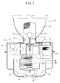
- Figure 1 is a schematic longitudinal sectional view illustrating a construction of the conventional electrodeless lighting system.
- As depicted in Figure 1, the conventional electrodeless lighting system includes a
microwave generating unit 10 installed inside ahousing 50 and generating microwave energy; apower supply unit 40 applying power to themicrowave generating unit 10; awaveguide 20 connected to themicrowave generating unit 10 and transmitting the microwave energy generated in themicrowave generating unit 10; alight emitting unit 30 formingplasma 20 and generating light by being excited by the microwave energy transmitted through thewaveguide 20; and acooling fan 60 installed at a certain side of thehousing 50 and cooling themicrowave generating unit 10 and thepower supply unit 40. - The
light emitting unit 30 includes abulb 31 in which light emitting materials are charged, awaveguide 20, aresonator 32 covering the front of thebulb 31 to cut off microwave energy and pass light generated in thebulb 31, a reflectingmirror 33 receiving theresonator 32 and intensely reflecting light generated in thebulb 31 straight and adielectric mirror 34 passing microwave energy and reflecting light. - In the
housing 50, acooling fan 60 is received, anair suction hole 61 is formed at the lower portion corresponding to thecooling fan 60, anair path 62 is formed at the right and left portions of theair suction hole 61, and anair outlet 63 is formed at the upper portion of thehousing 50 so as to correspond to the both ends of theair path 62. - The
microwave generating unit 10 and thepower supply unit 40 are placed between theair path 62 and theair outlet 63 and are respectively combined to the both sides of thewaveguide 20. - A non-explained
reference numeral 35 is an axial portion, M1 is a bulb motor rotating thebulb 31, and M2 is a fan motor rotating thecooling fan 60. - The operation of the conventional electrodeless lighting system will be described in more detail.
- According to an operation signal from a control unit (not shown), the
power supply unit 40 supplies power to themicrowave generating unit 10, and themicrowave generating unit 10 generates microwave energy having a high frequency. - While the microwave energy generated in the
microwave generating unit 10 is transmitted into theresonator 32 through thewaveguide 20, the light emitting materials charged inside thebulb 31 are excited and form plasma, and accordingly light is generated. The generated light lights the surroundings by being reflected by thereflecting mirror 33 and thedielectric mirror 34 toward the front. - In the meantime, while the electrodeless lighting system operates, lots of heat occurs in the
microwave generating unit 10 and thepower supply unit 40, etc., in particular, in themicrowave generating unit 10 such as a magnetron, part of high frequency energy generated by thermal electron is not discharged but converted into heat, and accordingly an internal temperature of thehousing 50 rises. - And, heat generated in the
microwave generating unit 10 and thepower supply unit 40, etc. may damage the internal units of the electrodeless lighting system such as the magnetron and thepower supply unit 40 or cause unstableness of the system. - Accordingly, there is a need to cool the heat generated in the
microwave generating unit 10 and thepower supply unit 40, etc., as depicted in Figure 1, in the conventional electrodeless lighting system, to cool heat generated in themicrowave generating unit 10, etc. outer air flows into thehousing 50 by operating thecooling fan 60. - However, in the conventional electrodeless lighting system, because outer air flows into the
housing 50 by operating thecooling fan 60, impurities may penetrate into thehousing 50, and accordingly the internal units may be damaged. Particularly, when the electrodeless lighting system is installed at the exterior, rain drops or other impurities may penetrate into thehousing 50, and accordingly various parts may be damaged. - In order to solve the above-mentioned problems, it is an object of the present invention to provide an electrodeless lighting system having a cooling unit capable of being installed in a housing and efficiently cooling a microwave generating unit sealed in the housing.
- In order to achieve the above-mentioned object, an electrodeless lighting system in accordance with the present invention includes a microwave generating unit for generating microwave energy; a light emitting unit connected to the microwave generating unit and emitting light by forming plasma by the microwave energy generated in the microwave generating unit; a housing having a first receiving space for receiving the microwave generating unit and sealed-combined with the light emitting unit; a heat exchanger installed at the outer surface of the microwave generating unit to absorb heat generated in the microwave generating unit; a radiator installed at the outer surface of the housing; and a heat transfer member at which one end is connected to the heat exchanger and the other end is connected to the radiator by penetrating the housing to transmit heat from the heat exchanger to the radiator.
- The system further includes a fan housing having an air inlet hole for air inflow, an air discharge hole for discharging air and an air path connected to the air inlet hole and the air discharge hole and fixedly installed at the outer surface of the housing; and a fan installed in the air path to generate air flow in the air path; wherein the radiator is installed in the air path.
- The accompanying drawings, which are included to provide a further understanding of the invention and are incorporated in and constitute a part of this specification, illustrate embodiments of the invention and together with the description serve to explain the principles of the invention.
- In the drawings:
- Figure 1 is a longitudinal sectional view illustrating a construction of the conventional electrodeless lighting system;
- Figure 2 is a longitudinal sectional view illustrating an electrodeless lighting system in accordance with an embodiment of the present invention;
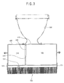
- Figure 3 is a longitudinal sectional view illustrating a housing of the electrodeless lighting system in Figure 2;
- Figure 4 is a partial longitudinal-sectional view illustrating a magnetron, which is connected to a waveguide by a coaxial cable, of the electrodeless lighting system in Figure 3;
- Figure 5 is a partial transverse-sectional view illustrating a radiator, which is installed to a housing after interposing a heat insulating member between them, of the electrodeless lighting system in Figure 3;
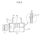
- Figure 6 is a partial longitudinal-sectional view illustrating a construction of a waveguide of the electrodeless lighting system in Figure 3;
- Figure 7 is a partial longitudinal-sectional view illustrating a power supply unit, at which a heat transfer member is connected, of the electrodeless lighting system in Figure 3;
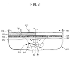
- Figure 8 is a partial expanded view illustrating a fan assembly additionally installed at the electrodeless lighting system in Figure 2; and
- Figure 9 is a partial expanded view illustrating another fan assembly additionally installed at the electrodeless lighting system in Figure 2.
-
- Hereinafter, an electrodeless lighting system in accordance with the present invention will be described in detail with reference to accompanying Figures 2 ∼ 7.
- As depicted in Figure 2, the electrodeless lighting system in accordance with the present invention includes a
magnetron 100 as a microwave generating unit for generating microwave energy; alight emitting unit 300 connected to themagnetron 100 and emitting light by forming plasma according to the microwave energy generated in themagnetron 100; ahousing 500 having amagnetron receiving space 110 for receiving themagnetron 100 and sealed-combined with thelight emitting unit 300; aheat exchanger 710 installed at the outer surface of themagnetron 100 to absorb heat generated in themagnetron 100; aradiator 720 installed at the outer surface of thehousing 500; and aheat transfer member 730 at which one end is connected to theheat exchanger 710 and the other end is connected to theradiator 720 by penetrating thehousing 500 to transmit heat from theheat exchanger 710 to theradiator 720. - The
light emitting unit 300 includes abulb 310 in which light emitting materials are charged, awaveguide 200, aresonator 320 covering the front of thebulb 310 to cut off microwave energy and pass light generated in thebulb 310, a reflectingmirror 330 receiving theresonator 320 and intensely reflecting light generated in thebulb 310 straight and adielectric mirror 340 passing microwave and reflecting light. - The
light emitting unit 300 is connected to themagnetron 100 by thewaveguide 200 transmitting microwave energy generated in themagnetron 100 to thelight emitting unit 300. - As depicted in Figures 2 and 3, the
housing 500 is made of a material having a high heat conductivity, anopening 210 of thewaveguide 200 assembled with thelight emitting unit 300 is formed at the front surface, and ahole 731 is formed at the rear surface to pass and connect theheat transfer member 730 with theradiator 720. - In the
housing 500, a receiving space is formed to receive internal units such as the magnetron, etc., it is sealed by combining with thelight emitting unit 300. In addition, to separately receive themagnetron 100 from other internal units, aheat insulating wall 510 is formed to divide the receiving space into amagnetron receiving space 110 and an otherunits receiving space 120. - In order to receive a part of the
waveguide 200 with themagnetron 100 inside themagnetron receiving space 110, theheat insulating wall 510 can be fabricated as a plate member (not shown) covering the middle portion of thewaveguide 200, or it can be fabricated as one body with thewaveguide 200 and be combined with thehousing 500. - As depicted in Figure 2, the
heat insulating wall 510 can be formed in one body with thehousing 500. In addition, theheat insulating wall 510 may have a throughhole 220 for anoutlet 130 of thewaveguide 200, and a hole (not shown) for an electric wire to apply power to the microwave generating unit. - Herein, the
housing 500 and theheat insulating wall 510 can be fabricated as a simple molding method or an insert molding method according to materials thereof. - As depicted in Figure 4, the
heat insulating wall 510 can be placed between thewaveguide 200 and themagnetron 200, in that case, assembly can be performed after fabricating theheat insulating wall 510 separately, or theheat insulating wall 510 can be fabricated at a certain side surface of thewaveguide 200 as one body. - The other internal
units receiving space 120 receives thepower supply unit 400 and a bulb motor (M1) combined with anaxial portion 350 of thebulb 310 to rotate thebulb 310. - The
heat exchanger 710, theradiator 720 and theheat transfer member 730 construct one cooling system, cooling system can be variously formed such as a heat pipe and thermoelectric element, etc. according to cooling types, in case of needs, a heat exchanger and a heat transfer member can be fabricated as one body such as a heat pipe and thermoelectric element. - In the electrodeless lighting system in accordance with the present invention, as a heat pipe consisting of the
heat exchanger 710 and theheat transfer member 730 as one body, theheat exchanger 710 has a cylindrical or rectangular, etc. shaped section, the end of theheat exchanger 710 is wound around and combined with the outer circumference of an anode cylinder (not shown) as a light emitting portion of themagnetron 100 by a welding or a thermal bond in order to make an internal working fluid convert its phase according to a temperature of the anode cylinder. - Herein, it is preferable to add a heat transfer material such as grease or paste, etc. at contact surfaces of the
heat exchanger 710 and themagnetron 100 in order to improve a light emitting efficiency of themagnetron 100. - The
heat transfer member 730 constructed as one body with theheat exchanger 710 passes thehole 731 formed at thehousing 500 and is combined with theradiator 720 by a welding or a thermal bond. Herein, as depicted in Figure 2, it is preferable to fill up a space between thehole 731 and theheat transfer member 730 with sealing member (S) such as silicon, etc., or seal-combine them by a welding in order to prevent penetration of rain drops or impurities. - The
heat transfer member 730 can connect theheat exchanger 710 and theradiator 720 by using a block type member made of aluminum or copper having a good heat conductivity besides the heat pipe. Theheat transfer member 730 can have various section shapes such as a circular or a rectangular shape. - As depicted in Figure 2, the
radiator 720 consists of plural cooling pins fabricated as a thin plate shape having a good heat conductivity and combined with theheat transfer member 730. Herein, the plural cooling pins are fixedly combined with thehousing 500 by a connectingbracket 721 with a certain distance from the outer surface of thehousing 500, or a plate-shaped cooling plate (not shown) having a certain thickness and width made with a material having a good heat conductivity can be fabricated and fixedly combined with thehousing 500 by the connectingbracket 721. - The connecting
bracket 721 for combining theradiator 720 with thehousing 500 uses a heat insulating member in order not to transmit heat to thehousing 500. - In the meantime, as depicted in Figure 5, on behalf of the connecting
bracket 721, aheat insulating member 722 can be inserted between thehousing 500 and theradiator 720 and be combined with thehousing 500. - In the
waveguide 200 fabricated as a ring shape at which a hollow portion is formed at its central portion, aninlet 242 is formed so as to connect to the outlet of themagnetron 100, abulb side hole 243 is formed at the upper portion so as to pass through anaxial portion 350 of thebulb 310, and a ring-shaped outlet 244 is formed at the circumference of thebulb side hole 243 so as to connect with theresonator 320. - As depicted in Figure 6, it is preferable to form a
heat insulating layer 245 at the inner and outer surfaces of thewaveguide 200 to prevent heat generated in lighting of thebulb 310 from back-flowing through theoutlet 244 of thewaveguide 200 and radiating inside thehousing 500 through each wall surface. - The
outlet 130 of themagnetron 100 can be directly connected to theinlet 242 of thewaveguide 200. In case of needs, as depicted in Figure 4, theoutlet 130 of themagnetron 100 can be connected to theinlet 242 of thewaveguide 200 by using an additionalcoaxial cable 140. In that case, because a position of themagnetron 100 can be freely changed, designing of theheat insulating wall 510 can be facilitated. - In the meantime, as depicted in Figure 2 or 7, the
power supply unit 400 for applying power to the internal units such as themagnetron 400, etc. can be installed inside thehousing 500. - Particularly, as depicted in Figures 2 or 7, in the
power supply unit 400, in order to radiate heat generated in thepower supply unit 400, a heat exchanger (not shown) and theheat transfer member 420 are installed at the outer surface of thepower supply unit 400. A heat pipe or a heat transfer rod made of copper or aluminum can be used as theheat transfer member 420. Theheat transfer member 420 passes through thehousing 500 and connects thepower supply unit 400 with theradiator 720, and accordingly heat can be radiated outside of thehousing 500. - In the meantime, in the electrodeless lighting system in accordance with the present invention, in order to make the
radiator 720 radiate heat more efficiently, a fan assembly for generating air flow around theradiator 720 can be additionally installed. - Figure 8 is a partial expanded view illustrating a fan assembly additionally installed at the electrodeless lighting system in Figure 2, and Figure 9 is a partial expanded view illustrating another fan assembly additionally installed at the electrodeless lighting system in Figure 2.
- As depicted in Figure 8, the fan assembly includes an
air inlet hole 821 for air inflow; anair discharge hole 822 for discharging air; afan housing 820 having an air path (not shown) connecting theair inlet hole 821 and theair discharge hole 822; and afan 810 installed inside the air path to generate air flow. - The
fan housing 820 is fixedly combined with thehousing 500 by a connectingmember 825, etc. Herein, theradiator 720 is placed in the air path. Theradiator 720 can be fabricated as Figure 2 or 5. In Figure 8, theradiator 720 in Figure 5 is used. - In addition, as depicted in Figure 9, the
fan housing 820 can be fixedly installed at thehousing 500 by a fixingmember 826 so as to make the air path cover part of thehousing 500. - In the
fan housing 820, thefan 810 and a fan motor (M2) for rotating thefan 810 are installed, as depicted in Figures 8 and 9, thefan 810 can use an axial fan to facilitate a channel design of thefan housing 820 or a centrifugal fan to reduce a noise even it has a relatively complicated channel shape. - The operation and advantages of the electrodeless lighting system in accordance with the present invention will be described in more detail.
- According to an operation signal of the control unit (not shown), the
power supply unit 400 operates themagnetron 100, and themagnetron 100 generates microwave energy. - The microwave energy generated in the
magnetron 100 is transmitted to theresonator 300 through thewaveguide 200 and excites materials enclosed in thebulb 310 to form plasma, light is generated by the plasma, and accordingly the light illuminates a space while being reflected toward the front by the reflectingmirror 330 and thedielectric mirror 340. - Herein, lots of heat occurs in the
magnetron 100, the heat is discharged while being transmitted to theradiator 720 installed at the outer surface of thehousing 500 through the heat pipe or theheat exchanger 710 and theheat transfer member 730 made of aluminum or copper, and accordingly themagnetron 100 is cooled. - In addition, in the
power supply unit 400, high heat occurs in boosting and supplying power to themagnetron 100, the heat is transmitted to theradiator 720 through the heat exchanger (not shown) and theheat transfer member 420 installed at the outer surface of thepower supply unit 400 and connected to theradiator 720 and is discharged. - In addition, in the
bulb 310, besides visible rays infrared rays occur, the infrared rays are radiated by convection while being rotated by the bulb motor (M1), however, part of the infrared rays may back-flow into thewaveguide 200 and radiate into thehousing 500, in order to prevent it, theheat insulating layer 245 is formed at the inner and outer surfaces of thewaveguide 200, and accordingly it is possible to prevent efficiently the heat of thebulb 310 from transmitting to thehousing 500. - In addition, by dividing the internal space of the
housing 500 into themagnetron receiving space 110 and other internalunits receiving part 120 by theheat insulating wall 510, it is possible to prevent high heat generated in themagnetron 100 from transmitting to other internal units. - In addition, because the
heat insulating wall 510 is made of heat insulating materials, it is possible to prevent relatively high heat generated in themagnetron 100 from transmitting to other internal units, and accordingly overheat of thepower supply unit 400 or the bulb motor (M1) can be prevented. - In addition, by fixedly combining the
radiator 720 with thehousing 500 by using the connectingbracket 721 made of heat insulating materials with a distance from the outer surface of thehousing 500 or by interposing theheat insulating member 722 between thehousing 500 and theradiator 720 and tightly combining them, it is possible to prevent heat generated in themagnetron 100 or thepower supply unit 400 and transmitted to theradiator 720 from back-flowing into thehousing 500, and accordingly error-operation or damage of the internal parts of thehousing 500 due to heat can be prevented. - In particular, in the conventional electrodeless lighting system, when it is placed at the exterior, internal units of a housing may be damaged due to penetration of rain drops or impurities. However, in the electrodeless lighting system in accordance with the present invention, by separately receiving a magnetron by dividing internal space of the housing, winding a heat transfer member such as a heat pipe around the outer circumference of the magnetron and connecting the end of the heat transfer member to a cooling pins substrate or a cooling plate placed at the outside of the housing, heat generated in the magnetron can be efficiently radiated. In addition, by sealing the housing, penetration of rain drops or impurities into the housing can be efficiently prevented.
- As the present invention may be embodied in several forms without departing from the spirit or essential characteristics thereof, it should also be understood that the above-described embodiments are not limited by any of the details of the foregoing description, unless otherwise specified, but rather should be construed broadly within its spirit and scope as defined in the appended claims, and therefore all changes and modifications that fall within the metes and bounds of the claims, or equivalence of such metes and bounds are therefore intended to be embraced by the appended claims.
Claims (27)
- An electrodeless lighting system, comprising:a microwave generating unit for generating microwave energy;a light emitting unit connected to the microwave generating unit and emitting light by forming plasma by the microwave energy generated in the microwave generating unit;a housing having a first receiving space for receiving the microwave generating unit and sealed-combined with the light emitting unit;a heat exchanger installed at the outer surface of the microwave generating unit to absorb heat generated in the microwave generating unit;a radiator installed at the outer surface of the housing; anda heat transfer member at which one end is connected to the heat exchanger and the other end is connected to the radiator by penetrating the housing to transmit heat from the heat exchanger to the radiator.
- The system of claim 1, further comprising:a waveguide received in a second receiving space of the housing and transmitting microwave energy from the microwave generating unit to the light emitting unit.
- The system of claim 2, wherein a heat insulating wall is formed at the internal or the outer surface of the waveguide.
- The system of claim 2, wherein a heat insulating wall is formed at the internal and the outer surfaces of the waveguide.
- The system of claim 1, wherein the light emitting unit includes:a resonator cutting off microwave energy and passing light; anda bulb filled with materials forming plasma by microwave energy.
- The system of claim 1, wherein the heat exchanger and the heat transfer member are formed as one body.
- The system of claim 1, wherein the microwave generating unit is a magnetron.
- The system of claim 7, wherein the heat exchanger is a coil wound around the outer surface of an anode body of the magnetron.
- The system of claim 1, wherein the heat transfer member is a heat pipe.
- The system of claim 1, wherein the heat transfer member is a thermoelectric device.
- The system of claim 1, wherein the first receiving space has a heat insulating wall to insulate other units inside the housing from heat generated in the microwave generating unit.
- The system of claim 11, wherein the first receiving space is sealed by the heat insulating wall, the heat insulating wall has an opening formed for connecting an output of the microwave generating unit to the light emitting unit and a hole formed for an electric wire to apply power to the microwave generating unit.
- The system of claim 11, wherein the heat insulating wall is formed as one body with the housing.
- The system of claim 11, wherein the heat insulating wall is received in the housing and formed as one body with the waveguide transmitting microwave energy from the microwave generating unit to the light emitting unit.
- The system of claim 1, wherein the radiator is fixedly installed at the outer surface of the housing by a fixing member so as to have a certain distance from the housing.
- The system of claim 15, wherein the fixing member has a heat insulating characteristic.
- The system of claim 1, wherein a heat insulating member is interposed between the radiator and the outer surface of the housing, and the radiator is fixedly installed at the outer surface of the housing.
- The system of claim 1, wherein the radiator consists of plural radiating pins combined with the heat transfer member.
- The system of claim 1, wherein the section of the heat transfer member has a quadrilateral shape.
- The system of claim 1, further comprising:wherein the radiator is installed in the air path.a fan housing having an air inlet hole for air inflow, an air discharge hole for discharging air and an air path connected to the air inlet hole and the air discharge hole and fixedly installed at the outer surface of the housing;a fan installed in the air path to generate air flow in the air path;
- The system of claim 20, wherein the fan housing is combined with the housing by a connecting means with a distance from the housing.
- The system of claim 20, wherein the air path is formed so as to surround the outer surface of the housing.
- The system of claim 1, further comprising:the power supply unit received in a third receiving space formed inside the housing to apply power to the microwave generating unit.
- The system of claim 23, further comprising:a heat exchanger installed at the outer surface of the power unit to absorb heat generated in the power unit; anda heat transfer member at which one end is connected to the heat exchanger and the other end is connected to the radiator by penetrating the housing to transmit heat from the heat exchanger to the radiator.
- The system of claim 23, further comprising:wherein the radiator is installed in the air path.a fan housing having an air inlet hole for air inflow, an air discharge hole for discharging air and an air path connected to the air inlet hole and the air discharge hole and fixedly installed at the outer surface of the housing;a fan installed in the air path to generate air flow in the air path;
- The system of claim 25, wherein the fan housing is combined with the housing by a connecting means with a distance from the housing.
- The system of claim 25, wherein the air path is formed so as to surround the outer surface of the housing.
Applications Claiming Priority (4)
| Application Number | Priority Date | Filing Date | Title |
|---|---|---|---|
| KR2002004554 | 2002-01-25 | ||
| KR10-2002-0004555A KR100414126B1 (en) | 2002-01-25 | 2002-01-25 | Cooling apparatus for microwave lighting system |
| KR10-2002-0004554A KR100414125B1 (en) | 2002-01-25 | 2002-01-25 | Cooling apparatus for microwave lighting system |
| KR2002004555 | 2002-01-25 |
Publications (3)
| Publication Number | Publication Date |
|---|---|
| EP1335408A2 true EP1335408A2 (en) | 2003-08-13 |
| EP1335408A3 EP1335408A3 (en) | 2004-10-20 |
| EP1335408B1 EP1335408B1 (en) | 2007-11-07 |
Family
ID=27615778
Family Applications (1)
| Application Number | Title | Priority Date | Filing Date |
|---|---|---|---|
| EP02016899A Expired - Fee Related EP1335408B1 (en) | 2002-01-25 | 2002-07-31 | Electrodeless lighting system |
Country Status (5)
| Country | Link |
|---|---|
| US (1) | US6774571B2 (en) |
| EP (1) | EP1335408B1 (en) |
| JP (1) | JP2003217312A (en) |
| CN (1) | CN100377291C (en) |
| DE (1) | DE60223332T2 (en) |
Cited By (1)
| Publication number | Priority date | Publication date | Assignee | Title |
|---|---|---|---|---|
| WO2013050730A1 (en) * | 2011-10-07 | 2013-04-11 | Ceravision Limited | Microwave driven electrodeless lamp comprising magnetron without forced convective cooling |
Families Citing this family (14)
| Publication number | Priority date | Publication date | Assignee | Title |
|---|---|---|---|---|
| KR100442397B1 (en) * | 2002-01-17 | 2004-07-30 | 엘지전자 주식회사 | Structure for exciting discharge in plasma lighting system |
| EP1335408B1 (en) * | 2002-01-25 | 2007-11-07 | Lg Electronics Inc. | Electrodeless lighting system |
| KR100531804B1 (en) * | 2002-12-17 | 2005-12-02 | 엘지전자 주식회사 | Plasma lighting system |
| US7182484B2 (en) * | 2003-03-07 | 2007-02-27 | Fiberstars, Inc. | Light appliance and cooling arrangement |
| KR100631541B1 (en) * | 2004-10-26 | 2006-10-09 | 엘지전자 주식회사 | Lighting system using plasma |
| KR20060111044A (en) * | 2005-04-21 | 2006-10-26 | 엘지전자 주식회사 | Light reflection device for plasma lighting system |
| US8229593B2 (en) * | 2005-10-03 | 2012-07-24 | International Business Machines Corporation | Document destruction management |
| JP2008204844A (en) * | 2007-02-21 | 2008-09-04 | Toyoda Gosei Co Ltd | Vehicular headlight |
| US8439534B1 (en) * | 2009-05-06 | 2013-05-14 | George Michael Roe | Mobile lighting apparatus |
| CN101968173A (en) * | 2010-08-21 | 2011-02-09 | 张誉耀 | Microwave sulfur lamp |
| KR101943321B1 (en) * | 2012-11-12 | 2019-01-29 | 엘지전자 주식회사 | Lighting apparatus |
| KR101557445B1 (en) * | 2014-05-12 | 2015-10-06 | 엘지전자 주식회사 | lighting system |
| KR102430452B1 (en) * | 2017-11-03 | 2022-08-05 | 헤라우스 노블라이트 아메리카 엘엘씨 | Ultraviolet lamp system and method of operation and construction thereof |
| CN111261476A (en) * | 2018-11-30 | 2020-06-09 | 曾东荣 | Heat sink for microwave magnetron |
Citations (10)
| Publication number | Priority date | Publication date | Assignee | Title |
|---|---|---|---|---|
| US3369597A (en) * | 1965-06-18 | 1968-02-20 | Motorola Inc | Method and apparatus for heat conduction from a flat surface of a conductor on an electrical component |
| DE29607354U1 (en) * | 1996-04-23 | 1996-07-11 | Brinkmann Kg H | Electrical device with an electrical power component to be cooled |
| US5655375A (en) * | 1996-06-24 | 1997-08-12 | Y.B.S. Enterprises, Inc. | Antenna mast-top mountable thermo-electrically cooled amplifier enclosure system |
| US5706668A (en) * | 1994-12-21 | 1998-01-13 | Hilpert; Bernhard | Computer housing with cooling means |
| US5731954A (en) * | 1996-08-22 | 1998-03-24 | Cheon; Kioan | Cooling system for computer |
| US5866990A (en) * | 1996-01-26 | 1999-02-02 | Fusion Lighting, Inc. | Microwave lamp with multi-purpose rotary motor |
| US5940270A (en) * | 1998-07-08 | 1999-08-17 | Puckett; John Christopher | Two-phase constant-pressure closed-loop water cooling system for a heat producing device |
| JP2000030525A (en) * | 1998-07-15 | 2000-01-28 | Matsushita Electron Corp | Microwave electrodeless discharge lamp device |
| US6031333A (en) * | 1996-04-22 | 2000-02-29 | Fusion Lighting, Inc. | Compact microwave lamp having a tuning block and a dielectric located in a lamp cavity |
| WO2000070651A1 (en) * | 1999-05-12 | 2000-11-23 | Fusion Lighting, Inc. | High brightness microwave lamp |
Family Cites Families (9)
| Publication number | Priority date | Publication date | Assignee | Title |
|---|---|---|---|---|
| NL8400409A (en) * | 1984-02-09 | 1985-09-02 | Philips Nv | ELECTLESS LOW PRESSURE GAS DISCHARGE LAMP. |
| NL8500736A (en) * | 1985-03-14 | 1986-10-01 | Philips Nv | ELECTRESSLESS LOW PRESSURE DISCHARGE LAMP. |
| JPH09284685A (en) * | 1996-04-17 | 1997-10-31 | Hitachi Ltd | Projection type liquid crystal display device |
| US5847517A (en) * | 1996-07-10 | 1998-12-08 | Fusion Lighting, Inc. | Method and apparatus for igniting electrodeless lamp with ferroelectric emission |
| US5786667A (en) * | 1996-08-09 | 1998-07-28 | Fusion Lighting, Inc. | Electrodeless lamp using separate microwave energy resonance modes for ignition and operation |
| JPH10321039A (en) * | 1997-05-15 | 1998-12-04 | Matsushita Electron Corp | Microwave discharge lamp device |
| AU2001255308A1 (en) * | 2000-04-26 | 2001-11-07 | Cornell Research Foundation Inc. | Lamp utilizing fiber for enhanced starting field |
| KR100396772B1 (en) * | 2001-02-02 | 2003-09-03 | 엘지전자 주식회사 | Microwave lighting system |
| EP1335408B1 (en) * | 2002-01-25 | 2007-11-07 | Lg Electronics Inc. | Electrodeless lighting system |
-
2002
- 2002-07-31 EP EP02016899A patent/EP1335408B1/en not_active Expired - Fee Related
- 2002-07-31 DE DE60223332T patent/DE60223332T2/en not_active Expired - Fee Related
- 2002-08-07 US US10/213,148 patent/US6774571B2/en not_active Expired - Lifetime
- 2002-08-19 JP JP2002237922A patent/JP2003217312A/en active Pending
- 2002-08-23 CN CNB021301654A patent/CN100377291C/en not_active Expired - Fee Related
Patent Citations (10)
| Publication number | Priority date | Publication date | Assignee | Title |
|---|---|---|---|---|
| US3369597A (en) * | 1965-06-18 | 1968-02-20 | Motorola Inc | Method and apparatus for heat conduction from a flat surface of a conductor on an electrical component |
| US5706668A (en) * | 1994-12-21 | 1998-01-13 | Hilpert; Bernhard | Computer housing with cooling means |
| US5866990A (en) * | 1996-01-26 | 1999-02-02 | Fusion Lighting, Inc. | Microwave lamp with multi-purpose rotary motor |
| US6031333A (en) * | 1996-04-22 | 2000-02-29 | Fusion Lighting, Inc. | Compact microwave lamp having a tuning block and a dielectric located in a lamp cavity |
| DE29607354U1 (en) * | 1996-04-23 | 1996-07-11 | Brinkmann Kg H | Electrical device with an electrical power component to be cooled |
| US5655375A (en) * | 1996-06-24 | 1997-08-12 | Y.B.S. Enterprises, Inc. | Antenna mast-top mountable thermo-electrically cooled amplifier enclosure system |
| US5731954A (en) * | 1996-08-22 | 1998-03-24 | Cheon; Kioan | Cooling system for computer |
| US5940270A (en) * | 1998-07-08 | 1999-08-17 | Puckett; John Christopher | Two-phase constant-pressure closed-loop water cooling system for a heat producing device |
| JP2000030525A (en) * | 1998-07-15 | 2000-01-28 | Matsushita Electron Corp | Microwave electrodeless discharge lamp device |
| WO2000070651A1 (en) * | 1999-05-12 | 2000-11-23 | Fusion Lighting, Inc. | High brightness microwave lamp |
Non-Patent Citations (1)
| Title |
|---|
| PATENT ABSTRACTS OF JAPAN vol. 2000, no. 04, 31 August 2000 (2000-08-31) -& JP 2000 030525 A (MATSUSHITA ELECTRON CORP), 28 January 2000 (2000-01-28) * |
Cited By (2)
| Publication number | Priority date | Publication date | Assignee | Title |
|---|---|---|---|---|
| WO2013050730A1 (en) * | 2011-10-07 | 2013-04-11 | Ceravision Limited | Microwave driven electrodeless lamp comprising magnetron without forced convective cooling |
| US9159520B2 (en) | 2011-10-07 | 2015-10-13 | Ceravision Limited | Microwave driven electrodeless lamp comprising magnetron without forced convective cooling |
Also Published As
| Publication number | Publication date |
|---|---|
| DE60223332D1 (en) | 2007-12-20 |
| EP1335408A3 (en) | 2004-10-20 |
| EP1335408B1 (en) | 2007-11-07 |
| CN100377291C (en) | 2008-03-26 |
| JP2003217312A (en) | 2003-07-31 |
| CN1434478A (en) | 2003-08-06 |
| US20030141828A1 (en) | 2003-07-31 |
| DE60223332T2 (en) | 2008-02-28 |
| US6774571B2 (en) | 2004-08-10 |
Similar Documents
| Publication | Publication Date | Title |
|---|---|---|
| US6774571B2 (en) | Electrodeless lighting system | |
| EP2721631B1 (en) | Electrodeless lamp | |
| US6680576B2 (en) | Lighting apparatus using microwave | |
| JP2004505429A (en) | Plasma lamp having dielectric waveguide and light emitting method thereof | |
| CN100349252C (en) | Electrodeless lighting system | |
| KR100531804B1 (en) | Plasma lighting system | |
| EP1304725A2 (en) | Electrodeless discharge lamp using microwave energy | |
| US6351087B1 (en) | Microwave electrodeless discharge lamp apparatus | |
| KR100451359B1 (en) | Microwave lighting apparatus | |
| US6744221B2 (en) | Electrodeless lighting system and bulb therefor | |
| US6633130B2 (en) | Cooling system of lighting apparatus using microwave energy | |
| US7397173B2 (en) | Lighting apparatus using microwave energy | |
| KR100414125B1 (en) | Cooling apparatus for microwave lighting system | |
| KR100414126B1 (en) | Cooling apparatus for microwave lighting system | |
| KR100451231B1 (en) | Cooling apparatus for magnetron and plasma lighting apparatus with that | |
| KR100451230B1 (en) | Cooling apparatus for magnetron and plasma lighting apparatus with that | |
| KR100739191B1 (en) | Plasma lighting system | |
| JP2003346720A (en) | High pressure discharge lamp, and light source unit |
Legal Events
| Date | Code | Title | Description |
|---|---|---|---|
| PUAI | Public reference made under article 153(3) epc to a published international application that has entered the european phase |
Free format text: ORIGINAL CODE: 0009012 |
|
| AK | Designated contracting states |
Designated state(s): AT BE BG CH CY CZ DE DK EE ES FI FR GB GR IE IT LI LU MC NL PT SE SK TR |
|
| AX | Request for extension of the european patent |
Extension state: AL LT LV MK RO SI |
|
| PUAL | Search report despatched |
Free format text: ORIGINAL CODE: 0009013 |
|
| AK | Designated contracting states |
Kind code of ref document: A3 Designated state(s): AT BE BG CH CY CZ DE DK EE ES FI FR GB GR IE IT LI LU MC NL PT SE SK TR |
|
| AX | Request for extension of the european patent |
Extension state: AL LT LV MK RO SI |
|
| RIC1 | Information provided on ipc code assigned before grant |
Ipc: 7H 01J 65/04 A Ipc: 7H 01J 61/52 B Ipc: 7H 05K 7/20 B Ipc: 7H 01J 23/00 B |
|
| 17P | Request for examination filed |
Effective date: 20050324 |
|
| 17Q | First examination report despatched |
Effective date: 20050428 |
|
| AKX | Designation fees paid |
Designated state(s): DE FR GB IT SE |
|
| GRAP | Despatch of communication of intention to grant a patent |
Free format text: ORIGINAL CODE: EPIDOSNIGR1 |
|
| GRAS | Grant fee paid |
Free format text: ORIGINAL CODE: EPIDOSNIGR3 |
|
| GRAA | (expected) grant |
Free format text: ORIGINAL CODE: 0009210 |
|
| AK | Designated contracting states |
Kind code of ref document: B1 Designated state(s): DE FR GB IT SE |
|
| REG | Reference to a national code |
Ref country code: GB Ref legal event code: FG4D |
|
| REF | Corresponds to: |
Ref document number: 60223332 Country of ref document: DE Date of ref document: 20071220 Kind code of ref document: P |
|
| REG | Reference to a national code |
Ref country code: SE Ref legal event code: TRGR |
|
| ET | Fr: translation filed | ||
| PLBE | No opposition filed within time limit |
Free format text: ORIGINAL CODE: 0009261 |
|
| STAA | Information on the status of an ep patent application or granted ep patent |
Free format text: STATUS: NO OPPOSITION FILED WITHIN TIME LIMIT |
|
| 26N | No opposition filed |
Effective date: 20080808 |
|
| EUG | Se: european patent has lapsed | ||
| PG25 | Lapsed in a contracting state [announced via postgrant information from national office to epo] |
Ref country code: IT Free format text: LAPSE BECAUSE OF NON-PAYMENT OF DUE FEES Effective date: 20080731 |
|
| PGFP | Annual fee paid to national office [announced via postgrant information from national office to epo] |
Ref country code: FR Payment date: 20090710 Year of fee payment: 8 |
|
| PGFP | Annual fee paid to national office [announced via postgrant information from national office to epo] |
Ref country code: DE Payment date: 20090723 Year of fee payment: 8 Ref country code: GB Payment date: 20090729 Year of fee payment: 8 |
|
| PG25 | Lapsed in a contracting state [announced via postgrant information from national office to epo] |
Ref country code: SE Free format text: LAPSE BECAUSE OF NON-PAYMENT OF DUE FEES Effective date: 20080801 |
|
| GBPC | Gb: european patent ceased through non-payment of renewal fee |
Effective date: 20100731 |
|
| REG | Reference to a national code |
Ref country code: FR Ref legal event code: ST Effective date: 20110331 |
|
| PG25 | Lapsed in a contracting state [announced via postgrant information from national office to epo] |
Ref country code: DE Free format text: LAPSE BECAUSE OF NON-PAYMENT OF DUE FEES Effective date: 20110201 |
|
| REG | Reference to a national code |
Ref country code: DE Ref legal event code: R119 Ref document number: 60223332 Country of ref document: DE Effective date: 20110201 |
|
| PG25 | Lapsed in a contracting state [announced via postgrant information from national office to epo] |
Ref country code: FR Free format text: LAPSE BECAUSE OF NON-PAYMENT OF DUE FEES Effective date: 20100802 |
|
| PG25 | Lapsed in a contracting state [announced via postgrant information from national office to epo] |
Ref country code: GB Free format text: LAPSE BECAUSE OF NON-PAYMENT OF DUE FEES Effective date: 20100731 |