EP1335408A2 - Electrodeless lighting system - Google Patents
Electrodeless lighting system Download PDFInfo
- Publication number
- EP1335408A2 EP1335408A2 EP02016899A EP02016899A EP1335408A2 EP 1335408 A2 EP1335408 A2 EP 1335408A2 EP 02016899 A EP02016899 A EP 02016899A EP 02016899 A EP02016899 A EP 02016899A EP 1335408 A2 EP1335408 A2 EP 1335408A2
- Authority
- EP
- European Patent Office
- Prior art keywords
- housing
- heat
- radiator
- generating unit
- microwave generating
- Prior art date
- Legal status (The legal status is an assumption and is not a legal conclusion. Google has not performed a legal analysis and makes no representation as to the accuracy of the status listed.)
- Granted
Links
- 230000000149 penetrating effect Effects 0.000 claims abstract description 5
- 239000000463 material Substances 0.000 claims description 10
- 238000007599 discharging Methods 0.000 claims description 4
- 238000001816 cooling Methods 0.000 abstract description 21
- 239000012535 impurity Substances 0.000 description 5
- RYGMFSIKBFXOCR-UHFFFAOYSA-N Copper Chemical compound [Cu] RYGMFSIKBFXOCR-UHFFFAOYSA-N 0.000 description 3
- XAGFODPZIPBFFR-UHFFFAOYSA-N aluminium Chemical compound [Al] XAGFODPZIPBFFR-UHFFFAOYSA-N 0.000 description 3
- 229910052782 aluminium Inorganic materials 0.000 description 3
- 238000010276 construction Methods 0.000 description 3
- 229910052802 copper Inorganic materials 0.000 description 3
- 239000010949 copper Substances 0.000 description 3
- 230000035515 penetration Effects 0.000 description 3
- 238000003466 welding Methods 0.000 description 3
- 239000011810 insulating material Substances 0.000 description 2
- 238000000034 method Methods 0.000 description 2
- 238000000465 moulding Methods 0.000 description 2
- 238000007789 sealing Methods 0.000 description 2
- 239000012530 fluid Substances 0.000 description 1
- 239000004519 grease Substances 0.000 description 1
- 238000012986 modification Methods 0.000 description 1
- 230000004048 modification Effects 0.000 description 1
- 229910052710 silicon Inorganic materials 0.000 description 1
- 239000010703 silicon Substances 0.000 description 1
- 239000000758 substrate Substances 0.000 description 1
- 238000004804 winding Methods 0.000 description 1
Images


Classifications
-
- H—ELECTRICITY
- H01—ELECTRIC ELEMENTS
- H01J—ELECTRIC DISCHARGE TUBES OR DISCHARGE LAMPS
- H01J61/00—Gas-discharge or vapour-discharge lamps
- H01J61/02—Details
- H01J61/52—Cooling arrangements; Heating arrangements; Means for circulating gas or vapour within the discharge space
-
- H—ELECTRICITY
- H01—ELECTRIC ELEMENTS
- H01J—ELECTRIC DISCHARGE TUBES OR DISCHARGE LAMPS
- H01J65/00—Lamps without any electrode inside the vessel; Lamps with at least one main electrode outside the vessel
- H01J65/04—Lamps in which a gas filling is excited to luminesce by an external electromagnetic field or by external corpuscular radiation, e.g. for indicating plasma display panels
- H01J65/042—Lamps in which a gas filling is excited to luminesce by an external electromagnetic field or by external corpuscular radiation, e.g. for indicating plasma display panels by an external electromagnetic field
- H01J65/044—Lamps in which a gas filling is excited to luminesce by an external electromagnetic field or by external corpuscular radiation, e.g. for indicating plasma display panels by an external electromagnetic field the field being produced by a separate microwave unit
Definitions
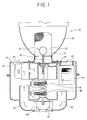
- the conventional electrodeless lighting system includes a microwave generating unit 10 installed inside a housing 50 and generating microwave energy; a power supply unit 40 applying power to the microwave generating unit 10; a waveguide 20 connected to the microwave generating unit 10 and transmitting the microwave energy generated in the microwave generating unit 10; a light emitting unit 30 forming plasma 20 and generating light by being excited by the microwave energy transmitted through the waveguide 20; and a cooling fan 60 installed at a certain side of the housing 50 and cooling the microwave generating unit 10 and the power supply unit 40.
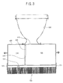
- the heat insulating wall 510 can be placed between the waveguide 200 and the magnetron 200, in that case, assembly can be performed after fabricating the heat insulating wall 510 separately, or the heat insulating wall 510 can be fabricated at a certain side surface of the waveguide 200 as one body.
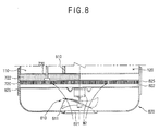
- the fan housing 820 is fixedly combined with the housing 500 by a connecting member 825, etc.
- the radiator 720 is placed in the air path.
- the radiator 720 can be fabricated as Figure 2 or 5. In Figure 8, the radiator 720 in Figure 5 is used.
Landscapes
- Physics & Mathematics (AREA)
- Electromagnetism (AREA)
- Engineering & Computer Science (AREA)
- Plasma & Fusion (AREA)
- Non-Portable Lighting Devices Or Systems Thereof (AREA)
- Arrangement Of Elements, Cooling, Sealing, Or The Like Of Lighting Devices (AREA)
- Circuit Arrangements For Discharge Lamps (AREA)
Abstract
Description
Claims (27)
- An electrodeless lighting system, comprising:a microwave generating unit for generating microwave energy;a light emitting unit connected to the microwave generating unit and emitting light by forming plasma by the microwave energy generated in the microwave generating unit;a housing having a first receiving space for receiving the microwave generating unit and sealed-combined with the light emitting unit;a heat exchanger installed at the outer surface of the microwave generating unit to absorb heat generated in the microwave generating unit;a radiator installed at the outer surface of the housing; anda heat transfer member at which one end is connected to the heat exchanger and the other end is connected to the radiator by penetrating the housing to transmit heat from the heat exchanger to the radiator.
- The system of claim 1, further comprising:a waveguide received in a second receiving space of the housing and transmitting microwave energy from the microwave generating unit to the light emitting unit.
- The system of claim 2, wherein a heat insulating wall is formed at the internal or the outer surface of the waveguide.
- The system of claim 2, wherein a heat insulating wall is formed at the internal and the outer surfaces of the waveguide.
- The system of claim 1, wherein the light emitting unit includes:a resonator cutting off microwave energy and passing light; anda bulb filled with materials forming plasma by microwave energy.
- The system of claim 1, wherein the heat exchanger and the heat transfer member are formed as one body.
- The system of claim 1, wherein the microwave generating unit is a magnetron.
- The system of claim 7, wherein the heat exchanger is a coil wound around the outer surface of an anode body of the magnetron.
- The system of claim 1, wherein the heat transfer member is a heat pipe.
- The system of claim 1, wherein the heat transfer member is a thermoelectric device.
- The system of claim 1, wherein the first receiving space has a heat insulating wall to insulate other units inside the housing from heat generated in the microwave generating unit.
- The system of claim 11, wherein the first receiving space is sealed by the heat insulating wall, the heat insulating wall has an opening formed for connecting an output of the microwave generating unit to the light emitting unit and a hole formed for an electric wire to apply power to the microwave generating unit.
- The system of claim 11, wherein the heat insulating wall is formed as one body with the housing.
- The system of claim 11, wherein the heat insulating wall is received in the housing and formed as one body with the waveguide transmitting microwave energy from the microwave generating unit to the light emitting unit.
- The system of claim 1, wherein the radiator is fixedly installed at the outer surface of the housing by a fixing member so as to have a certain distance from the housing.
- The system of claim 15, wherein the fixing member has a heat insulating characteristic.
- The system of claim 1, wherein a heat insulating member is interposed between the radiator and the outer surface of the housing, and the radiator is fixedly installed at the outer surface of the housing.
- The system of claim 1, wherein the radiator consists of plural radiating pins combined with the heat transfer member.
- The system of claim 1, wherein the section of the heat transfer member has a quadrilateral shape.
- The system of claim 1, further comprising:wherein the radiator is installed in the air path.a fan housing having an air inlet hole for air inflow, an air discharge hole for discharging air and an air path connected to the air inlet hole and the air discharge hole and fixedly installed at the outer surface of the housing;a fan installed in the air path to generate air flow in the air path;
- The system of claim 20, wherein the fan housing is combined with the housing by a connecting means with a distance from the housing.
- The system of claim 20, wherein the air path is formed so as to surround the outer surface of the housing.
- The system of claim 1, further comprising:the power supply unit received in a third receiving space formed inside the housing to apply power to the microwave generating unit.
- The system of claim 23, further comprising:a heat exchanger installed at the outer surface of the power unit to absorb heat generated in the power unit; anda heat transfer member at which one end is connected to the heat exchanger and the other end is connected to the radiator by penetrating the housing to transmit heat from the heat exchanger to the radiator.
- The system of claim 23, further comprising:wherein the radiator is installed in the air path.a fan housing having an air inlet hole for air inflow, an air discharge hole for discharging air and an air path connected to the air inlet hole and the air discharge hole and fixedly installed at the outer surface of the housing;a fan installed in the air path to generate air flow in the air path;
- The system of claim 25, wherein the fan housing is combined with the housing by a connecting means with a distance from the housing.
- The system of claim 25, wherein the air path is formed so as to surround the outer surface of the housing.
Applications Claiming Priority (4)
| Application Number | Priority Date | Filing Date | Title |
|---|---|---|---|
| KR10-2002-0004554A KR100414125B1 (en) | 2002-01-25 | 2002-01-25 | Cooling apparatus for microwave lighting system |
| KR2002004555 | 2002-01-25 | ||
| KR10-2002-0004555A KR100414126B1 (en) | 2002-01-25 | 2002-01-25 | Cooling apparatus for microwave lighting system |
| KR2002004554 | 2002-01-25 |
Publications (3)
| Publication Number | Publication Date |
|---|---|
| EP1335408A2 true EP1335408A2 (en) | 2003-08-13 |
| EP1335408A3 EP1335408A3 (en) | 2004-10-20 |
| EP1335408B1 EP1335408B1 (en) | 2007-11-07 |
Family
ID=27615778
Family Applications (1)
| Application Number | Title | Priority Date | Filing Date |
|---|---|---|---|
| EP02016899A Expired - Lifetime EP1335408B1 (en) | 2002-01-25 | 2002-07-31 | Electrodeless lighting system |
Country Status (5)
| Country | Link |
|---|---|
| US (1) | US6774571B2 (en) |
| EP (1) | EP1335408B1 (en) |
| JP (1) | JP2003217312A (en) |
| CN (1) | CN100377291C (en) |
| DE (1) | DE60223332T2 (en) |
Cited By (1)
| Publication number | Priority date | Publication date | Assignee | Title |
|---|---|---|---|---|
| WO2013050730A1 (en) * | 2011-10-07 | 2013-04-11 | Ceravision Limited | Microwave driven electrodeless lamp comprising magnetron without forced convective cooling |
Families Citing this family (14)
| Publication number | Priority date | Publication date | Assignee | Title |
|---|---|---|---|---|
| KR100442397B1 (en) * | 2002-01-17 | 2004-07-30 | 엘지전자 주식회사 | Structure for exciting discharge in plasma lighting system |
| EP1335408B1 (en) * | 2002-01-25 | 2007-11-07 | Lg Electronics Inc. | Electrodeless lighting system |
| KR100531804B1 (en) * | 2002-12-17 | 2005-12-02 | 엘지전자 주식회사 | Plasma lighting system |
| US7182484B2 (en) * | 2003-03-07 | 2007-02-27 | Fiberstars, Inc. | Light appliance and cooling arrangement |
| KR100631541B1 (en) * | 2004-10-26 | 2006-10-09 | 엘지전자 주식회사 | Street Light System Using Plasma |
| KR20060111044A (en) * | 2005-04-21 | 2006-10-26 | 엘지전자 주식회사 | Light reflector of electrodeless illuminator |
| US8229593B2 (en) * | 2005-10-03 | 2012-07-24 | International Business Machines Corporation | Document destruction management |
| JP2008204844A (en) * | 2007-02-21 | 2008-09-04 | Toyoda Gosei Co Ltd | Vehicular headlight |
| US8439534B1 (en) * | 2009-05-06 | 2013-05-14 | George Michael Roe | Mobile lighting apparatus |
| CN101968173A (en) * | 2010-08-21 | 2011-02-09 | 张誉耀 | Microwave sulfur lamp |
| KR101943321B1 (en) * | 2012-11-12 | 2019-01-29 | 엘지전자 주식회사 | Lighting apparatus |
| KR101557445B1 (en) * | 2014-05-12 | 2015-10-06 | 엘지전자 주식회사 | lighting system |
| EP3704732B1 (en) * | 2017-11-03 | 2025-03-05 | Excelitas Noblelight America LLC | Ultraviolet lamp systems and methods of operating the same |
| CN111261476A (en) * | 2018-11-30 | 2020-06-09 | 曾东荣 | Heat sink for microwave magnetron |
Family Cites Families (19)
| Publication number | Priority date | Publication date | Assignee | Title |
|---|---|---|---|---|
| US3369597A (en) * | 1965-06-18 | 1968-02-20 | Motorola Inc | Method and apparatus for heat conduction from a flat surface of a conductor on an electrical component |
| NL8400409A (en) * | 1984-02-09 | 1985-09-02 | Philips Nv | ELECTLESS LOW PRESSURE GAS DISCHARGE LAMP. |
| NL8500736A (en) * | 1985-03-14 | 1986-10-01 | Philips Nv | ELECTRESSLESS LOW PRESSURE DISCHARGE LAMP. |
| DE4445818A1 (en) * | 1994-12-21 | 1995-06-14 | Bernhard Hilpert | Computer housing suitable for applications in industry |
| US5866990A (en) * | 1996-01-26 | 1999-02-02 | Fusion Lighting, Inc. | Microwave lamp with multi-purpose rotary motor |
| JPH09284685A (en) * | 1996-04-17 | 1997-10-31 | Hitachi Ltd | Projection type liquid crystal display device |
| US6031333A (en) * | 1996-04-22 | 2000-02-29 | Fusion Lighting, Inc. | Compact microwave lamp having a tuning block and a dielectric located in a lamp cavity |
| DE29607354U1 (en) * | 1996-04-23 | 1996-07-11 | Brinkmann GmbH & Co. KG, 32683 Barntrup | Electrical device with an electrical power component to be cooled |
| US5655375A (en) * | 1996-06-24 | 1997-08-12 | Y.B.S. Enterprises, Inc. | Antenna mast-top mountable thermo-electrically cooled amplifier enclosure system |
| US5847517A (en) * | 1996-07-10 | 1998-12-08 | Fusion Lighting, Inc. | Method and apparatus for igniting electrodeless lamp with ferroelectric emission |
| US5786667A (en) * | 1996-08-09 | 1998-07-28 | Fusion Lighting, Inc. | Electrodeless lamp using separate microwave energy resonance modes for ignition and operation |
| US5731954A (en) * | 1996-08-22 | 1998-03-24 | Cheon; Kioan | Cooling system for computer |
| JPH10321039A (en) * | 1997-05-15 | 1998-12-04 | Matsushita Electron Corp | Microwave discharge lamp device |
| US5940270A (en) * | 1998-07-08 | 1999-08-17 | Puckett; John Christopher | Two-phase constant-pressure closed-loop water cooling system for a heat producing device |
| JP3174296B2 (en) * | 1998-07-15 | 2001-06-11 | 松下電子工業株式会社 | Microwave electrodeless discharge lamp device |
| CN1350698A (en) * | 1999-05-12 | 2002-05-22 | 熔化照明股份有限公司 | High brightness microwave lamp |
| KR20020093071A (en) * | 2000-04-26 | 2002-12-12 | 코넬 리서치 화운데이션,인크. | Lamp utilizing fiber for enhanced starting field |
| KR100396772B1 (en) * | 2001-02-02 | 2003-09-03 | 엘지전자 주식회사 | Microwave lighting system |
| EP1335408B1 (en) * | 2002-01-25 | 2007-11-07 | Lg Electronics Inc. | Electrodeless lighting system |
-
2002
- 2002-07-31 EP EP02016899A patent/EP1335408B1/en not_active Expired - Lifetime
- 2002-07-31 DE DE60223332T patent/DE60223332T2/en not_active Expired - Fee Related
- 2002-08-07 US US10/213,148 patent/US6774571B2/en not_active Expired - Lifetime
- 2002-08-19 JP JP2002237922A patent/JP2003217312A/en active Pending
- 2002-08-23 CN CNB021301654A patent/CN100377291C/en not_active Expired - Fee Related
Cited By (2)
| Publication number | Priority date | Publication date | Assignee | Title |
|---|---|---|---|---|
| WO2013050730A1 (en) * | 2011-10-07 | 2013-04-11 | Ceravision Limited | Microwave driven electrodeless lamp comprising magnetron without forced convective cooling |
| US9159520B2 (en) | 2011-10-07 | 2015-10-13 | Ceravision Limited | Microwave driven electrodeless lamp comprising magnetron without forced convective cooling |
Also Published As
| Publication number | Publication date |
|---|---|
| EP1335408B1 (en) | 2007-11-07 |
| US6774571B2 (en) | 2004-08-10 |
| US20030141828A1 (en) | 2003-07-31 |
| DE60223332D1 (en) | 2007-12-20 |
| CN1434478A (en) | 2003-08-06 |
| CN100377291C (en) | 2008-03-26 |
| JP2003217312A (en) | 2003-07-31 |
| DE60223332T2 (en) | 2008-02-28 |
| EP1335408A3 (en) | 2004-10-20 |
Similar Documents
| Publication | Publication Date | Title |
|---|---|---|
| US6774571B2 (en) | Electrodeless lighting system | |
| EP2721631B1 (en) | Electrodeless lamp | |
| US6680576B2 (en) | Lighting apparatus using microwave | |
| JP2004505429A (en) | Plasma lamp having dielectric waveguide and light emitting method thereof | |
| CN100349252C (en) | Electrodeless lighting system | |
| CN100459024C (en) | Cooling apparatus of plasma lighting system | |
| EP1304725A2 (en) | Electrodeless discharge lamp using microwave energy | |
| US6608443B1 (en) | Lighting apparatus using microwave energy | |
| US6351087B1 (en) | Microwave electrodeless discharge lamp apparatus | |
| US6744221B2 (en) | Electrodeless lighting system and bulb therefor | |
| US6633130B2 (en) | Cooling system of lighting apparatus using microwave energy | |
| US7397173B2 (en) | Lighting apparatus using microwave energy | |
| JPH09245746A (en) | Microwave discharge light source device | |
| KR100414125B1 (en) | Cooling apparatus for microwave lighting system | |
| KR100414126B1 (en) | Cooling apparatus for microwave lighting system | |
| KR100451231B1 (en) | Cooling apparatus for magnetron and plasma lighting apparatus with that | |
| KR100451230B1 (en) | Cooling apparatus for magnetron and plasma lighting apparatus with that | |
| KR100739191B1 (en) | Electrodeless lighting equipment | |
| JP2003346720A (en) | High pressure discharge lamp and light source unit |
Legal Events
| Date | Code | Title | Description |
|---|---|---|---|
| PUAI | Public reference made under article 153(3) epc to a published international application that has entered the european phase |
Free format text: ORIGINAL CODE: 0009012 |
|
| AK | Designated contracting states |
Designated state(s): AT BE BG CH CY CZ DE DK EE ES FI FR GB GR IE IT LI LU MC NL PT SE SK TR |
|
| AX | Request for extension of the european patent |
Extension state: AL LT LV MK RO SI |
|
| PUAL | Search report despatched |
Free format text: ORIGINAL CODE: 0009013 |
|
| AK | Designated contracting states |
Kind code of ref document: A3 Designated state(s): AT BE BG CH CY CZ DE DK EE ES FI FR GB GR IE IT LI LU MC NL PT SE SK TR |
|
| AX | Request for extension of the european patent |
Extension state: AL LT LV MK RO SI |
|
| RIC1 | Information provided on ipc code assigned before grant |
Ipc: 7H 01J 65/04 A Ipc: 7H 01J 61/52 B Ipc: 7H 05K 7/20 B Ipc: 7H 01J 23/00 B |
|
| 17P | Request for examination filed |
Effective date: 20050324 |
|
| 17Q | First examination report despatched |
Effective date: 20050428 |
|
| AKX | Designation fees paid |
Designated state(s): DE FR GB IT SE |
|
| GRAP | Despatch of communication of intention to grant a patent |
Free format text: ORIGINAL CODE: EPIDOSNIGR1 |
|
| GRAS | Grant fee paid |
Free format text: ORIGINAL CODE: EPIDOSNIGR3 |
|
| GRAA | (expected) grant |
Free format text: ORIGINAL CODE: 0009210 |
|
| AK | Designated contracting states |
Kind code of ref document: B1 Designated state(s): DE FR GB IT SE |
|
| REG | Reference to a national code |
Ref country code: GB Ref legal event code: FG4D |
|
| REF | Corresponds to: |
Ref document number: 60223332 Country of ref document: DE Date of ref document: 20071220 Kind code of ref document: P |
|
| REG | Reference to a national code |
Ref country code: SE Ref legal event code: TRGR |
|
| ET | Fr: translation filed | ||
| PLBE | No opposition filed within time limit |
Free format text: ORIGINAL CODE: 0009261 |
|
| STAA | Information on the status of an ep patent application or granted ep patent |
Free format text: STATUS: NO OPPOSITION FILED WITHIN TIME LIMIT |
|
| 26N | No opposition filed |
Effective date: 20080808 |
|
| EUG | Se: european patent has lapsed | ||
| PG25 | Lapsed in a contracting state [announced via postgrant information from national office to epo] |
Ref country code: IT Free format text: LAPSE BECAUSE OF NON-PAYMENT OF DUE FEES Effective date: 20080731 |
|
| PGFP | Annual fee paid to national office [announced via postgrant information from national office to epo] |
Ref country code: FR Payment date: 20090710 Year of fee payment: 8 |
|
| PGFP | Annual fee paid to national office [announced via postgrant information from national office to epo] |
Ref country code: DE Payment date: 20090723 Year of fee payment: 8 Ref country code: GB Payment date: 20090729 Year of fee payment: 8 |
|
| PG25 | Lapsed in a contracting state [announced via postgrant information from national office to epo] |
Ref country code: SE Free format text: LAPSE BECAUSE OF NON-PAYMENT OF DUE FEES Effective date: 20080801 |
|
| GBPC | Gb: european patent ceased through non-payment of renewal fee |
Effective date: 20100731 |
|
| REG | Reference to a national code |
Ref country code: FR Ref legal event code: ST Effective date: 20110331 |
|
| PG25 | Lapsed in a contracting state [announced via postgrant information from national office to epo] |
Ref country code: DE Free format text: LAPSE BECAUSE OF NON-PAYMENT OF DUE FEES Effective date: 20110201 |
|
| REG | Reference to a national code |
Ref country code: DE Ref legal event code: R119 Ref document number: 60223332 Country of ref document: DE Effective date: 20110201 |
|
| PG25 | Lapsed in a contracting state [announced via postgrant information from national office to epo] |
Ref country code: FR Free format text: LAPSE BECAUSE OF NON-PAYMENT OF DUE FEES Effective date: 20100802 |
|
| PG25 | Lapsed in a contracting state [announced via postgrant information from national office to epo] |
Ref country code: GB Free format text: LAPSE BECAUSE OF NON-PAYMENT OF DUE FEES Effective date: 20100731 |