EP1335396A1 - Collision detection apparatus designed to minimize contact chatter - Google Patents
Collision detection apparatus designed to minimize contact chatter Download PDFInfo
- Publication number
- EP1335396A1 EP1335396A1 EP03002394A EP03002394A EP1335396A1 EP 1335396 A1 EP1335396 A1 EP 1335396A1 EP 03002394 A EP03002394 A EP 03002394A EP 03002394 A EP03002394 A EP 03002394A EP 1335396 A1 EP1335396 A1 EP 1335396A1
- Authority
- EP
- European Patent Office
- Prior art keywords
- contact
- spring
- leaf spring
- detecting apparatus
- moving member
- Prior art date
- Legal status (The legal status is an assumption and is not a legal conclusion. Google has not performed a legal analysis and makes no representation as to the accuracy of the status listed.)
- Withdrawn
Links
- 238000001514 detection method Methods 0.000 title description 4
- 230000003247 decreasing effect Effects 0.000 claims abstract description 14
- 230000002787 reinforcement Effects 0.000 claims description 3
- 230000005484 gravity Effects 0.000 description 3
- 230000004048 modification Effects 0.000 description 2
- 238000012986 modification Methods 0.000 description 2
- 125000006850 spacer group Chemical group 0.000 description 2
- 238000005452 bending Methods 0.000 description 1
- 230000007613 environmental effect Effects 0.000 description 1
Images

Classifications
-
- H—ELECTRICITY
- H01—ELECTRIC ELEMENTS
- H01H—ELECTRIC SWITCHES; RELAYS; SELECTORS; EMERGENCY PROTECTIVE DEVICES
- H01H1/00—Contacts
- H01H1/50—Means for increasing contact pressure, preventing vibration of contacts, holding contacts together after engagement, or biasing contacts to the open position
-
- H—ELECTRICITY
- H01—ELECTRIC ELEMENTS
- H01H—ELECTRIC SWITCHES; RELAYS; SELECTORS; EMERGENCY PROTECTIVE DEVICES
- H01H1/00—Contacts
- H01H1/12—Contacts characterised by the manner in which co-operating contacts engage
- H01H1/14—Contacts characterised by the manner in which co-operating contacts engage by abutting
- H01H1/24—Contacts characterised by the manner in which co-operating contacts engage by abutting with resilient mounting
- H01H1/26—Contacts characterised by the manner in which co-operating contacts engage by abutting with resilient mounting with spring blade support
-
- H—ELECTRICITY
- H01—ELECTRIC ELEMENTS
- H01H—ELECTRIC SWITCHES; RELAYS; SELECTORS; EMERGENCY PROTECTIVE DEVICES
- H01H35/00—Switches operated by change of a physical condition
- H01H35/14—Switches operated by change of acceleration, e.g. by shock or vibration, inertia switch
Definitions
- the present invention relates generally to a collision detection apparatus working to detect a mechanical impact more than a preset level upon an accidental vehicle collision, and more particularly to an improved structure of such a collision detection apparatus designed to minimize contact chatter in the apparatus.
- Japanese Patent No. 3191724 (U.S.P. No. 5,898,144, issued on April 27, 1999, assigned to the same assignee as that of this application) discloses a conventional collision detector which, as shown in Fig. 5, consists of a rotor 3, a first contact spring 7, and a second contact spring 8.
- the rotor 3 is responsive to an impact arising from a vehicle crash to rotate and urge the first contact spring 7 into contact with the second contact spring 8, thereby producing an electrical signal.
- the second contact spring 8 is made up of two leaf springs in order to increase an elastic pressure required to secure the stability of contact between the first and second contact springs 7 and 8 without contact chatter.
- vehicle collision detectors are installed in a front portion of a vehicle body (e.g., a front fender) for the purpose of early detection of a vehicle collision.
- vehicle collision detectors are placed in an environmental condition where they undergo a great deceleration and still have a difficulty in eliminating the contact chatter completely.
- a collision detecting apparatus which may be employed in actuating a safety restraint system such as an air bag upon a vehicle crash.
- the collision detecting apparatus comprises: (a) a moving member moving when subjected to an impact of more than a given level arising from a collision with another object; and (b) a first and a second contact member which are disposed on a mount base and extend with a given gap therebetween. The first contact member is brought by the moving member into contact with the second contact member to produce an electrical signal indicative thereof when the moving member undergoes the impact of more than the given level.
- At least one of the first and second contact members is made of a leaf spring which has a length including a base portion secured on the mount base and a contact portion for establishing a contact with the other of the first and second contact members.
- the base portion is smaller in width than the contact portion. This results in a decrease in weight of the contact portion, thereby having the contact portion remote from the mount base less susceptible to vibrations to avoid contact chatter.
- the at least one of the first and second contact members is decreased in width gradually from the base portion to the contact portion.
- the at least one of the first and second contact members may alternatively be decreased in width in a stepwise fashion from the base portion to the contact portion.
- the leaf spring may have a reinforcement rib formed thereon to compensate for a loss in rigidity resulting from the decrease in width of the contact portion.
- the second contact member is made up of a first and a second leaf spring.
- the first leaf spring works to establish the contact with the first contact member when pressed by the moving member.
- the second leaf spring works to produce an elastic pressure to urge the first leaf spring against the first contact member when the first contact member is pressed by the moving member and makes the contact with the second contact member.
- a first point of the contact of the first contact member with the second contact member established by the moving member and a second point of contact of the moving member with the first contact member may be located at the same interval away from the mount base.
- the first point may coincide spatially with the second point.
- a collision detector 1 according to the first embodiment of the invention which works to detect a mechanical impact acting thereon.
- the following discussion will refer to an example in which the collision detector 1 is installed in an automotive vehicle to deploy an air bag upon a vehicle crash.
- the collision detector 1 consists essentially of a rotor 3, first and second contact springs 7 and 8, a weight 4, and a housing 6.
- the rotor 3 is installed within the housing 6 integrally with the weight 4.
- the center of gravity of the weight 4 is located eccentrically to an axis of rotation (i.e., a center shaft 2) of the rotor 3.
- the center shaft 2 is carried on an inner wall of the housing 6.
- the rotor 3 has installed thereon a cam 5 which works to close the first and second contact springs 7 and 8 upon occurrence of a vehicle collision.
- the first and second contact springs 7 and 8 are secured on a mount base 6a of the housing 6 and extend vertically, as viewed in the drawing, with a given contact gap therebetween.
- the first contact spring 7 is made of a single leaf spring and has an upper end abutting to a side surface of the cam 5 to provide a set spring load thereto which urges the rotor 3 elastically in a counterclockwise direction, as viewed in the drawing, to bring the weight 4 into constant engagement with an inner side wall 6b of the housing 6. This holds the rotor 3 from rotating in the clockwise direction when deceleration arising from mechanical vibrations during traveling of the detector-equipped vehicle or sudden braking is lower than a preselected level.
- the second contact spring 8 is made up of two springs: a first leaf spring 8A and a second leaf spring 8B.
- the first leaf spring 8A has an upper end thereof which elastically abuts to a stopper 9 formed on the housing 6.
- the first leaf spring 8A has a protrusion or contact 8a which makes an electrical contact with the first contact spring 7 when the first contact spring 7 is pushed by the cam 5 moved by rotation of the rotor 3.
- the contact 8a is formed by bending a portion of the first leaf spring 8A to a triangular shape and located at a given interval away from the contact spring 7.
- the second leaf spring 8B extends behind the back of the first leaf spring 8A. Specifically, the first leaf spring 8A is located between the second leaf spring 8B and the first contact spring 7. The second leaf spring 8B has an upper end abutting to the upper end of the first leaf spring 8A elastically to urge it against the stopper 9.
- a spacer 10 is disposed on the mount base 6a of the housing 6 between lower ends of the first and second leaf springs 8A and 8B to maintain a constant gap between the lower ends of the first and second leaf springs 8A and 8B.
- the lower ends of the first and second leaf springs 8A and 8B may alternatively be secured on the mount base 6b fixedly with the constant gap therebetween without use of the spacer 10.
- the first and second contact springs 7 and 8 connect with contact terminals which are joined electrically to, for example, a printed circuit board (not shown) mounted in the housing 6 and work to connect or interrupt an electrical circuit path on the printed circuit board.
- the printed circuit board is connected to an ECU (Electronic Control Unit).
- ECU Electronic Control Unit
- the ECU is responsive to input of the signal to actuate, for example, a passenger restraint device such as an air bag.
- the detector-equipped vehicle collides with, for example, another vehicle and undergoes a mechanical impact or deceleration of force exceeding a preselected threshold level, it will cause the moment to act on the center of gravity of the weight 4, so that the rotor 3 rotates about the center shaft 2 in the clockwise direction, as viewed in Fig. 1.
- the first contact spring 7 is urged elastically by the cam 5 to the left and hits on the contact 8a of the first leaf spring 8A of the second contact spring 8, thereby closing the electrical circuit path on the printed circuit board to provide the signal indicative thereof to the ECU.
- the ECU Upon in put of the signal, the ECU detects occurrence of the vehicle collision and deploys the air bag.
- the second contact spring 8 is, as described above, made up of the first and second leaf springs 8A and 8B which extend from the mount base 6a of the housing 6.
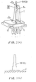
- the lower end of each of the first and second leaf springs 8A and 8B on the mount base 6a has, as clearly shown in Fig. 2(a), width W1 which is greater than width W2 of the upper end thereof.
- each of the first and second leaf springs 8A and 8B tapers off to the upper end, so that the weight of an upper portion thereof is smaller than that of a lower portion, thereby making the first and second leaf springs 8A and 8B less susceptible to vibration, thus suppressing the contact chatter.
- the decrease in weight of the first and second leaf springs 8A and 8B leads to a concern about decreasing of the elastic load acting on the contact 8a when it engages the first contact spring 7, but however, the upper portion of each of the first and second leaf springs 8A and 8B cantilevered on the base 6a of the housing 6 that is the greatest in inertia weight in an overall length thereof is decreased in weight, therefore, the decreasing of the elastic load on the contact 8a is smaller as compared with when the overall width of each of the first and second leaf springs 8A and 8B is decreased.
- the second contact spring 8 has a double walled structure made up of the first and second leaf springs 8A and 8B, thereby compensating for the decreasing of the elastic load on the contact 8a, thereby ensuring an electrical contact between the first and second contact springs 7 and 8.
- each of the first and second leaf springs 8A and 8B is, as can be seen from Fig. 2(a), preferably decreased from the lower end at least within a lower half thereof for decreasing the weight of the upper portion to have the first and second leaf springs 8A and 8B less susceptible to vibration.
- the width may, however, be decreased at a constant rate as a whole or in a stepwise fashion, as illustrated in Fig. 2(b).
- the collision detector 1 of the second embodiment will be described below.
- Fig. 3 illustrates the first and second contact springs 7 and 8 in the second embodiment.
- Each of the first and second leaf springs 8A and 8B of the second contact spring 8 has formed thereon a reinforcement rib 11 (only one is shown for the brevity of illustration) which serves to compensate for a loss in rigidity resulting from the decrease in width of the upper portion of each of the first and second leaf springs 8A and 8B. This ensures the elastic load on the contact 8a required to secure the stability of contact between the first and second contact springs 7 and 8.
- the rib 11 is made using, for example, a press.
- the rib 11 may alternatively be formed only one of the first and second leaf springs 8A and 8B.
- the first contact spring 7 may also be made to have the same structure as that of the second contact spring 8. Specifically, the first contact spring 7 may be increased in width from the lower to upper portion thereof either gradually or in a stepwise fashion
- the second contact spring 8 may alternatively be made of a single leaf spring or more than two leaf springs.
- the collision detector 1 is so designed that the deceleration acting thereon causes the rotor 3 to rotate about the center shaft 2, but however, may have a rod instead of the rotor 3 which reciprocates linearly to push the first contact spring 7 upon a vehicle crash.
- the collision detector 1 of the third embodiment will be described below with reference to Fig. 4.
- the same reference numbers as employed in the above embodiments refer to the same parts, and explanation thereof in detail will be omitted here.
- the collision detector 1 of this embodiment is so designed that a contact point X between the outer surface of the cam 5 and the first contact spring 7 coincides spatially with the contact 8a of the second contact spring 8.
- the contact point X and a contact point Y between the contact 8a and the first contact spring 7 are located at the same interval away from the surface of the base 6a of the housing 6 from which the first and second contact springs 7 and 8 extend. Accordingly, upon rotation of the rotor 3 by a vehicle collision, the cam 5 hits on the contact 8a through the first contact spring 7 to establish an electrical contact between the first and second contact springs 7 and 8.
- the first contact spring 7 When brought into contact with the contact 8a of the second contact spring 8, the first contact spring 7 is pressed by the cam 5 against the contact 8a, thereby suppressing mechanical vibrations of the first contact spring 7 on the contact 8a to avoid the contact chatter.
- the prior art structure as shown in Fig. 5, have the contact point X located at a great interval away from the contact 8a of the second contact spring 8. Therefore, when the first contact spring 7 is brought into contact with the second contact spring 8, the contact point X lies far away from the contact 8a, which causes the first contact spring 7 to vibrate about the contact point X and the second contact spring 8 to also vibrate about the point Z of contact with the stopper 9, thus resulting in the contact chatter between the first contact spring 7 and the contact 8a of the second contact spring 8.
- the contact point X in this embodiment as described above, lies in coincidence with the contact 8a, thus eliminating such a drawback.
- the contact point X is not always necessary to coincide exactly with the contact 8a of the second contact spring 8, but may be located slightly above the contact 8a if it falls within a production tolerance. If the contact point X lies below the contact point Y between the first contact spring 7 and the contact 8a of the second contact spring 8, it may cause the cam 5 to get over the contact 8 upward upon a further rotation of the rotor 3 after the first contact spring 7 hits on the contact 8a, thereby holding the cam 5 undesirably from returning back to its original position. In order to avoid this problem, the contact point X is preferably located at least above the contact 8a of the second contact spring 8 to decrease the torque required for the cam 5 to get over the contact 8 and return back to the original position thereof greatly.
Landscapes
- Switches Operated By Changes In Physical Conditions (AREA)
Abstract
A collision detecting apparatus (1) is provided which consists of
a rotor (3) and a first (7) and a second (8) contact spring. Upon collision, the
rotor pushes the first contact spring to establish an electrical
contact with the second contact spring. At least one of the first and
second contact member is decreased in width from a base portion
secured on a mount base to a contact portion, thereby decreasing
the weight of the contact portion to avoid the contact chatter.
Description
- The present invention relates generally to a collision detection apparatus working to detect a mechanical impact more than a preset level upon an accidental vehicle collision, and more particularly to an improved structure of such a collision detection apparatus designed to minimize contact chatter in the apparatus.
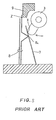
- Japanese Patent No. 3191724 (U.S.P. No. 5,898,144, issued on April 27, 1999, assigned to the same assignee as that of this application) discloses a conventional collision detector which, as shown in Fig. 5, consists of a
rotor 3, afirst contact spring 7, and asecond contact spring 8. Therotor 3 is responsive to an impact arising from a vehicle crash to rotate and urge thefirst contact spring 7 into contact with thesecond contact spring 8, thereby producing an electrical signal. Thesecond contact spring 8 is made up of two leaf springs in order to increase an elastic pressure required to secure the stability of contact between the first andsecond contact springs - Usually, most of vehicle collision detectors are installed in a front portion of a vehicle body (e.g., a front fender) for the purpose of early detection of a vehicle collision. Specifically, the vehicle collision detectors are placed in an environmental condition where they undergo a great deceleration and still have a difficulty in eliminating the contact chatter completely.
- It is therefore a principal object of the invention to avoid the disadvantages of the prior art.
- It is another object of the invention to provide a collision detecting apparatus which is designed to secure the stability of an electrical contact in the apparatus without any contact chatter.
- According to one aspect of the invention, there is provided a collision detecting apparatus which may be employed in actuating a safety restraint system such as an air bag upon a vehicle crash. The collision detecting apparatus comprises: (a) a moving member moving when subjected to an impact of more than a given level arising from a collision with another object; and (b) a first and a second contact member which are disposed on a mount base and extend with a given gap therebetween. The first contact member is brought by the moving member into contact with the second contact member to produce an electrical signal indicative thereof when the moving member undergoes the impact of more than the given level. At least one of the first and second contact members is made of a leaf spring which has a length including a base portion secured on the mount base and a contact portion for establishing a contact with the other of the first and second contact members. The base portion is smaller in width than the contact portion. This results in a decrease in weight of the contact portion, thereby having the contact portion remote from the mount base less susceptible to vibrations to avoid contact chatter.
- In the preferred mode of the invention, the at least one of the first and second contact members is decreased in width gradually from the base portion to the contact portion.
- The at least one of the first and second contact members may alternatively be decreased in width in a stepwise fashion from the base portion to the contact portion.
- The leaf spring may have a reinforcement rib formed thereon to compensate for a loss in rigidity resulting from the decrease in width of the contact portion.
- The second contact member is made up of a first and a second leaf spring. The first leaf spring works to establish the contact with the first contact member when pressed by the moving member. The second leaf spring works to produce an elastic pressure to urge the first leaf spring against the first contact member when the first contact member is pressed by the moving member and makes the contact with the second contact member.
- A first point of the contact of the first contact member with the second contact member established by the moving member and a second point of contact of the moving member with the first contact member may be located at the same interval away from the mount base. In other words, the first point may coincide spatially with the second point. When brought into contact with the second contact member, the first contact member is pressed by the moving member on the first point, thereby suppressing mechanical vibrations of the first contact member on the first point to avoid the contact chatter.
- The present invention will be understood more fully from the detailed description given hereinbelow and from the accompanying drawings of the preferred embodiments of the invention, which, however, should not be taken to limit the invention to the specific embodiments but are for the purpose of explanation and understanding only.
- In the drawings:
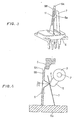
- Fig. 1 is a partially sectional view which shows a collision detector according to the first embodiment of the invention;
- Fig. 2(a) is a perspective view which shows a structure of contact springs installed within the collision detector of Fig. 1;
- Fig. 2(b) is a plane view which shows a modification of a contact spring which may be employed in the collision detector of Fig. 1;
- Fig. 3 is a perspective view which shows a second contact spring in the second embodiment;
- Fig. 4 is a partially sectional view which shows a collision detector according to the third embodiment; and
- Fig. 5 is a partially sectional view which shows a conventional collision detector.
-
- Referring to the drawings, wherein like reference numbers refer to like parts in several views, particularly to Fig. 1, there is shown a
collision detector 1 according to the first embodiment of the invention which works to detect a mechanical impact acting thereon. The following discussion will refer to an example in which thecollision detector 1 is installed in an automotive vehicle to deploy an air bag upon a vehicle crash. - The
collision detector 1 consists essentially of arotor 3, first andsecond contact springs housing 6. - The
rotor 3 is installed within thehousing 6 integrally with the weight 4. The center of gravity of the weight 4 is located eccentrically to an axis of rotation (i.e., a center shaft 2) of therotor 3. Thecenter shaft 2 is carried on an inner wall of thehousing 6. When the vehicle equipped with the collision detector 1 (which will be referred to as a detector-equipped vehicle below) undergoes sudden deceleration upon collision with any object, e.g., another vehicle, it will cause moment to act on the center of gravity of the weight 4 in accordance with the law of inertia, thereby causing therotor 3 to turn in a direction, as indicated by an arrow in the drawing, about thecenter shaft 2 along with the weight 4. - The
rotor 3 has installed thereon acam 5 which works to close the first andsecond contact springs second contact springs mount base 6a of thehousing 6 and extend vertically, as viewed in the drawing, with a given contact gap therebetween. - The
first contact spring 7 is made of a single leaf spring and has an upper end abutting to a side surface of thecam 5 to provide a set spring load thereto which urges therotor 3 elastically in a counterclockwise direction, as viewed in the drawing, to bring the weight 4 into constant engagement with aninner side wall 6b of thehousing 6. This holds therotor 3 from rotating in the clockwise direction when deceleration arising from mechanical vibrations during traveling of the detector-equipped vehicle or sudden braking is lower than a preselected level. - The
second contact spring 8 is made up of two springs: afirst leaf spring 8A and asecond leaf spring 8B. Thefirst leaf spring 8A has an upper end thereof which elastically abuts to astopper 9 formed on thehousing 6. Thefirst leaf spring 8A has a protrusion or contact 8a which makes an electrical contact with thefirst contact spring 7 when thefirst contact spring 7 is pushed by thecam 5 moved by rotation of therotor 3. Thecontact 8a is formed by bending a portion of thefirst leaf spring 8A to a triangular shape and located at a given interval away from thecontact spring 7. - The
second leaf spring 8B extends behind the back of thefirst leaf spring 8A. Specifically, thefirst leaf spring 8A is located between thesecond leaf spring 8B and thefirst contact spring 7. Thesecond leaf spring 8B has an upper end abutting to the upper end of thefirst leaf spring 8A elastically to urge it against thestopper 9. Aspacer 10 is disposed on themount base 6a of thehousing 6 between lower ends of the first andsecond leaf springs second leaf springs second leaf springs mount base 6b fixedly with the constant gap therebetween without use of thespacer 10. - The first and
second contact springs housing 6 and work to connect or interrupt an electrical circuit path on the printed circuit board. The printed circuit board is connected to an ECU (Electronic Control Unit). When thefirst contact spring 7 makes a contact with thesecond contact spring 8 to close the electrical circuit path on the printed circuit board, an electrical signal indicating such an event is produced and outputted to the ECU. The ECU is responsive to input of the signal to actuate, for example, a passenger restraint device such as an air bag. - In operation, when the detector-equipped vehicle collides with, for example, another vehicle and undergoes a mechanical impact or deceleration of force exceeding a preselected threshold level, it will cause the moment to act on the center of gravity of the weight 4, so that the
rotor 3 rotates about thecenter shaft 2 in the clockwise direction, as viewed in Fig. 1. Upon rotation of therotor 3, thefirst contact spring 7 is urged elastically by thecam 5 to the left and hits on thecontact 8a of thefirst leaf spring 8A of thesecond contact spring 8, thereby closing the electrical circuit path on the printed circuit board to provide the signal indicative thereof to the ECU. Upon in put of the signal, the ECU detects occurrence of the vehicle collision and deploys the air bag. - A geometrical figure of the
second contact spring 8 will be described below in detail which forms the feature of the invention. - The
second contact spring 8 is, as described above, made up of the first andsecond leaf springs mount base 6a of thehousing 6. The lower end of each of the first andsecond leaf springs mount base 6a has, as clearly shown in Fig. 2(a), width W1 which is greater than width W2 of the upper end thereof. Specifically, each of the first andsecond leaf springs second leaf springs second leaf springs contact 8a when it engages thefirst contact spring 7, but however, the upper portion of each of the first andsecond leaf springs base 6a of thehousing 6 that is the greatest in inertia weight in an overall length thereof is decreased in weight, therefore, the decreasing of the elastic load on thecontact 8a is smaller as compared with when the overall width of each of the first andsecond leaf springs - Moreover, the
second contact spring 8 has a double walled structure made up of the first andsecond leaf springs contact 8a, thereby ensuring an electrical contact between the first and second contact springs 7 and 8. - The width of each of the first and
second leaf springs second leaf springs - The
collision detector 1 of the second embodiment will be described below. - Fig. 3 illustrates the first and second contact springs 7 and 8 in the second embodiment. Each of the first and
second leaf springs second contact spring 8 has formed thereon a reinforcement rib 11 (only one is shown for the brevity of illustration) which serves to compensate for a loss in rigidity resulting from the decrease in width of the upper portion of each of the first andsecond leaf springs contact 8a required to secure the stability of contact between the first and second contact springs 7 and 8. Therib 11 is made using, for example, a press. - The
rib 11 may alternatively be formed only one of the first andsecond leaf springs - The
first contact spring 7 may also be made to have the same structure as that of thesecond contact spring 8. Specifically, thefirst contact spring 7 may be increased in width from the lower to upper portion thereof either gradually or in a stepwise fashion - The
second contact spring 8 may alternatively be made of a single leaf spring or more than two leaf springs. - The
collision detector 1 is so designed that the deceleration acting thereon causes therotor 3 to rotate about thecenter shaft 2, but however, may have a rod instead of therotor 3 which reciprocates linearly to push thefirst contact spring 7 upon a vehicle crash. - The
collision detector 1 of the third embodiment will be described below with reference to Fig. 4. The same reference numbers as employed in the above embodiments refer to the same parts, and explanation thereof in detail will be omitted here. - The
collision detector 1 of this embodiment is so designed that a contact point X between the outer surface of thecam 5 and thefirst contact spring 7 coincides spatially with thecontact 8a of thesecond contact spring 8. In other words, the contact point X and a contact point Y between thecontact 8a and thefirst contact spring 7 are located at the same interval away from the surface of thebase 6a of thehousing 6 from which the first and second contact springs 7 and 8 extend. Accordingly, upon rotation of therotor 3 by a vehicle collision, thecam 5 hits on thecontact 8a through thefirst contact spring 7 to establish an electrical contact between the first and second contact springs 7 and 8. When brought into contact with thecontact 8a of thesecond contact spring 8, thefirst contact spring 7 is pressed by thecam 5 against thecontact 8a, thereby suppressing mechanical vibrations of thefirst contact spring 7 on thecontact 8a to avoid the contact chatter. The prior art structure, as shown in Fig. 5, have the contact point X located at a great interval away from thecontact 8a of thesecond contact spring 8. Therefore, when thefirst contact spring 7 is brought into contact with thesecond contact spring 8, the contact point X lies far away from thecontact 8a, which causes thefirst contact spring 7 to vibrate about the contact point X and thesecond contact spring 8 to also vibrate about the point Z of contact with thestopper 9, thus resulting in the contact chatter between thefirst contact spring 7 and thecontact 8a of thesecond contact spring 8. The contact point X in this embodiment, as described above, lies in coincidence with thecontact 8a, thus eliminating such a drawback. - The contact point X is not always necessary to coincide exactly with the
contact 8a of thesecond contact spring 8, but may be located slightly above thecontact 8a if it falls within a production tolerance. If the contact point X lies below the contact point Y between thefirst contact spring 7 and thecontact 8a of thesecond contact spring 8, it may cause thecam 5 to get over thecontact 8 upward upon a further rotation of therotor 3 after thefirst contact spring 7 hits on thecontact 8a, thereby holding thecam 5 undesirably from returning back to its original position. In order to avoid this problem, the contact point X is preferably located at least above thecontact 8a of thesecond contact spring 8 to decrease the torque required for thecam 5 to get over thecontact 8 and return back to the original position thereof greatly. - While the present invention has been disclosed in terms of the preferred embodiments in order to facilitate better understanding thereof, it should be appreciated that the invention can be embodied in various ways without departing from the principle of the invention. Therefore, the invention should be understood to include all possible embodiments and modifications to the shown embodiments which can be embodied without departing from the principle of the invention as set forth in the appended claims.
Claims (7)
- A collision detecting apparatus comprising:a moving member moving when subjected to an impact of more than a given level arising from a collision with another object; anda first and a second contact member which are disposed on a mount base and extend with a given gap therebetween, said first contact member being brought by said moving member into contact with said second contact member to produce an electrical signal indicative thereof when said moving member undergoes the impact of more than the given level, at least one of said first and second contact members being made of a leaf spring which has a length including a base portion secured on the mount base and a contact portion for establishing a contact with the other of said first and second contact members, the base portion being smaller in width than the contact portion.
- A collision detecting apparatus as set forth in claim 1, wherein the at least one of said first and second contact members is decreased in width gradually from the base portion to the contact portion.
- A collision detecting apparatus as set forth in claim 1, wherein the at least one of said first and second contact members is decreased in width in a stepwise fashion from the base portion to the contact portion.
- A collision detecting apparatus as set forth in claim 1, wherein the leaf spring has a reinforcement rib formed thereon.
- A collision detecting apparatus as set forth in claim 1, wherein said second contact member is made up of a first and a second leaf spring, the first leaf spring working to establish the contact with the first contact member when pressed by said moving member, the second leaf spring working to produce an elastic pressure to urge the first leaf spring against said first contact member when said first contact member is pressed by said moving member and makes the contact with the second contact member.
- A collision detecting apparatus as set forth in claim 1, wherein a point of the contact of said first contact member with said second contact member established by said moving member and a point of contact of said moving member with the first contact member are located at the same interval away from the mount base.
- A collision detecting apparatus as set forth in claim 1, wherein a point of the contact of said first contact member with said second contact member established by said moving member coincides spatially with a point of contact of said moving member with the first contact member.
Applications Claiming Priority (4)
| Application Number | Priority Date | Filing Date | Title |
|---|---|---|---|
| JP2002030982A JP2003232804A (en) | 2002-02-07 | 2002-02-07 | Collision detection device |
| JP2002030982 | 2002-02-07 | ||
| JP2002031026A JP2003234051A (en) | 2002-02-07 | 2002-02-07 | Collision detection device |
| JP2002031026 | 2002-02-07 |
Publications (1)
| Publication Number | Publication Date |
|---|---|
| EP1335396A1 true EP1335396A1 (en) | 2003-08-13 |
Family
ID=27615744
Family Applications (1)
| Application Number | Title | Priority Date | Filing Date |
|---|---|---|---|
| EP03002394A Withdrawn EP1335396A1 (en) | 2002-02-07 | 2003-02-04 | Collision detection apparatus designed to minimize contact chatter |
Country Status (2)
| Country | Link |
|---|---|
| US (1) | US6717078B2 (en) |
| EP (1) | EP1335396A1 (en) |
Families Citing this family (4)
| Publication number | Priority date | Publication date | Assignee | Title |
|---|---|---|---|---|
| JP4200827B2 (en) * | 2003-06-20 | 2008-12-24 | 株式会社デンソー | Impact detection device |
| US7093886B2 (en) * | 2004-12-17 | 2006-08-22 | Benteler Automotive Corporation | Vehicle door beam with reinforced tab and method for making the same |
| JP5340892B2 (en) * | 2009-11-20 | 2013-11-13 | Idec株式会社 | Operation switch |
| CH704380A2 (en) * | 2011-01-24 | 2012-07-31 | Polycontact Ag | Switching arrangement for a buckle. |
Citations (6)
| Publication number | Priority date | Publication date | Assignee | Title |
|---|---|---|---|---|
| US2120980A (en) * | 1936-02-26 | 1938-06-21 | Associated Electric Lab Inc | Contact spring |
| FR1415375A (en) * | 1963-12-03 | 1965-10-22 | Hawker Siddeley Dynamics Ltd | Further development of electrical contactors |
| DE2058864A1 (en) * | 1970-11-30 | 1972-05-31 | Siemens Ag | Contact spring set |
| GB2128410A (en) * | 1982-10-07 | 1984-04-26 | Gen Electric Co Plc | Contact lever springs |
| US5034580A (en) * | 1989-06-01 | 1991-07-23 | Nippon Seiko Kabushiki Kaisha | Collision sensor |
| US5898144A (en) * | 1997-04-25 | 1999-04-27 | Denso Corporation | Anti-chattering contact structure and collision detecting apparatus using the same |
Family Cites Families (4)
| Publication number | Priority date | Publication date | Assignee | Title |
|---|---|---|---|---|
| US5856645A (en) * | 1987-03-02 | 1999-01-05 | Norton; Peter | Crash sensing switch |
| JPH03191724A (en) | 1989-12-18 | 1991-08-21 | Nisshoku Corp | Method for feeding water to plant on normal face |
| US6093897A (en) * | 1996-07-30 | 2000-07-25 | Denso Corporation | Collision detection device having eccentric mass and inertial mass |
| JPH1186699A (en) * | 1997-09-02 | 1999-03-30 | Denso Corp | Tilt detector |
-
2003
- 2003-02-04 EP EP03002394A patent/EP1335396A1/en not_active Withdrawn
- 2003-02-05 US US10/358,358 patent/US6717078B2/en not_active Expired - Fee Related
Patent Citations (6)
| Publication number | Priority date | Publication date | Assignee | Title |
|---|---|---|---|---|
| US2120980A (en) * | 1936-02-26 | 1938-06-21 | Associated Electric Lab Inc | Contact spring |
| FR1415375A (en) * | 1963-12-03 | 1965-10-22 | Hawker Siddeley Dynamics Ltd | Further development of electrical contactors |
| DE2058864A1 (en) * | 1970-11-30 | 1972-05-31 | Siemens Ag | Contact spring set |
| GB2128410A (en) * | 1982-10-07 | 1984-04-26 | Gen Electric Co Plc | Contact lever springs |
| US5034580A (en) * | 1989-06-01 | 1991-07-23 | Nippon Seiko Kabushiki Kaisha | Collision sensor |
| US5898144A (en) * | 1997-04-25 | 1999-04-27 | Denso Corporation | Anti-chattering contact structure and collision detecting apparatus using the same |
Also Published As
| Publication number | Publication date |
|---|---|
| US6717078B2 (en) | 2004-04-06 |
| US20030146078A1 (en) | 2003-08-07 |
Similar Documents
| Publication | Publication Date | Title |
|---|---|---|
| WO1990001789A1 (en) | Gas damped crash sensor | |
| EP0511556B1 (en) | Crash sensor | |
| WO2007024363A1 (en) | A fastener integrated sensor | |
| US6717078B2 (en) | Collision detection apparatus designed to minimize contact chatter | |
| EP1086478B1 (en) | Roll-over shunt sensor | |
| US5141193A (en) | Mounting system for a deceleration sensor | |
| EP0359288B1 (en) | Collision detecting device for motor vehicle | |
| US6512310B1 (en) | Electro-mechanical impact detecting device for vehicles | |
| US6142007A (en) | Shock sensor | |
| EP1489638B1 (en) | Collision impact detector for use in automotive vehicle | |
| JP3175557B2 (en) | Bidirectional shock sensor | |
| KR100456568B1 (en) | Automobile collision sensor united with sensor for sensing the amount of collision | |
| EP1271592B1 (en) | Deceleration impact detector for use in automotive vehicle | |
| JP2664356B2 (en) | Release device for vehicle occupant restraint | |
| JP2003232804A (en) | Collision detection device | |
| KR100422534B1 (en) | crash sensor for vehicle | |
| KR100387825B1 (en) | A Impact Sensing Sensor of Air-Bag | |
| JP4049532B2 (en) | Collision detection device | |
| JP4459316B2 (en) | Collision detection device | |
| JPH0740803A (en) | Deceleration sensor | |
| JPH02238368A (en) | Acceleration sensor | |
| JP2551879Y2 (en) | Impact sensor | |
| KR100448809B1 (en) | impact sensor of air bag | |
| JPH07294551A (en) | Acceleration sensor | |
| GB2234618A (en) | Mounting system for a deceleration sensor |
Legal Events
| Date | Code | Title | Description |
|---|---|---|---|
| PUAI | Public reference made under article 153(3) epc to a published international application that has entered the european phase |
Free format text: ORIGINAL CODE: 0009012 |
|
| AK | Designated contracting states |
Designated state(s): AT BE BG CH CY CZ DE DK EE ES FI FR GB GR HU IE IT LI LU MC NL PT SE SI SK TR |
|
| AX | Request for extension of the european patent |
Extension state: AL LT LV MK RO |
|
| 17P | Request for examination filed |
Effective date: 20030807 |
|
| 17Q | First examination report despatched |
Effective date: 20030924 |
|
| AKX | Designation fees paid |
Designated state(s): DE FR GB |
|
| STAA | Information on the status of an ep patent application or granted ep patent |
Free format text: STATUS: THE APPLICATION IS DEEMED TO BE WITHDRAWN |
|
| 18D | Application deemed to be withdrawn |
Effective date: 20050729 |