EP1335191A1 - Movable-magnet type meter and meter device using this movable-magnet type meter - Google Patents
Movable-magnet type meter and meter device using this movable-magnet type meter Download PDFInfo
- Publication number
- EP1335191A1 EP1335191A1 EP20010976754 EP01976754A EP1335191A1 EP 1335191 A1 EP1335191 A1 EP 1335191A1 EP 20010976754 EP20010976754 EP 20010976754 EP 01976754 A EP01976754 A EP 01976754A EP 1335191 A1 EP1335191 A1 EP 1335191A1
- Authority
- EP
- European Patent Office
- Prior art keywords
- rotor magnet
- magnet type
- movable magnet
- pointer
- movable
- Prior art date
- Legal status (The legal status is an assumption and is not a legal conclusion. Google has not performed a legal analysis and makes no representation as to the accuracy of the status listed.)
- Withdrawn
Links
Images




Classifications
-
- G—PHYSICS
- G01—MEASURING; TESTING
- G01D—MEASURING NOT SPECIALLY ADAPTED FOR A SPECIFIC VARIABLE; ARRANGEMENTS FOR MEASURING TWO OR MORE VARIABLES NOT COVERED IN A SINGLE OTHER SUBCLASS; TARIFF METERING APPARATUS; MEASURING OR TESTING NOT OTHERWISE PROVIDED FOR
- G01D13/00—Component parts of indicators for measuring arrangements not specially adapted for a specific variable
- G01D13/22—Pointers, e.g. settable pointer
-
- G—PHYSICS
- G01—MEASURING; TESTING
- G01R—MEASURING ELECTRIC VARIABLES; MEASURING MAGNETIC VARIABLES
- G01R7/00—Instruments capable of converting two or more currents or voltages into a single mechanical displacement
- G01R7/04—Instruments capable of converting two or more currents or voltages into a single mechanical displacement for forming a quotient
- G01R7/06—Instruments capable of converting two or more currents or voltages into a single mechanical displacement for forming a quotient moving-iron type
-
- H—ELECTRICITY
- H02—GENERATION; CONVERSION OR DISTRIBUTION OF ELECTRIC POWER
- H02K—DYNAMO-ELECTRIC MACHINES
- H02K21/00—Synchronous motors having permanent magnets; Synchronous generators having permanent magnets
- H02K21/12—Synchronous motors having permanent magnets; Synchronous generators having permanent magnets with stationary armatures and rotating magnets
- H02K21/14—Synchronous motors having permanent magnets; Synchronous generators having permanent magnets with stationary armatures and rotating magnets with magnets rotating within the armatures
-
- H—ELECTRICITY
- H02—GENERATION; CONVERSION OR DISTRIBUTION OF ELECTRIC POWER
- H02K—DYNAMO-ELECTRIC MACHINES
- H02K7/00—Arrangements for handling mechanical energy structurally associated with dynamo-electric machines, e.g. structural association with mechanical driving motors or auxiliary dynamo-electric machines
- H02K7/10—Structural association with clutches, brakes, gears, pulleys or mechanical starters
- H02K7/116—Structural association with clutches, brakes, gears, pulleys or mechanical starters with gears
Definitions
- the present invention relates to a movable magnet type instrument for operating a pointer and an instrument device using this movable magnet type instrument.
- the movable magnet type instrument of a crossing coil type is generally known as an instrument main body applied to an instrument device for a vehicle.
- a movable magnet type instrument is also called as an air core movement, and a rotor magnet magnetized by two poles of N and S poles is stored into a space formed in a housing.
- a rotor shaft fixed to the rotor magnet is pivoted by the housing. Further, one end of the rotor shaft is projected to the exterior of the housing, and the pointer is mounted.
- a pair of coils is orthogonally wound around the outer circumference of the housing.
- Driving signals having electrical angles different from each other, concretely, voltage signals of sine and cosine waves having different phases at the electrical angles are supplied to each coil.
- the rotor magnet is pivotally rotated by a synthetic magnetic field generated by each coil by this supply of the driving signal.
- the pointer can be angularly moved in accordance with a measuring amount by controlling the supply of the driving signal to each coil in accordance with a measured amount such as a vehicle speed, an engine rotation.
- a main portion of the movable magnet type instrument is covered with a shield case constructed by a magnetic material such as an iron nickel alloy such that no rotor magnet magnetized by the two poles is influenced by earth magnetism.
- the shield case constructed by the magnetic material such as the iron nickel alloy is required in consideration of magnetic interference with the rotor magnet, etc., magnetic efficiency, etc. Therefore, the number of parts cannot be reduced and it is difficult to reduce cost since the magnetic material such as the iron nickel alloy forming the shield case is expensive.
- the instrument device called a combination meter
- plural movable magnet type instruments mentioned above are particularly arranged. Therefore, the cost of the above movable magnet type instrument is further added to the cost of the instrument device as it is, so that the cost of the instrument device is increased.
- a main object of the present invention is to provide a movable magnet type instrument able to reduce cost and an instrument device using this movable magnet type instrument.
- the present invention resides in a movable magnet type instrument comprising a rotor magnet magnetized such that adjacent magnetic poles are poles different from each other; a pair of coils arranged around this rotor magnet and having winding central axes crossing each other without being perpendicular to each other; control means for processing an input signal based on a measured amount and supplying a driving signal mutually having a different electrical angle to each of said coils and rotating and operating said rotor magnet; and a pointer for rotating said rotor magnet as a driving source; wherein, when the number of magnetic poles of said rotor magnet is set to n and an acute angle formed by crossing said winding central axes is set to r, the acute angle r is set to an angle calculated by 360/2n (n is a multiple of 2 equal to or greater than 4).
- a protecting cover for protecting said coils and constructed by a nonmagnetic material is arranged.
- transmitting means for transmitting rotation of said rotor magnet to said pointer is arranged between said pointer and said rotor magnet, and said pointer is decelerated and rotated through said transmitting means in comparison with said rotor magnet.
- the present invention also resides in an instrument device using at least one movable magnet type instrument and comprising a rotor magnet magnetized by at least four magnetic poles or more, a pair of coils arranged around this rotor magnet and having winding central axes crossing each other without being perpendicular to each other, and a pointer rotated with said rotor magnet as a driving source; wherein the instrument device has at least one movable magnet type instrument in which, when the number of magnetic poles of said rotor magnet is set to n and an acute angle formed by crossing said winding central axes is set to r, the acute angle r is set to an angle calculated by 360/2n (n is a multiple of 2 equal to or greater than 4).
- a protecting case for protecting said coils and constructed by a nonmagnetic material is arranged in said at least one movable magnet type instrument.
- transmitting means for transmitting rotation of said rotor magnet to said pointer and decelerating and rotating said pointer in comparison with said rotor magnet is arranged between said pointer and said rotor magnet in said at least one movable magnet type instrument.
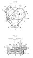
- Fig. 1 is a plan view of a movable magnet type instrument in accordance with a first embodiment mode of the present invention.
- Fig. 2 is a sectional view along an A-A line of Fig. 1.
- Fig. 3 is a plan view showing a transmitting means.
- Fig. 4 is a block diagram showing a control means.
- Fig. 5 is a waveform diagram of a driving signal supplied to a coil.
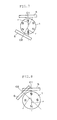
- Fig. 6 is an explanatory view showing the relation of a magnetic pole number and an acute angle formed by a winding central axis of the coil in this embodiment mode.
- Fig. 7 is an explanatory view showing the relation of the magnetic pole number and the acute angle formed by the winding central axis of the coil in a modified example of this embodiment mode.
- Fig. 8 is an explanatory view showing the relation of the magnetic pole number and the acute angle formed by the winding central axis of the coil in a modified example of this embodiment mode.
- Fig. 9 is a sectional view of a movable magnet type instrument in accordance with a second embodiment mode of the present invention.
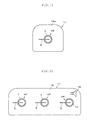
- Fig. 10 is a front view of the instrument device of a third embodiment mode.
- Fig. 11 is a front view of the instrument device of a fourth embodiment mode.
- Fig. 12 is a front view of the instrument device of a fifth embodiment mode.
- Fig. 13 is a front view of the instrument device of a sixth embodiment mode.
- a movable magnet type instrument M1 in a first embodiment mode of the present invention has a rotor magnet 1, a first shaft 2 for supporting this rotor magnet 1, a second shaft 3 spaced from this first shaft 2 at a predetermined interval and arranged in a parallel state, a housing 4, a pair of coils 5, 6, a protecting case 7, plural terminals 8, a pointer 9 and a transmitting means TR.
- the housing 4 supports these first and second shafts 2, 3 by bearings, and stores the rotor magnet 1 and a transmitting mechanism described later.
- the pair of coils 5, 6 is wound around the outside of this housing 4.
- the protecting case 7 includes one portion of these coils 5, 6 and covers the outer circumference of a predetermined necessary portion of the housing 4.
- Respective end portions of the coils 5, 6 are conducted and connected to the plural terminals 8.
- the pointer 9 is mounted to the tip of the second shaft 3 projected from the housing 4.
- the transmitting means TR is interposed between the rotor magnet 1 and the pointer 9, and transmits rotation of the rotor magnet 1 to the pointer 9.
- the rotor magnet 1 is constructed by a plastic magnet of a disk shape in which four magnetic poles in total are magnetized in the radial direction in a mutually equal area ratio of each 1/4 such that the magnetic poles adjacent to each other are set to different poles in N and S poles (see Fig. 3).
- the rotor magnet 1 is supported by the housing 4 through the first shaft 2 such that the rotor magnet 1 is integrally rotated (associated) with the first shaft 2.
- the transmitting means TR is constructed by a first gear TR1 fixed to the first shaft 2 and associated with the rotor magnet 1, and a second gear TR2 connected and engaged with this first gear TR1 and fixed to the second shaft 3 and associated with the second shaft 3.
- the first gear TR1 is formed such that the first gear TR1 has a diameter smaller than that of the second gear TR2.
- "14" continuous teeth are formed in the outer circumference of this first gear TR1.
- the second gear TR2 is formed such that this second gear TR2 has a diameter greater than that of the first gear TR1.
- "56" continuous teeth are formed in the outer circumference of the second gear TR2.
- the housing 4 is formed by synthetic resin, and is divided into a first frame body 41 located on the lower side and a second frame body 42 located on the upper side in Fig. 2.
- a cavity portion S is formed between the first frame body 41 and the second frame body 42.
- the rotor magnet 1 and the transmitting means TR are stored into this cavity portion S, and the first and second shafts 2, 3 are pivoted.
- One end of the second shaft 3 is projected to the exterior from the housing 4, and the pointer 9 is mounted to the tip of the projected end.
- the coils 5, 6 are located in the radial direction outer circumference of the rotor magnet 1 in which no second gear TR2 is arranged.
- a winding diameter corresponding to the radial circumference face of the rotor magnet 1 is set such that the winding diameter is gradually increased toward the first shaft 2.
- winding central axes C1, C2 of the respective coils 5, 6 extend to the first axis 2 side, and cross each other at the rotation center RC of the rotor magnet 1 (intersection point).
- An acute angle r formed by crossing the respective winding central axes C1, C2 at this time is set to about 45 degrees in this embodiment.
- the directions of the winding central axes C1, C2 of the respective coils 5, 6 are a magnetic field generating direction in which a magnetic field is generated from the coils 5, 6.
- the acute angle r of 45 degrees is an intermediate angle of 90 degrees formed in the coil 5 by an N-pole on the opposite side and one of S-poles adjacent to this N-pole on the opposite side in e.g., the opposite state of the N-poles in the case of the rotor magnet 1 of four poles in this embodiment mode as shown in Fig. 6.
- the acute angle r in the case of the rotor magnet 1 of six poles is 30 degrees as an intermediate angle of 60 degrees formed in the coil 5 by an S-pole located by 180 degrees on the opposite side and one of N-poles adjacent to this S-pole on the opposite side in the opposite state of the N-poles.
- the acute angle r of 45 degrees formed by crossing the winding central axes C1, C2 may be also formed by arranging the coils 5, 6 as shown in Fig. 8.
- the protecting case 7 of a cup shape is mounted to the housing 4 winding the coils 5, 6 therearound.
- a predetermined required area of the housing 4 except for an area corresponding to the second gear TR2, i.e., only an area of the housing 4 not including the corresponding area of the second gear TR2 and located on the side opposed to the pointer 9 side is covered with the protecting case 7.
- the protecting case 7 is formed by aluminum, etc. as a nonmagnetic material and is arranged to protect the coils 5, 6. Thus, cost can be restrained since the protecting case 7 is formed without using an expensive magnetic material.
- the material of the protecting cover 7 is not limited to aluminum, but may be also formed by synthetic resin.
- the movable magnet type instrument M1 constructed in this way is operated by a control means 120 including a control section 100 and a driving processing section 110.
- the control section 100 is constructed by a microcomputer.
- the control section 100 includes a CPU for executing a control program, a ROM for storing the control program, a RAM for temporarily storing arithmetically processed data, an interface (I/F) for inputting a signal from the exterior, and a bus for connecting each of the CPU, the ROM, the RAM and the interface.
- the control section 100 is arranged on the vehicle body side. In this case, a sensor 130 for detecting rotation of the output shaft of a transmission and outputting a predetermined pulse signal is connected to the control section 100.
- the control section 100 When the pulse signal (an input signal based on a measured amount) from this sensor 130 is inputted to the control section 100, the control section 100 arithmetically calculates this pulse signal, and converts this pulse signal to the indicating position of an unillustrated character plate described later. The control section 100 performs processing for calculating indication angle data on this character plate of the pointer 9, and outputs these indication angle data to the driving processing section 110 at the subsequent stage.
- the driving processing section 110 includes a ROM section for storing current flowing amount data of the respective coils 5, 6 according to the above indication angle data, a D/A converting section for converting an output value of each ROM section to an analog amount, and a driving output section for supplying a driving voltage corresponding to this analog amount to each of the coils 5, 6.
- the above indication angle data from the control section 100 are converted by this driving processing section 110 to a driving signal having a different electrical angle (phase angle), more particularly, a voltage signal of sine and cosine waveforms having different phases at the electrical angle as shown in Fig. 5, or the voltage signal of a waveform close to these waveforms.
- the converted signal is supplied to each of the coils 5, 6.
- a synthetic magnetic field vector according to the measured amount is formed by each of the coils 5, 6, and the rotor magnet 1 is rotated by an angle according to the measured amount in accordance with this synthetic magnetic field vector.
- the pointer 9 is also correspondingly rotated and the measured amount is indicated on the above character plate.
- the number of first gears TR1 is set to "14", and the number of second gears TR2 is set to "56".
- the gear ratio of the respective gears TR1, TR2 is set to 1/4.
- the transmitting means TR functions as a speed reduction transmitting means so that the pointer 9 is decelerated to 1/4 in rotation with respect to the rotor magnet 1. Therefore, the rotor magnet 1 requires a rotation angle four times the angle (rotation angle) of deviation of the pointer 9 to rotate the pointer 9 by a predetermined deviation angle. For example, when an input signal from the sensor 130 corresponds to the deviation angle of 90 degrees in the pointer 9, it is necessary to rotate the rotor magnet 1 at a mechanical angle of 360 degrees. Accordingly, the control means 120 repeatedly supplies twice the driving signal corresponding to the electrical angle of 2 ⁇ (one period) to each of the coils 5, 6 as the driving signal for rotating the rotor magnet 1 by the mechanical angle of 360 degrees.
- the rotation angle of the rotor magnet 1 obtained by the supply of the driving signal (hereinafter called the signal supply of 2 ⁇ ) corresponding to the electrical angle of 2 ⁇ is the mechanical angle of 180 degrees.
- the deviation angle (rotation angle) of the pointer 9 deviated through the transmitting means TR is similarly the mechanical angle of 45 degrees.
- the signal supply of 2 ⁇ is continuously repeated to obtain the deviation angle of the pointer 9 such as 90 degrees, 135 degrees and 180 degrees greater than 45 degrees.
- the influence of the rotor magnet 1 exerted by earth magnetism, etc. can be reduced and the rotor magnet 1 can be operated by the above construction in comparison with the case of two-pole magnetization. Accordingly, the rotor magnet 1 can be operated without covering the rotor magnet 1 with a magnetic material. Therefore, it is sufficient to form the protecting cover 7 by a cheap material instead of the magnetic material to only protect the coils 5, 6 from physical damage, etc. Accordingly, cost can be reduced in comparison with the conventional movable magnet type instrument.
- the driving signal having a different electrical angle is supplied to the pair of coils 5, 6 and the rotor magnet 1 is rotated and operated, it is sufficient to set a magnetic pole number n of the rotor magnet 1 to 4 or more (a natural number (N) multiple of 2 equal to or greater than 4).
- N natural number
- the acute angle r formed by crossing the directions of magnetic fields respectively generated by supplying the driving signal to the pair of coils 5, 6 is about 45 degrees as in this embodiment mode as shown in Fig. 6 in the case of a magnetic pole number "4", and is 30 degrees as shown in Fig. 7 in the case of a magnetic pole number "6".
- the transmitting means TR is constructed by two gears TR1, TR2, but the number of gears constituting the transmitting means TR is arbitrary.
- the transmitting means TR may be constructed by a first gear TR11, a second gear TR12, a third gear TR13 and a fourth gear TR14 as in a movable magnet type instrument M2 shown in Fig. 9 as a second embodiment mode of the present invention.
- the first gear TR11 is held by the first shaft 2 together with the rotor magnet 1 so as to be independently rotated, and is rotated in association with the rotor magnet 1.
- the second gear TR12 is fixed to the second shaft 3, and is rotated together with the second shaft 3.
- the third gear TR13 is fixed to the second shaft 3 together with this second gear TR12, and is rotated together with the second gear TR12.
- the fourth gear TR14 is fixed to the first shaft 2 and is rotated together with the first shaft 2.
- the rotation of the first gear TR11 associated with the rotor magnet 1 is transmitted to the second gear TR12, and the rotation of the second gear TR12 is transmitted to the fourth gear TR14 through the third gear TR13 so that the pointer 9 mounted to the first shaft 2 is operated.
- the decelerated and rotated transmitting means TR since the decelerated and rotated transmitting means TR is arranged, it is possible to provide the movable magnet type instrument M2 in which the influence of the rotor magnet 1 exerted by earth magnetism is further restrained, and indication with high accuracy can be performed.
- the pointer 9 may be also directly arranged in the first shaft 2 without arranging the transmitting means TR described in each of the above embodiment modes.
- the protecting case 7 is arranged. However, when it is not necessary to protect the coils 5, 6, etc., it is not necessary to arrange the protecting case 7. In accordance with such a construction, the number of parts can be reduced. Further cost can be also reduced.
- An instrument device 11 of this embodiment mode is usually used in a vehicle such as an automobile, etc., and is called a so-called combination meter, and indicates and displays plural measuring items by one movable magnet type instrument.
- This instrument device 11 has plural movable magnet type instruments m1 to m4. These movable magnet type instruments m1 to m4 are mounted to a hard circuit substrate 12 constructed by glass epoxy resin, etc.
- Movable magnet type instruments m3, m4 are adjacently arranged. One group of these movable magnet type instruments m3, m4, the movable magnet type instrument m1 and the movable magnet type instrument m2 are arranged in a state in which these movable magnet type instruments are separated from each other. The movable magnet type instruments m1, m2 are separated from each other to such an extent that there is no fear that magnetic interference is mutually caused.
- Fig. 10 simplifies and illustrates the movable magnet type instruments m1, m2, m3 and m4.
- the movable magnet type instruments m1, m2 have the same construction as the above movable magnet type instrument M1, and have the protecting case 7 formed from a nonmagnetic material such as aluminum.
- the movable magnet type instruments m3, m4 have the same construction as the fundamental construction of the movable magnet type instrument M1, but differ from the movable magnet type instrument M1 in that a protecting case 13 formed from a magnetic material such as permalloy described later is arranged instead of the protecting case 7 formed from a nonmagnetic material.
- the movable magnet type instrument m1 is that of an engine tachometer for indicating and displaying an engine rotation number.
- the movable magnet type instrument m2 is that of a speedometer for indicating and displaying the speed of a vehicle.
- the movable magnet type instrument m3 is that of an engine water temperature gauge for indicating and displaying the temperature of cooling water of the engine.
- the movable magnet type instrument m4 is that of a fuel gauge for indicating and displaying the remaining amount of a fuel such as gasoline, etc. of the vehicle.
- a character plate, etc. having a scale and an index portion attached to the scale are normally arranged behind the pointer 9.
- the character plate, etc. are not required in the explanation of this embodiment mode. Accordingly, the character plate and other constructional members are not shown in the drawings.
- the influence of the rotor magnet 1 exerted by earth magnetism, etc. is small in comparison with the case of two-pole magnetization in the rotor magnet 1. Therefore, the rotor magnet 1 can be operated without using the expensive protecting case 13 constructed by the magnetic material even when no rotor magnet 1 is covered with the protecting case 13. Accordingly, for example, it is sufficient to arrange the protecting case 7 by a cheap material instead of the magnetic material so as to only protect the coils 5, 6 from physical damage, etc. Therefore, cost can be reduced in comparison with the conventional movable magnet type instrument main body.
- the movable magnet type instrument m3 used in this embodiment mode will next be explained.
- the movable magnet type instrument m4 has a structure similar to that of the movable magnet type instrument m3. Therefore, an explanation with respect to the movable magnet type instrument m4 is omitted.
- the movable magnet type instruments m3 and m4 are arranged in positions close to each other so that the movable magnet type instruments m3 and m4 are influenced by mutual magnetic fields of the rotor magnet 1. Therefore, the protecting case 13 is formed by a magnetic material.
- Manufacture cost of the instrument device 11 can be reduced as described above by using the movable magnet type instruments m1, m2 requiring no protecting case 13 constructed by an expensive magnetic material in the instrument device 11 of this embodiment mode.
- the manufacture cost can be particularly further reduced in the instrument device 11 using many movable magnet type instruments.
- the instrument device 11 has one movable magnet type instrument m2 constituting the speedometer of the above embodiment modes in a circuit substrate 12a comparatively compact in comparison with the circuit substrate 12 of the above third embodiment mode.
- Such an instrument device 11 indicates and displays only the speed of a vehicle, and is applied as a comparatively cheap instrument device 11.
- no movable magnet type instrument m2 has the expensive protecting case 13 constructed by a magnetic material. Therefore, manufacture cost can be reduced by adopting the present invention in comparison with the use of the conventional instrument device 11.
- a fifth embodiment mode will next be explained on the basis of Fig. 12. Portions equal to or corresponding to those in each of the above embodiment modes are designated by the same reference numerals, and their detailed explanations are omitted.
- the instrument device 11 has the same movable magnet type instruments m1, m2, m4 as the above third embodiment mode in the circuit substrate 12.
- parts such as a speaker 14 using the magnetic material are mounted to the circuit substrate 12.
- the movable magnet type instrument m4 having the protecting case 13 constructed by the magnetic material is used.
- the remaining amount of a fuel is indicated and displayed by only a fuel gauge for indicating and displaying the remaining amount
- engine water temperature is displayed by using an unillustrated light source, e.g., a light emitting diode, etc. Accordingly, an engine water temperature gauge is constructed by only the movable magnet type instrument m4.
- manufacture cost of the instrument device 1 can be reduced by using the movable magnet type instruments m1, m2 having the protecting case 7 constructed by a nonmagnetic material.
- manufacture cost can be particularly further reduced in the instrument device 11 using many movable magnet type instruments.
- the instrument device 11 of this embodiment mode has plural movable magnet type instruments m5 to m7.
- the movable magnet type instruments m5 to m7 differ from the movable magnet type instruments m1 to m4 of the above third to fifth embodiment modes in that the movable magnet type instruments m5 to m7 have no protecting cases 7, 16 themselves.
- the movable magnet type instrument m5 to m7 are mounted to the hard circuit substrate 12.
- the movable magnet type instrument m5 is that of an engine tachometer for indicating and displaying an engine rotation number.
- the movable magnet type instrument m6 is that of a speedometer for indicating and displaying the speed of a vehicle.
- the movable magnet type instrument m7 is that of a fuel gauge for indicating and displaying the remaining amount of a fuel such as gasoline of the vehicle, etc.
- the present invention can provide a movable magnet type instrument able to reduce cost so that the present invention can be utilized to reduce the cost of an instrument device using the movable magnet type instrument.
Landscapes
- Physics & Mathematics (AREA)
- General Physics & Mathematics (AREA)
- Engineering & Computer Science (AREA)
- Power Engineering (AREA)
- Instrument Panels (AREA)
- Measurement Of Length, Angles, Or The Like Using Electric Or Magnetic Means (AREA)
Abstract
The invention provides a movable magnet type
instrument able to reduce cost and an instrument device
using this movable magnet type instrument. The movable
magnet type instrument M1 has a rotor magnet 1 magnetized
such that adjacent magnetic poles are poles different from
each other; a pair of coils 5, 6 arranged around this
rotor magnet 1 and having winding central axes C1, C2
crossing each other without being perpendicular to each
other; control means 120 for processing an input signal
based on a measured amount and supplying a driving signal
mutually having a different electrical angle to each of
the coils 5, 6 and rotating and operating the rotor
magnet; and a pointer 9 for rotating the rotor magnet 1 as
a driving source; wherein, when the number of magnetic
poles of the rotor magnet 1 is set to n and an acute angle
formed by crossing the winding central axes C1, C2 is set
to r, the acute angle r is set to an angle calculated by
360/2n (n is a multiple of 2 equal to or greater than 4).
Description
The present invention relates to a movable magnet
type instrument for operating a pointer and an instrument
device using this movable magnet type instrument.
For example, the movable magnet type instrument of a
crossing coil type is generally known as an instrument
main body applied to an instrument device for a vehicle.
Such a movable magnet type instrument is also called as an
air core movement, and a rotor magnet magnetized by two
poles of N and S poles is stored into a space formed in a
housing. A rotor shaft fixed to the rotor magnet is
pivoted by the housing. Further, one end of the rotor
shaft is projected to the exterior of the housing, and the
pointer is mounted. A pair of coils is orthogonally wound
around the outer circumference of the housing. Driving
signals having electrical angles different from each other,
concretely, voltage signals of sine and cosine waves
having different phases at the electrical angles are
supplied to each coil. The rotor magnet is pivotally
rotated by a synthetic magnetic field generated by each
coil by this supply of the driving signal. The pointer
can be angularly moved in accordance with a measuring
amount by controlling the supply of the driving signal to
each coil in accordance with a measured amount such as a
vehicle speed, an engine rotation.
In such a movable magnet type instrument, a main
portion of the movable magnet type instrument is covered
with a shield case constructed by a magnetic material such
as an iron nickel alloy such that no rotor magnet
magnetized by the two poles is influenced by earth
magnetism.
In the above movable magnet type instrument, the
shield case constructed by the magnetic material such as
the iron nickel alloy is required in consideration of
magnetic interference with the rotor magnet, etc.,
magnetic efficiency, etc. Therefore, the number of parts
cannot be reduced and it is difficult to reduce cost since
the magnetic material such as the iron nickel alloy
forming the shield case is expensive.
Further, in the instrument device called a
combination meter, plural movable magnet type instruments
mentioned above are particularly arranged. Therefore, the
cost of the above movable magnet type instrument is
further added to the cost of the instrument device as it
is, so that the cost of the instrument device is increased.
In view of this point, a main object of the present
invention is to provide a movable magnet type instrument
able to reduce cost and an instrument device using this
movable magnet type instrument.
The present invention resides in a movable magnet
type instrument comprising a rotor magnet magnetized such
that adjacent magnetic poles are poles different from each
other; a pair of coils arranged around this rotor magnet
and having winding central axes crossing each other
without being perpendicular to each other; control means
for processing an input signal based on a measured amount
and supplying a driving signal mutually having a different
electrical angle to each of said coils and rotating and
operating said rotor magnet; and a pointer for rotating
said rotor magnet as a driving source; wherein, when the
number of magnetic poles of said rotor magnet is set to n
and an acute angle formed by crossing said winding central
axes is set to r, the acute angle r is set to an angle
calculated by 360/2n (n is a multiple of 2 equal to or
greater than 4).
Further, a protecting cover for protecting said
coils and constructed by a nonmagnetic material is
arranged.
Further, transmitting means for transmitting
rotation of said rotor magnet to said pointer is arranged
between said pointer and said rotor magnet, and said
pointer is decelerated and rotated through said
transmitting means in comparison with said rotor magnet.
The present invention also resides in an instrument
device using at least one movable magnet type instrument
and comprising a rotor magnet magnetized by at least four
magnetic poles or more, a pair of coils arranged around
this rotor magnet and having winding central axes crossing
each other without being perpendicular to each other, and
a pointer rotated with said rotor magnet as a driving
source; wherein the instrument device has at least one
movable magnet type instrument in which, when the number
of magnetic poles of said rotor magnet is set to n and an
acute angle formed by crossing said winding central axes
is set to r, the acute angle r is set to an angle
calculated by 360/2n (n is a multiple of 2 equal to or
greater than 4).
Further, a protecting case for protecting said coils
and constructed by a nonmagnetic material is arranged in
said at least one movable magnet type instrument.
Further, transmitting means for transmitting
rotation of said rotor magnet to said pointer and
decelerating and rotating said pointer in comparison with
said rotor magnet is arranged between said pointer and
said rotor magnet in said at least one movable magnet type
instrument.
Fig. 1 is a plan view of a movable magnet type
instrument in accordance with a first embodiment mode of
the present invention. Fig. 2 is a sectional view along
an A-A line of Fig. 1. Fig. 3 is a plan view showing a
transmitting means. Fig. 4 is a block diagram showing a
control means. Fig. 5 is a waveform diagram of a driving
signal supplied to a coil. Fig. 6 is an explanatory view
showing the relation of a magnetic pole number and an
acute angle formed by a winding central axis of the coil
in this embodiment mode. Fig. 7 is an explanatory view
showing the relation of the magnetic pole number and the
acute angle formed by the winding central axis of the coil
in a modified example of this embodiment mode. Fig. 8 is
an explanatory view showing the relation of the magnetic
pole number and the acute angle formed by the winding
central axis of the coil in a modified example of this
embodiment mode. Fig. 9 is a sectional view of a movable
magnet type instrument in accordance with a second
embodiment mode of the present invention. Fig. 10 is a
front view of the instrument device of a third embodiment
mode. Fig. 11 is a front view of the instrument device of
a fourth embodiment mode. Fig. 12 is a front view of the
instrument device of a fifth embodiment mode. Fig. 13 is
a front view of the instrument device of a sixth
embodiment mode.
The embodiment modes of a movable magnet type
instrument in the present invention will next be explained
on the basis of the accompanying drawings.
A movable magnet type instrument M1 in a first
embodiment mode of the present invention has a rotor
magnet 1, a first shaft 2 for supporting this rotor magnet
1, a second shaft 3 spaced from this first shaft 2 at a
predetermined interval and arranged in a parallel state, a
housing 4, a pair of coils 5, 6, a protecting case 7,
plural terminals 8, a pointer 9 and a transmitting means
TR. The housing 4 supports these first and second shafts
2, 3 by bearings, and stores the rotor magnet 1 and a
transmitting mechanism described later. The pair of coils
5, 6 is wound around the outside of this housing 4. The
protecting case 7 includes one portion of these coils 5, 6
and covers the outer circumference of a predetermined
necessary portion of the housing 4. Respective end
portions of the coils 5, 6 are conducted and connected to
the plural terminals 8. The pointer 9 is mounted to the
tip of the second shaft 3 projected from the housing 4.
The transmitting means TR is interposed between the rotor
magnet 1 and the pointer 9, and transmits rotation of the
rotor magnet 1 to the pointer 9.
The rotor magnet 1 is constructed by a plastic
magnet of a disk shape in which four magnetic poles in
total are magnetized in the radial direction in a mutually
equal area ratio of each 1/4 such that the magnetic poles
adjacent to each other are set to different poles in N and
S poles (see Fig. 3). The rotor magnet 1 is supported by
the housing 4 through the first shaft 2 such that the
rotor magnet 1 is integrally rotated (associated) with the
first shaft 2.
The transmitting means TR is constructed by a first
gear TR1 fixed to the first shaft 2 and associated with
the rotor magnet 1, and a second gear TR2 connected and
engaged with this first gear TR1 and fixed to the second
shaft 3 and associated with the second shaft 3. In this
embodiment mode, the first gear TR1 is formed such that
the first gear TR1 has a diameter smaller than that of the
second gear TR2. "14" continuous teeth are formed in the
outer circumference of this first gear TR1. The second
gear TR2 is formed such that this second gear TR2 has a
diameter greater than that of the first gear TR1. "56"
continuous teeth are formed in the outer circumference of
the second gear TR2.
The housing 4 is formed by synthetic resin, and is
divided into a first frame body 41 located on the lower
side and a second frame body 42 located on the upper side
in Fig. 2. A cavity portion S is formed between the first
frame body 41 and the second frame body 42. The rotor
magnet 1 and the transmitting means TR are stored into
this cavity portion S, and the first and second shafts 2,
3 are pivoted. One end of the second shaft 3 is projected
to the exterior from the housing 4, and the pointer 9 is
mounted to the tip of the projected end.
The coils 5, 6 are located in the radial direction
outer circumference of the rotor magnet 1 in which no
second gear TR2 is arranged. A winding diameter
corresponding to the radial circumference face of the
rotor magnet 1 is set such that the winding diameter is
gradually increased toward the first shaft 2. In this
case, winding central axes C1, C2 of the respective coils
5, 6 extend to the first axis 2 side, and cross each other
at the rotation center RC of the rotor magnet 1
(intersection point). An acute angle r formed by crossing
the respective winding central axes C1, C2 at this time is
set to about 45 degrees in this embodiment. The
directions of the winding central axes C1, C2 of the
respective coils 5, 6 are a magnetic field generating
direction in which a magnetic field is generated from the
coils 5, 6. The acute angle r of 45 degrees is an
intermediate angle of 90 degrees formed in the coil 5 by
an N-pole on the opposite side and one of S-poles adjacent
to this N-pole on the opposite side in e.g., the opposite
state of the N-poles in the case of the rotor magnet 1 of
four poles in this embodiment mode as shown in Fig. 6.
For example, as shown in Fig. 7, the acute angle r
in the case of the rotor magnet 1 of six poles is 30
degrees as an intermediate angle of 60 degrees formed in
the coil 5 by an S-pole located by 180 degrees on the
opposite side and one of N-poles adjacent to this S-pole
on the opposite side in the opposite state of the N-poles.
The acute angle r of 45 degrees formed by crossing
the winding central axes C1, C2 may be also formed by
arranging the coils 5, 6 as shown in Fig. 8.
The protecting case 7 of a cup shape is mounted to
the housing 4 winding the coils 5, 6 therearound. In this
embodiment mode, a predetermined required area of the
housing 4 except for an area corresponding to the second
gear TR2, i.e., only an area of the housing 4 not
including the corresponding area of the second gear TR2
and located on the side opposed to the pointer 9 side is
covered with the protecting case 7. The protecting case 7
is formed by aluminum, etc. as a nonmagnetic material and
is arranged to protect the coils 5, 6. Thus, cost can be
restrained since the protecting case 7 is formed without
using an expensive magnetic material. The material of the
protecting cover 7 is not limited to aluminum, but may be
also formed by synthetic resin.
As shown in Fig. 4, the movable magnet type
instrument M1 constructed in this way is operated by a
control means 120 including a control section 100 and a
driving processing section 110.
The control section 100 is constructed by a
microcomputer. The control section 100 includes a CPU for
executing a control program, a ROM for storing the control
program, a RAM for temporarily storing arithmetically
processed data, an interface (I/F) for inputting a signal
from the exterior, and a bus for connecting each of the
CPU, the ROM, the RAM and the interface. The control
section 100 is arranged on the vehicle body side. In this
case, a sensor 130 for detecting rotation of the output
shaft of a transmission and outputting a predetermined
pulse signal is connected to the control section 100.
When the pulse signal (an input signal based on a
measured amount) from this sensor 130 is inputted to the
control section 100, the control section 100
arithmetically calculates this pulse signal, and converts
this pulse signal to the indicating position of an
unillustrated character plate described later. The
control section 100 performs processing for calculating
indication angle data on this character plate of the
pointer 9, and outputs these indication angle data to the
driving processing section 110 at the subsequent stage.
The driving processing section 110 includes a ROM
section for storing current flowing amount data of the
respective coils 5, 6 according to the above indication
angle data, a D/A converting section for converting an
output value of each ROM section to an analog amount, and
a driving output section for supplying a driving voltage
corresponding to this analog amount to each of the coils 5,
6. The above indication angle data from the control
section 100 are converted by this driving processing
section 110 to a driving signal having a different
electrical angle (phase angle), more particularly, a
voltage signal of sine and cosine waveforms having
different phases at the electrical angle as shown in Fig.
5, or the voltage signal of a waveform close to these
waveforms. The converted signal is supplied to each of
the coils 5, 6.
Thus, a synthetic magnetic field vector according to
the measured amount is formed by each of the coils 5, 6,
and the rotor magnet 1 is rotated by an angle according to
the measured amount in accordance with this synthetic
magnetic field vector. The pointer 9 is also
correspondingly rotated and the measured amount is
indicated on the above character plate.
In the case of this embodiment mode, the number of
first gears TR1 is set to "14", and the number of second
gears TR2 is set to "56". The gear ratio of the
respective gears TR1, TR2 is set to 1/4. Accordingly, the
transmitting means TR functions as a speed reduction
transmitting means so that the pointer 9 is decelerated to
1/4 in rotation with respect to the rotor magnet 1.
Therefore, the rotor magnet 1 requires a rotation angle
four times the angle (rotation angle) of deviation of the
pointer 9 to rotate the pointer 9 by a predetermined
deviation angle. For example, when an input signal from
the sensor 130 corresponds to the deviation angle of 90
degrees in the pointer 9, it is necessary to rotate the
rotor magnet 1 at a mechanical angle of 360 degrees.
Accordingly, the control means 120 repeatedly supplies
twice the driving signal corresponding to the electrical
angle of 2π (one period) to each of the coils 5, 6 as the
driving signal for rotating the rotor magnet 1 by the
mechanical angle of 360 degrees.
Accordingly, the rotation angle of the rotor magnet
1 obtained by the supply of the driving signal
(hereinafter called the signal supply of 2π)
corresponding to the electrical angle of 2π is the
mechanical angle of 180 degrees. The deviation angle
(rotation angle) of the pointer 9 deviated through the
transmitting means TR is similarly the mechanical angle of
45 degrees. The signal supply of 2π is continuously
repeated to obtain the deviation angle of the pointer 9
such as 90 degrees, 135 degrees and 180 degrees greater
than 45 degrees.
The influence of the rotor magnet 1 exerted by earth
magnetism, etc. can be reduced and the rotor magnet 1 can
be operated by the above construction in comparison with
the case of two-pole magnetization. Accordingly, the
rotor magnet 1 can be operated without covering the rotor
magnet 1 with a magnetic material. Therefore, it is
sufficient to form the protecting cover 7 by a cheap
material instead of the magnetic material to only protect
the coils 5, 6 from physical damage, etc. Accordingly,
cost can be reduced in comparison with the conventional
movable magnet type instrument.
Further, when the driving signal having a different
electrical angle is supplied to the pair of coils 5, 6 and
the rotor magnet 1 is rotated and operated, it is
sufficient to set a magnetic pole number n of the rotor
magnet 1 to 4 or more (a natural number (N) multiple of 2
equal to or greater than 4). In this case, it is
sufficient that the acute angle r formed by crossing the
directions of magnetic fields respectively generated by
supplying the driving signal to the pair of coils 5, 6 is
about 45 degrees as in this embodiment mode as shown in
Fig. 6 in the case of a magnetic pole number "4", and is
30 degrees as shown in Fig. 7 in the case of a magnetic
pole number "6". It is sufficient to set the acute angle
r to a half (1/2) of (360 degrees/magnetic pole number n).
When the magnetic pole number is "8" although this
magnetic pole number 8 is not illustrated in the drawings,
it is sufficient to set the acute angle r to 22.5 degrees
as a half (1/2) of (360 degrees/magnetic pole number n).
Further, in this embodiment mode, the transmitting
means TR is constructed by two gears TR1, TR2, but the
number of gears constituting the transmitting means TR is
arbitrary. For example, the transmitting means TR may be
constructed by a first gear TR11, a second gear TR12, a
third gear TR13 and a fourth gear TR14 as in a movable
magnet type instrument M2 shown in Fig. 9 as a second
embodiment mode of the present invention. The first gear
TR11 is held by the first shaft 2 together with the rotor
magnet 1 so as to be independently rotated, and is rotated
in association with the rotor magnet 1. The second gear
TR12 is fixed to the second shaft 3, and is rotated
together with the second shaft 3. The third gear TR13 is
fixed to the second shaft 3 together with this second gear
TR12, and is rotated together with the second gear TR12.
The fourth gear TR14 is fixed to the first shaft 2 and is
rotated together with the first shaft 2. The rotation of
the first gear TR11 associated with the rotor magnet 1 is
transmitted to the second gear TR12, and the rotation of
the second gear TR12 is transmitted to the fourth gear
TR14 through the third gear TR13 so that the pointer 9
mounted to the first shaft 2 is operated.
Thus, since the decelerated and rotated transmitting
means TR is arranged, it is possible to provide the
movable magnet type instrument M2 in which the influence
of the rotor magnet 1 exerted by earth magnetism is
further restrained, and indication with high accuracy can
be performed.
Further, the pointer 9 may be also directly arranged
in the first shaft 2 without arranging the transmitting
means TR described in each of the above embodiment modes.
In each of the above embodiment modes, the
protecting case 7 is arranged. However, when it is not
necessary to protect the coils 5, 6, etc., it is not
necessary to arrange the protecting case 7. In accordance
with such a construction, the number of parts can be
reduced. Further cost can be also reduced.
A third embodiment mode of the present invention
will next be explained. The same reference numerals are
designated in portions equal to or corresponding to those
in the above embodiment modes, and their detailed
explanations are omitted.
An instrument device 11 of this embodiment mode is
usually used in a vehicle such as an automobile, etc., and
is called a so-called combination meter, and indicates and
displays plural measuring items by one movable magnet type
instrument. This instrument device 11 has plural movable
magnet type instruments m1 to m4. These movable magnet
type instruments m1 to m4 are mounted to a hard circuit
substrate 12 constructed by glass epoxy resin, etc.
Movable magnet type instruments m3, m4 are
adjacently arranged. One group of these movable magnet
type instruments m3, m4, the movable magnet type
instrument m1 and the movable magnet type instrument m2
are arranged in a state in which these movable magnet type
instruments are separated from each other. The movable
magnet type instruments m1, m2 are separated from each
other to such an extent that there is no fear that
magnetic interference is mutually caused.
Fig. 10 simplifies and illustrates the movable
magnet type instruments m1, m2, m3 and m4. The movable
magnet type instruments m1, m2 have the same construction
as the above movable magnet type instrument M1, and have
the protecting case 7 formed from a nonmagnetic material
such as aluminum. The movable magnet type instruments m3,
m4 have the same construction as the fundamental
construction of the movable magnet type instrument M1, but
differ from the movable magnet type instrument M1 in that
a protecting case 13 formed from a magnetic material such
as permalloy described later is arranged instead of the
protecting case 7 formed from a nonmagnetic material.
The movable magnet type instrument m1 is that of an
engine tachometer for indicating and displaying an engine
rotation number. The movable magnet type instrument m2 is
that of a speedometer for indicating and displaying the
speed of a vehicle. The movable magnet type instrument m3
is that of an engine water temperature gauge for
indicating and displaying the temperature of cooling water
of the engine. The movable magnet type instrument m4 is
that of a fuel gauge for indicating and displaying the
remaining amount of a fuel such as gasoline, etc. of the
vehicle.
A character plate, etc. having a scale and an index
portion attached to the scale are normally arranged behind
the pointer 9. However, the character plate, etc. are not
required in the explanation of this embodiment mode.
Accordingly, the character plate and other constructional
members are not shown in the drawings.
In the movable magnet type instruments m1, m2, the
influence of the rotor magnet 1 exerted by earth magnetism,
etc. is small in comparison with the case of two-pole
magnetization in the rotor magnet 1. Therefore, the rotor
magnet 1 can be operated without using the expensive
protecting case 13 constructed by the magnetic material
even when no rotor magnet 1 is covered with the protecting
case 13. Accordingly, for example, it is sufficient to
arrange the protecting case 7 by a cheap material instead
of the magnetic material so as to only protect the coils 5,
6 from physical damage, etc. Therefore, cost can be
reduced in comparison with the conventional movable magnet
type instrument main body.
The movable magnet type instrument m3 used in this
embodiment mode will next be explained. The movable
magnet type instrument m4 has a structure similar to that
of the movable magnet type instrument m3. Therefore, an
explanation with respect to the movable magnet type
instrument m4 is omitted.
The movable magnet type instruments m3 and m4 are
arranged in positions close to each other so that the
movable magnet type instruments m3 and m4 are influenced
by mutual magnetic fields of the rotor magnet 1.
Therefore, the protecting case 13 is formed by a magnetic
material.
Manufacture cost of the instrument device 11 can be
reduced as described above by using the movable magnet
type instruments m1, m2 requiring no protecting case 13
constructed by an expensive magnetic material in the
instrument device 11 of this embodiment mode. The
manufacture cost can be particularly further reduced in
the instrument device 11 using many movable magnet type
instruments.
A fourth embodiment mode will next be explained on
the basis of Fig. 11. Portions equal to or corresponding
to those in the above embodiment modes are designated by
the same reference numerals, and their detailed
explanations are omitted.
In this embodiment mode, the instrument device 11
has one movable magnet type instrument m2 constituting the
speedometer of the above embodiment modes in a circuit
substrate 12a comparatively compact in comparison with the
circuit substrate 12 of the above third embodiment mode.
Such an instrument device 11 indicates and displays only
the speed of a vehicle, and is applied as a comparatively
cheap instrument device 11. In such an instrument device
11, no movable magnet type instrument m2 has the expensive
protecting case 13 constructed by a magnetic material.
Therefore, manufacture cost can be reduced by adopting the
present invention in comparison with the use of the
conventional instrument device 11.
A fifth embodiment mode will next be explained on
the basis of Fig. 12. Portions equal to or corresponding
to those in each of the above embodiment modes are
designated by the same reference numerals, and their
detailed explanations are omitted.
In this embodiment mode, the instrument device 11
has the same movable magnet type instruments m1, m2, m4 as
the above third embodiment mode in the circuit substrate
12. In this instrument device 11, parts such as a speaker
14 using the magnetic material are mounted to the circuit
substrate 12. When the movable magnet type instrument m4
must be arranged in the vicinity of the parts, etc. using
such a magnetic material, the movable magnet type
instrument m4 having the protecting case 13 constructed by
the magnetic material is used. In this embodiment mode,
the remaining amount of a fuel is indicated and displayed
by only a fuel gauge for indicating and displaying the
remaining amount, and engine water temperature is
displayed by using an unillustrated light source, e.g., a
light emitting diode, etc. Accordingly, an engine water
temperature gauge is constructed by only the movable
magnet type instrument m4.
As mentioned above, when the movable magnet type
instrument m4 having the protecting case 13 constructed by
the magnetic material is used only in the vicinity of
parts, etc. using the magnetic material and is arranged in
a position separated from the parts using the magnetic
material, manufacture cost of the instrument device 1 can
be reduced by using the movable magnet type instruments m1,
m2 having the protecting case 7 constructed by a
nonmagnetic material. The manufacture cost can be
particularly further reduced in the instrument device 11
using many movable magnet type instruments.
A sixth embodiment mode will next be explained on
the basis of Fig. 13. Portions equal to or corresponding
to those in each of the above embodiment modes are
designated by the same reference numerals, and their
detailed explanations are omitted.
The instrument device 11 of this embodiment mode has
plural movable magnet type instruments m5 to m7. The
movable magnet type instruments m5 to m7 differ from the
movable magnet type instruments m1 to m4 of the above
third to fifth embodiment modes in that the movable magnet
type instruments m5 to m7 have no protecting cases 7, 16
themselves.
These movable magnet type instruments m5 to m7 are
mounted to the hard circuit substrate 12. The movable
magnet type instrument m5 is that of an engine tachometer
for indicating and displaying an engine rotation number.
The movable magnet type instrument m6 is that of a
speedometer for indicating and displaying the speed of a
vehicle. The movable magnet type instrument m7 is that of
a fuel gauge for indicating and displaying the remaining
amount of a fuel such as gasoline of the vehicle, etc.
It is not necessary to protect the coils 5, 6 of the
movable magnet type instruments m5 to m7 so that it is not
necessary to arrange the protecting cases 7, 16. In
accordance with such a construction, the number of parts
can be reduced so that cost can be further reduced.
The present invention can provide a movable magnet
type instrument able to reduce cost so that the present
invention can be utilized to reduce the cost of an
instrument device using the movable magnet type instrument.
Claims (6)
- A movable magnet type instrument comprising a rotor magnet magnetized such that adjacent magnetic poles are poles different from each other; a pair of coils arranged around this rotor magnet and having winding central axes crossing each other without being perpendicular to each other; control means for processing an input signal based on a measured amount and supplying a driving signal mutually having a different electrical angle to each of said coils and rotating and operating said rotor magnet; and a pointer for rotating said rotor magnet as a driving source; wherein, when the number of magnetic poles of said rotor magnet is set to n and an acute angle formed by crossing said winding central axes is set to r, the acute angle r is set to an angle calculated by 360/2n (n is a multiple of 2 equal to or greater than 4).
- A movable magnet type instrument according to claim 1, wherein a protecting cover for protecting said coils and constructed by a nonmagnetic material is arranged.
- A movable magnet type instrument according to claim 1 or 2, wherein transmitting means for transmitting rotation of said rotor magnet to said pointer is arranged between said pointer and said rotor magnet, and said pointer is decelerated and rotated through said transmitting means in comparison with said rotor magnet.
- An instrument device using at least one movable magnet type instrument and comprising a rotor magnet magnetized by at least four magnetic poles or more, a pair of coils arranged around this rotor magnet and having winding central axes crossing each other without being perpendicular to each other, and a pointer rotated with said rotor magnet as a driving source; wherein the instrument device has at least one movable magnet type instrument in which, when the number of magnetic poles of said rotor magnet is set to n and an acute angle formed by crossing said winding central axes is set to r, the acute angle r is set to an angle calculated by 360/2n (n is a multiple of 2 equal to or greater than 4).
- An instrument device using the movable magnet type instrument according to claim 4, wherein a protecting case for protecting said coils and constructed by a nonmagnetic material is arranged in said at least one movable magnet type instrument.
- An instrument device using the movable magnet type instrument according to any one of claim 4 or 5, wherein transmitting means for transmitting rotation of said rotor magnet to said pointer and decelerating and rotating said pointer in comparison with said rotor magnet is arranged between said pointer and said rotor magnet in said at least one movable magnet type instrument.
Applications Claiming Priority (5)
| Application Number | Priority Date | Filing Date | Title |
|---|---|---|---|
| JP2000337260A JP3371961B2 (en) | 2000-10-31 | 2000-10-31 | Moving magnet type instrument |
| JP2000337260 | 2000-10-31 | ||
| JP2000399788 | 2000-12-28 | ||
| JP2000399788A JP2002202160A (en) | 2000-12-28 | 2000-12-28 | Instrument device |
| PCT/JP2001/009170 WO2002037062A1 (en) | 2000-10-31 | 2001-10-18 | Movable-magnet type meter and meter device using this movable-magnet type meter |
Publications (2)
| Publication Number | Publication Date |
|---|---|
| EP1335191A1 true EP1335191A1 (en) | 2003-08-13 |
| EP1335191A4 EP1335191A4 (en) | 2004-12-15 |
Family
ID=26603429
Family Applications (1)
| Application Number | Title | Priority Date | Filing Date |
|---|---|---|---|
| EP01976754A Withdrawn EP1335191A4 (en) | 2000-10-31 | 2001-10-18 | MOBILE MAGNET TYPE COUNTER AND COUNTER DEVICE USING SAID MOBILE MAGNET TYPE COUNTER |
Country Status (5)
| Country | Link |
|---|---|
| US (1) | US6727622B2 (en) |
| EP (1) | EP1335191A4 (en) |
| KR (1) | KR20020067924A (en) |
| CN (1) | CN1229628C (en) |
| WO (1) | WO2002037062A1 (en) |
Cited By (1)
| Publication number | Priority date | Publication date | Assignee | Title |
|---|---|---|---|---|
| FR2882460A1 (en) * | 2005-02-24 | 2006-08-25 | Peugeot Citroen Automobiles Sa | Speed and operating parameter indicating device for motor vehicle, has coupling unit mounted with axle of motor and including base coupled with needle end and pin engaging in needle`s orifice, where needle and unit are integrated by magnets |
Families Citing this family (4)
| Publication number | Priority date | Publication date | Assignee | Title |
|---|---|---|---|---|
| US7171498B2 (en) * | 2003-01-09 | 2007-01-30 | Sony Computer Entertainment America Inc. | Alphanumeric keyboard input system using a game controller |
| JP4298311B2 (en) * | 2003-02-07 | 2009-07-15 | キヤノン株式会社 | motor |
| JP4458988B2 (en) * | 2004-08-31 | 2010-04-28 | 日本精機株式会社 | Magnet rotor, movable magnet type instrument having the magnet rotor, and stepping motor having the magnet rotor |
| KR102260144B1 (en) | 2021-01-04 | 2021-06-09 | 주식회사 유림테크 | Moving coil type insulation resistance and voltage meter device |
Family Cites Families (14)
| Publication number | Priority date | Publication date | Assignee | Title |
|---|---|---|---|---|
| NL7308770A (en) * | 1973-06-22 | 1974-12-24 | Speedometer-kilometer meter for vehicles - pulse generator drives stepping motor connected to kilometer counter and speed indicator | |
| JPS5387692A (en) | 1977-01-12 | 1978-08-02 | Nec Corp | Moving magnet type display device |
| US4782353A (en) * | 1984-02-27 | 1988-11-01 | Seikosha Co., Ltd. | Stepping motor-driven sector opening/closing device |
| JP2500242Y2 (en) * | 1990-02-21 | 1996-06-05 | 矢崎総業株式会社 | Cross coil type indicator |
| JPH06101922B2 (en) | 1990-07-30 | 1994-12-12 | いすゞ自動車株式会社 | Eddy current type speed reducer |
| FR2706039B1 (en) * | 1993-06-04 | 1995-08-04 | Sagem | Logometer. |
| US5578918A (en) * | 1994-07-21 | 1996-11-26 | Floscan Instrument Company, Inc. | Modular two or three coil movement having a magnet homing free cross sectional shape of the shield pot |
| JPH08251902A (en) | 1995-03-07 | 1996-09-27 | Canon Inc | Step motor |
| FR2742940B1 (en) * | 1995-12-22 | 1998-03-13 | Moving Magnet Tech | DIPHASE MOTOR, IN PARTICULAR A WATCHMAKING MOTOR OR A MOTOR FOR DRIVING A DISPLAY HAND |
| FR2747196B1 (en) * | 1996-04-05 | 1998-06-26 | Magneti Marelli France | MOTOR DEVICE WITH ELECTROMAGNETIC CONTROL, ESPECIALLY LOGOMETER |
| FR2754953B1 (en) * | 1996-10-21 | 1999-02-26 | Moving Magnet Tech | POLYPHASE MOTOR, PARTICULARLY FOR DRIVING A DISPLAY HAND |
| US6388346B1 (en) * | 1998-10-14 | 2002-05-14 | Air Concepts, Inc. | Axial fluid flow inducing device with multiple magnetically driven impellers |
| US6055857A (en) * | 1998-11-10 | 2000-05-02 | Chrysler Corporation | Instrument cluster gauge mounting means |
| JP3460812B2 (en) | 2000-01-31 | 2003-10-27 | 日本精機株式会社 | Moving magnet type instrument |
-
2001
- 2001-10-18 KR KR1020027008436A patent/KR20020067924A/en not_active Ceased
- 2001-10-18 WO PCT/JP2001/009170 patent/WO2002037062A1/en not_active Ceased
- 2001-10-18 EP EP01976754A patent/EP1335191A4/en not_active Withdrawn
- 2001-10-18 CN CNB018033253A patent/CN1229628C/en not_active Expired - Lifetime
- 2001-10-18 US US10/168,856 patent/US6727622B2/en not_active Expired - Lifetime
Cited By (1)
| Publication number | Priority date | Publication date | Assignee | Title |
|---|---|---|---|---|
| FR2882460A1 (en) * | 2005-02-24 | 2006-08-25 | Peugeot Citroen Automobiles Sa | Speed and operating parameter indicating device for motor vehicle, has coupling unit mounted with axle of motor and including base coupled with needle end and pin engaging in needle`s orifice, where needle and unit are integrated by magnets |
Also Published As
| Publication number | Publication date |
|---|---|
| CN1394274A (en) | 2003-01-29 |
| US6727622B2 (en) | 2004-04-27 |
| US20020190594A1 (en) | 2002-12-19 |
| EP1335191A4 (en) | 2004-12-15 |
| CN1229628C (en) | 2005-11-30 |
| KR20020067924A (en) | 2002-08-24 |
| WO2002037062A1 (en) | 2002-05-10 |
Similar Documents
| Publication | Publication Date | Title |
|---|---|---|
| JPS582756A (en) | Zero return type electric indicator | |
| KR101359881B1 (en) | Pointer measuring instrument | |
| KR100253600B1 (en) | Drive apparatus for stepping motor type meter | |
| KR20040022394A (en) | Meter unit having magnetic pointer position detector | |
| US4884058A (en) | Combination indicator apparatus for automotive vehicle | |
| US6727622B2 (en) | Movable-magnet type meter and meter device using this movable-magnet type meter | |
| KR970010004B1 (en) | Cross Coil Type Magnetic Magnetic Instrument | |
| US5063344A (en) | Mode selectable interface circuit for an air core gage controller | |
| JP2002202160A (en) | Instrument device | |
| KR20250093540A (en) | Multi-rotation angle detection device and segment counter therefor | |
| JP2002323350A (en) | Pointer display | |
| JP3371961B2 (en) | Moving magnet type instrument | |
| JP3460812B2 (en) | Moving magnet type instrument | |
| JP2009168598A (en) | Ultrasonic motor and pointer type display device | |
| JPH10267609A (en) | Rotational amount-measuring instrument | |
| CN209840955U (en) | Induction structure of intelligent corner transmitter | |
| JPH04258Y2 (en) | ||
| KR101400239B1 (en) | Indicator of marine apparatus using stepper motor comprising gears and method thereof | |
| JPH04102016U (en) | Vehicle display device | |
| GB2102955A (en) | Improvements relating to servo systems | |
| EP1493038B1 (en) | Cross-coil instrument with a predefined characteristic | |
| JPH06249881A (en) | Three-phase coil type revolution driving device | |
| JPH0725710Y2 (en) | Crossed coil instrument | |
| JPS6242380Y2 (en) | ||
| JP4695900B2 (en) | Instrument device |
Legal Events
| Date | Code | Title | Description |
|---|---|---|---|
| PUAI | Public reference made under article 153(3) epc to a published international application that has entered the european phase |
Free format text: ORIGINAL CODE: 0009012 |
|
| 17P | Request for examination filed |
Effective date: 20020702 |
|
| AK | Designated contracting states |
Designated state(s): DE FR GB IT |
|
| A4 | Supplementary search report drawn up and despatched |
Effective date: 20041103 |
|
| RIC1 | Information provided on ipc code assigned before grant |
Ipc: 7G 01D 13/22 A Ipc: 7H 02K 21/14 B Ipc: 7B 60K 35/00 B Ipc: 7G 01R 7/06 B |
|
| STAA | Information on the status of an ep patent application or granted ep patent |
Free format text: STATUS: THE APPLICATION HAS BEEN WITHDRAWN |
|
| 18W | Application withdrawn |
Effective date: 20061004 |