EP1335150A2 - Dynamic damper with multiple degree of freedom - Google Patents
Dynamic damper with multiple degree of freedom Download PDFInfo
- Publication number
- EP1335150A2 EP1335150A2 EP03250530A EP03250530A EP1335150A2 EP 1335150 A2 EP1335150 A2 EP 1335150A2 EP 03250530 A EP03250530 A EP 03250530A EP 03250530 A EP03250530 A EP 03250530A EP 1335150 A2 EP1335150 A2 EP 1335150A2
- Authority
- EP
- European Patent Office
- Prior art keywords
- mass
- tube member
- dynamic damper
- elastic members
- pair
- Prior art date
- Legal status (The legal status is an assumption and is not a legal conclusion. Google has not performed a legal analysis and makes no representation as to the accuracy of the status listed.)
- Granted
Links
Images


Classifications
-
- F—MECHANICAL ENGINEERING; LIGHTING; HEATING; WEAPONS; BLASTING
- F16—ENGINEERING ELEMENTS AND UNITS; GENERAL MEASURES FOR PRODUCING AND MAINTAINING EFFECTIVE FUNCTIONING OF MACHINES OR INSTALLATIONS; THERMAL INSULATION IN GENERAL
- F16F—SPRINGS; SHOCK-ABSORBERS; MEANS FOR DAMPING VIBRATION
- F16F15/00—Suppression of vibrations in systems; Means or arrangements for avoiding or reducing out-of-balance forces, e.g. due to motion
- F16F15/10—Suppression of vibrations in rotating systems by making use of members moving with the system
- F16F15/14—Suppression of vibrations in rotating systems by making use of members moving with the system using masses freely rotating with the system, i.e. uninvolved in transmitting driveline torque, e.g. rotative dynamic dampers
- F16F15/1407—Suppression of vibrations in rotating systems by making use of members moving with the system using masses freely rotating with the system, i.e. uninvolved in transmitting driveline torque, e.g. rotative dynamic dampers the rotation being limited with respect to the driving means
- F16F15/1414—Masses driven by elastic elements
-
- F—MECHANICAL ENGINEERING; LIGHTING; HEATING; WEAPONS; BLASTING
- F16—ENGINEERING ELEMENTS AND UNITS; GENERAL MEASURES FOR PRODUCING AND MAINTAINING EFFECTIVE FUNCTIONING OF MACHINES OR INSTALLATIONS; THERMAL INSULATION IN GENERAL
- F16F—SPRINGS; SHOCK-ABSORBERS; MEANS FOR DAMPING VIBRATION
- F16F15/00—Suppression of vibrations in systems; Means or arrangements for avoiding or reducing out-of-balance forces, e.g. due to motion
- F16F15/10—Suppression of vibrations in rotating systems by making use of members moving with the system
-
- F—MECHANICAL ENGINEERING; LIGHTING; HEATING; WEAPONS; BLASTING
- F16—ENGINEERING ELEMENTS AND UNITS; GENERAL MEASURES FOR PRODUCING AND MAINTAINING EFFECTIVE FUNCTIONING OF MACHINES OR INSTALLATIONS; THERMAL INSULATION IN GENERAL
- F16C—SHAFTS; FLEXIBLE SHAFTS; ELEMENTS OR CRANKSHAFT MECHANISMS; ROTARY BODIES OTHER THAN GEARING ELEMENTS; BEARINGS
- F16C2326/00—Articles relating to transporting
- F16C2326/01—Parts of vehicles in general
- F16C2326/06—Drive shafts
-
- F—MECHANICAL ENGINEERING; LIGHTING; HEATING; WEAPONS; BLASTING
- F16—ENGINEERING ELEMENTS AND UNITS; GENERAL MEASURES FOR PRODUCING AND MAINTAINING EFFECTIVE FUNCTIONING OF MACHINES OR INSTALLATIONS; THERMAL INSULATION IN GENERAL
- F16C—SHAFTS; FLEXIBLE SHAFTS; ELEMENTS OR CRANKSHAFT MECHANISMS; ROTARY BODIES OTHER THAN GEARING ELEMENTS; BEARINGS
- F16C3/00—Shafts; Axles; Cranks; Eccentrics
- F16C3/02—Shafts; Axles
- F16C3/023—Shafts; Axles made of several parts, e.g. by welding
Definitions
- the present invention relates to a dynamic damper to reduce bending vibrations, specifically, relates to the dynamic damper attached onto a torque transmission tube used for transmission of a driving force of a vehicle.
- Japanese Patent Application First Publication No. 2001-21002 published on January 26, 2001 exemplifies a previously proposed dynamic damper to be attached onto a torque transmission tube.
- the disclosed technique is the dynamic damper such that a mass member is disposed via an elastic member on an inner periphery of a torque transmission tube,and a weight center of the mass member and an elastic center of the elastic member are mutually deviated from each other in an axial center direction of the tube, so that bending and torsional vibrations of the torque transmission tube are effectively reduced.
- a specific value of a resonance of the bending vibration that can be reduced is, however, only one. Hence, a sufficient reduction of the bending vibration cannot be achieved by the previously proposed dynamic damper for specific values of resonances of the bending vibrations present in plural.
- an object of the present invention to provide a single dynamic damper which is capable of damping two bending vibrations whose specific values of resonances that the torque transmission tube naturally has are different from each other with the single dynamic damper as low as possible.
- a dynamic damper comprising: a torque transmissible tube member; a mass member housed within an inside of the tube member concentrically to the tube member; and a pair of elastic members, both ends of the mass member in a center axis direction of the tube member being coupled to the tube member via the pair of elastic members, the mass member including a large mass section formed between the pair of elastic members, a length of the mass member in the center axis direction of the tube member being longer than a diameter of the large mass section, and, from among two different bending resonance vibration modes of the tube member, a node of a higher order bending resonance vibration mode being placed at a position between the pair of elastic members.
- a dynamic damper comprising: a torque transmissible tube member; a mass member housed within an inside of the tube member concentrically to the tube member; and a pair of elastic members, both ends of the mass member in a center axis direction of the tube member being coupled to the tube member via the pair of elastic members, a length of the tube member in the center axis direction thereof being longer than a diameter of the mass member, the mass member including a large mass section formed between the pair of elastic members and having a mass larger than any other portion of the mass member, and the pair of elastic members being arranged in such a manner that, from among two different bending resonance vibration modes of the tube member, a node of a higher order bending resonance vibration mode is made coincident with a center between the pair of elastic members.
- a dynamic damper comprising: a torque transmissible tube member; a mass member housed within an inside of the tube member concentrically with respect to the tube member; and a pair of elastic members, both ends of the mass member in a center axis direction of the tube member being coupled to the tube member via the pair of elastic members, a,length of the tube member in the center axis direction thereof being longer than a diameter of the mass member, the mass member including a large mass section formed between the pair of elastic members and having a mass larger than any other portion of the mass member, and the pair of elastic members being arranged in such a manner that, from among first-order and second-order bending resonance vibration modes of the tube member, a node of the second-order bending resonance vibration mode is made coincident with a center between the pair of elastic members.
- a dynamic damper comprising: a torque transmissible tube member; a mass member housed within an inside of the tube member concentrically with respect to the tube member; and a pair of elastic members, both ends of the mass member in a center axis direction of the tube member being coupled to the tube member via the pair of elastic members and a length of the tube member in the center axis direction thereof being longer than a diameter of the mass member and the mass member including a large mass section formed on a center portion between the pair of elastic members to set a ratio of different two specific values of resonances that the dynamic damper has to a range between 2.7 and 6.3 and to place, from among two different bending resonance vibration modes of the tube member, a node of a higher order bending resonance vibration mode at a position between the pair of elastic members.
- a dynamic damper comprising: a torque transmissible tube member; a mass member housed within an inside of the tube member concentrically with respect to the tube member; and a pair of elastic members, both ends of the mass member in a center axis direction of the tube member being coupled to the tube member via the pair of elastic members and a length of the tube member in the center axis direction thereof being longer than a diameter of the mass member and the mass member including a large mass section formed on a center portion between the pair of elastic members to set a ratio of different two specific values of resonances that the dynamic damper has to a range between 2.7 and 6.3 and to place, from among first-order and second-order bending resonance vibration modes of the tube member, a node of the second-order bending resonance vibration mode at a position between the pair of elastic members.
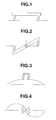
- Fig. 1 is an explanatory view for explaining a first order bending vibration mode in a dynamic damper.
- Fig. 2 is an explanatory view for explaining a second order bending vibration mode in the dynamic damper.
- Fig. 3 is an explanatory view for explaining the first order bending vibration mode in a case of a tube member.
- Fig. 4 is an explanatory view for explaining the second order bending vibration of the tube member.
- Fig. 5 is a cross-sectional view of a comparative example of a dynamic damper.
- Fig. 6 is a model view representing a modeled comparative example of the dynamic damper shown in Fig. 5.
- Fig. 7 is a cross sectional view of a torque transmissible tube member to which a dynamic damper according to the present invention is applicable.
- Fig. 8 is a characteristic graph representing a damping effect of the comparative example of the dynamic damper shown in Fig. 5.
- Fig. 9 is a cross sectional view representing a structure of a dynamic damper in a first preferred embodiment according to the present invention.
- Fig. 10 is a characteristic graph representing a damping effect of the dynamic damper shown in Fig. 9.
- Fig. 11 is a cross-sectional view of the dynamic damper in a second preferred embodiment according to the present invention.
- Fig. 12 is a cross-sectional view of the dynamic damper in a third preferred embodiment according to the present invention.
- Fig. 13 is a cross-sectional view of the dynamic damper in a fourth preferred embodiment according to the present invention.
- Fig. 14 is a cross-sectional view of the dynamic damper in a fifth preferred embodiment according to the present invention.
- a basic concept of a dynamic damper according to the present invention will be described below.
- a ratio of specific values of bending first order (or primary) resonance and bending second order (or secondary) resonance of a tube member such as a torque transmission tube (or torque transmissible tube member) will be described below. That is to say, if the dynamic damper has the same resonance specific value ratio as a ratio of the specific values of the bending first-order resonance and the bending second-order resonance, it can be expected that a single dynamic damper can damp both of the bending vibrations in the first order and in the second order.
- a term of "a higher order” in the appended claims points to a second order side with respect to a first order side and, in general, points to one of two degrees (order values) which is larger than the other degree (order value).
- the resonance specific values of the two bending first-order/second-order vibration modes in bending directions as shown in Figs. 1 and 2 that the dynamic damper naturally has are made coincident with those of the bending first-order modes and bending second-order modes of the tube member as shown in Figs. 3 and 4 so that the single dynamic damper can damp the vibrations caused by two resonance points.
- Fdr denotes the resonance specific value in a case where the whole mass member of the dynamic damper is displaced in the same phase (first order mode)
- Fd ⁇ denotes the resonance specific value in a case where both ends of the mass member of the dynamic damper are mutually displaced in an opposite phase (second order mode)
- Fd ⁇ /Fdr denotes the resonance specific value ratio of the above-described two displacement modes of the dynamic damper.
- Fig. 6 is a representation of a vibration model of dynamic damper 1 shown in Fig. 1.
- M denotes a mass of mass member 2
- I denotes an inertia moment around a weight center of mass member 2
- K denotes a rigidity of elastic member 3.
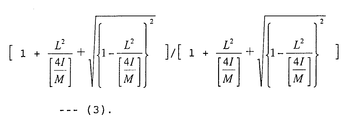
- a natural vibration frequency of the vibration model shown in Fig. 6 is expressed in the following equation.
- the resonance specific value ratio can be expressed as follows: In the equation (3), ⁇ (1) ⁇ ⁇ (2).
- Equation (3) is arranged as follows:
- the resonance specific value ratio is less than 1.73 in spite of the fact of its length of mass member 2 and its outer diameter thereof. Hence, the resonance specific value ratio of mass member 2 in the hollow cylindrical shape of dynamic damper 1 is less than 2. 7. Using this shape shown in Fig. 5, both of the bending first-order and the bending second-order resonances of tube member 4 cannot be damped.
- Fig. 9 shows a dynamic damper in a first preferred embodiment according to the present invention.
- Dynamic damper 1 is supported by means of pair of elastic members 3a and 3b at both ends of mass member 2 disposed concentrically to tube member 4 and on a center axis of tube member 4.
- dynamic damper 1 is provided with a large mass section 2b projected toward an outer peripheral side of mass member 2, located at a center portion in a center axis (namely, center axis of tube member 4) of mass member 2 having a hollow cylindrically shaped basic shape portion 2a in order to reduce weight thereof, and disposed in a ring shape.
- large mass section 2b is integrally formed with basic shape portion 2a using the same material as the other position of mass member 2 and is constructed in such a way that a difference in its cross-sectional area causes the mass to be enlarged.
- the present invention is not limited to this. Different materials as those other portions of basic shape portion 2a may be used for the center portion which forms large mass section 2b.
- dynamic damper 1 may be formed merely in the cylindrical form, its center portion may use a material having a larger specific gravity than another material of which the other portion of basic shape portion 2a is formed. In this case, a degree of freedom in setting the shape of mass member 2 can be increased.
- axis described hereinafter denotes the center axis of tube member 4, viz., points to the center axis of dynamic damper 1.
- a shape of mass member 2 is such that a length in the axial direction thereof is longer than a diameter of large mass section 2b.
- a rotation center of the bending second-order vibration mode of dynamic damper 1 shown in Fig. 9 in other words, a center position between the pair of elastic members 3a and 3b is made coincident with a node of the bending second-order vibration mode of tube member 4 shown in Fig. 7.
- the center portion in the axial direction of mass member 2 (large mass section 2b) is heavier than any other portions so that an inertia moment around the weight center of dynamic damper 1 shown in Fig. 9 is reduced with respect to the mass and the resonance specific value ratio that dynamic damper 1 shown in Fig. 9 has can be augmented.
- the resonance specific value ratio is 3.2 for the shape of dynamic damper 1 shown in Fig. 9 so that the damping effect can be provided for both of the bending first-order and second-order resonances.
- the rotation center of dynamic damper 1 can be made coincident with the node of the bending second-order mode of tube member 4.
- the damping effect can furthermore be improved.
- the rotation center (large mass section 2b) of dynamic damper 1 is made coincident with the node of the bending second-order mode of tube member 4, it is not always for the rotation center to be made coincident with the node described above in order to obtain the above-described effects. For example, if the rotation center is set between pair of elastic members 3a and 3b via which mass member 2 is linked to tube member 4, as shown in Fig.
- Fig. 10 shows another result of the FEM analysis of the damping effects for the bending first-order and second-order resonances of tube member 4 in a case where dynamic damper 1 shown in Fig. 9 is mounted on tube member 4 corresponding to the vehicular propeller shaft.
- Fig. 10 shows another result of the FEM analysis of the damping effects for the bending first-order and second-order resonances of tube member 4 in a case where dynamic damper 1 shown in Fig. 9 is mounted on tube member 4 corresponding to the vehicular propeller shaft.
- Fig. 11 shows a second preferred embodiment of dynamic damper 1.
- basic shape section 2a of dynamic damper 1 in the first embodiment shown in Fig. 9 is of a solid cylindrical shape (not in the hollow cylindrical shape).
- Fig. 12 shows a third preferred embodiment of dynamic damper 1.
- large mass section 2b projected toward the inner peripheral side of mass member 2 is installed at the axial center of mass member 2 having hollow cylindrical basic shape portion 2a so that the maximum value of the mass distribution of dynamic damper 1 is set at the axial center of dynamic damper 1. even if such a structure as described in the third embodiment of dynamic damper with reference to Fig.
- the shape of dynamic damper 1 is set in such a way that its axial center gives maximum in the mass distribution so that dynamic damper 1 enlarges the ratio of the specific value of the bending first-order and second-order resonances by the single dynamic damper 1 and can damp the vibrations due to the bending first order and second order resonances of tube member 4 described above.
- Fig. 13 shows a fourth preferred embodiment of dynamic damper 1 according to the present invention.
- the shape of mass member 2 includes: a hollow cylindrical portion 2a with an axis 4a of tube member 4 as a center; a ring section 2b concentrically disposed on the axial center of hollow cylindrical portion 2a with axis 4a of tube member 4 as a center; and a linkage section 2c to link the cylindrical portion 2a and ring section 2b and having a smaller axial dimension than ring section 2b.
- a further light-weight mass member 2 can be achieved while maintaining the damping effects to the vibrations caused by the bending first-order and second-order resonances of tube member 4.
- Fig. 14 shows a fifth embodiment of dynamic damper according to the present invention.
- large mass section 2b set at the axial center of mass member 2 in the case of either dynamic damper 1 in the first or second embodiment is, in turn, arranged with the offset from the axial center of mass member 2.
- the damping effect for the torsional vibration of tube member 4 can be generated together with achieving the damping effects of the vibration due to the bending first-order and second-order resonances of tube member 4.
- the structure of dynamic damper 1 is set so that the vibrations due to the bending first-order and second-order resonances of tube member 4 are damped.
- the structure of the dynamic damper can be set so as to obtain the damping effect of the vibrations due to the resonance in other orders (degrees).
Landscapes
- Engineering & Computer Science (AREA)
- General Engineering & Computer Science (AREA)
- Physics & Mathematics (AREA)
- Acoustics & Sound (AREA)
- Aviation & Aerospace Engineering (AREA)
- Mechanical Engineering (AREA)
- Vibration Prevention Devices (AREA)
- Motor Power Transmission Devices (AREA)
- Vibration Dampers (AREA)
Abstract
Description





Claims (25)
- A dynamic damper (1) comprising:a torque transmissible tube member (4);a mass member (2) housed within the inside of the tube member concentrically to the tube member; anda pair of elastic members (3a, 3b), both ends of the mass member in a center axis direction of the tube member being coupled to the tube member via the pair of elastic members, the mass member including a large mass section (2b) formed between the pair of elastic members, the length of the mass member in the center axis direction of the tube member being longer than a diameter of the large mass section, and, from among two different bending resonance vibration modes of the tube member, a node of a higher order bending resonance vibration mode being placed at a position between the pair of elastic members.
- A dynamic damper as claimed in claim 1, wherein the large mass section (2b) is formed on a center of the mass member between the pair of elastic members.
- A dynamic damper as claimed in claim 1, wherein the large mass section (2b) is formed at the position between the pair of elastic members which is offset from a center between the pair of elastic members.
- A dynamic damper as claimed in either claim 2 or claim 3, wherein the mass member (2) is formed in a solid cylindrical shape with a center axis of the tube member as a center and the outer diameter of the large mass section (2b) is longer than that of any other portion of the mass member.
- A dynamic damper as claimed in either claim 2 or claim 3, wherein the mass member is formed in a hollow cylindrical shape with a center axis of the tube member as a center and the outer diameter of the large mass section is longer than that of any other portion of the mass member.
- A dynamic damper as claimed in either claim 2 or claim 3, wherein the mass member comprises: a hollow cylindrical shape section (2a) with a center axis of the tube member as a center; a ring section (2b) arranged concentrically to the center axis of the tube member; and a linkage section (2c) that links the hollow cylindrical shape section with the ring section and has an axial dimension smaller than the ring section.
- A dynamic damper as claimed in either claim 2 or claim 3, wherein the mass member is formed in a cylindrical shape with a center axis of the tube member as a center and the large mass section is formed of a material having a larger specific gravity than that of any other portion of the mass member.
- A dynamic damper as claimed in either claim 2 or claim 3, wherein the mass member is formed in a hollow cylindrical shape with a center axis of the tube member as a center and the large mass section is formed in a solid cylindrical shape whose outer diameter is equal to that of any other portion of the mass member.
- A dynamic damper (1) comprising:a torque transmissible tube member (4);a mass member (2) housed within the inside of the tube member concentrically to the tube member; anda pair of elastic members (3a, 3b), both ends of the mass member in a center axis direction of the tube member being coupled to the tube member via the pair of elastic members, the length of the tube member in the center axis direction thereof being longer than a diameter of the mass member, the mass member including a large mass section (2b) formed between the pair of elastic members and having a mass larger than any other portion of the mass member, and the pair of elastic members being arranged in such a manner that, from among two different bending resonance vibration modes of the tube member, a node of a higher order bending resonance vibration mode is made coincident with a center between the pair of elastic members.
- A dynamic damper as claimed in claim 9, wherein the large mass section (2b) is formed on the center between the pair of elastic members.
- A dynamic damper as claimed in claim 9, wherein the large mass section (2b) is formed at a position between the pair of elastic members which is offset from the center between the pair of elastic members.
- A dynamic damper as claimed in either claim 10 or claim 11, wherein the mass member is formed in a solid cylindrical shape with a center axis of the tube member as a center and the outer diameter of the large mass section (2b) is longer than that of any other portion of the mass member.
- A dynamic damper as claimed in either claim 10 or claim 11, wherein the mass member is formed in a hollow cylindrical shape with a center axis of the tube member as a center and the outer diameter of the large mass section is longer than that of any other portion of the mass member.
- A dynamic damper as claimed in either claim 10 or claim 11, wherein the mass member is formed in a cylindrical shape with the center axis of the tube member as a center and the large mass section is formed of a material having a larger specific gravity than that of any other portion of the mass member.
- A dynamic damper as claimed in either claim 10 or claim 11, wherein the mass member is formed in a hollow cylindrical shape with a center axis of the tube member as a center and the large mass section is formed in a solid cylindrical shape whose outer diameter is equal to that of any other portion of the mass member.
- A dynamic damper (1) comprising:a torque transmissible tube member (4);a mass member (2) housed within the inside of the tube member concentrically with respect to the tube member; anda pair of elastic members (3a. 3b), both ends of the mass member in a center axis direction of the tube member being coupled to the tube member via the pair of elastic members, the length of the tube member in the center axis direction thereof being longer than a diameter of the mass member, the mass member including a large mass section formed between the pair of elastic members and having a mass larger than any other portion of the mass member, and the pair of elastic members being arranged in such a manner that, from among first-order and second-order bending resonance vibration modes of the tube member, anode of the second-order bending resonance vibration mode is made coincident with a center between the pair of elastic members.
- A dynamic damper as claimed in claim 16, wherein the large mass section is formed on the center between the pair of elastic members.
- A dynamic damper as claimed in claim 16, wherein the large mass section is formed at a position between the pair of elastic members which is offset from the center between the pair of elastic members.
- A dynamic damper as claimed in either claim 17 or claim 18, wherein the mass member is formed in a solid cylindrical shape (2a) with a center axis of the tube member as a center and the outer diameter of the large mass section is longer than that of any other portion of the mass member.
- A dynamic damper as claimed in either claim 17 or claim 18, wherein the mass member is formed in a hollow cylindrical shape with a center axis of the tube member as a center and the outer diameter of the large mass section is longer than that of any other portion of the mass member.
- A dynamic damper as claimed in either claim 17 or claim 18, wherein the mass member comprises: a hollow cylindrical shape section (2a) with a center axis of the tube member as a center; a ring section (2b) arranged concentrically to the center axis of the tube member; and a linkage section (2c) that links the hollow cylindrical shape section with the ring section and has an axial dimension smaller than the ring section.
- A dynamic damper as claimed in either claim 17 or claim 18, wherein the mass member is formed in a cylindrical shape with a center axis of the tube member as a center and the large mass section is formed of a material having a larger specific gravity than that of any other portion of the mass member.
- A dynamic damper as claimed in either claim 17 or claim 18, wherein the mass member is formed in a hollow cylindrical shape with a center axis of the tube member as a center and the large mass section is formed in a solid cylindrical shape whose outer diameter is equal to that of any other portion of the mass member.
- A dynamic damper (1) comprising:a torque transmissible tube member (4);a mass member (2) housed within the inside of the tube member concentrically with respect to the tube member; anda pair of elastic members (3a, 3b), both ends of the mass member in a center axis direction of the tube member being coupled to the tube member via the pair of elastic members and the length of the tube member in the center axis direction thereof being longer than a diameter of the mass member and the mass member including a large mass section formed on a center portion between the pair of elastic members to set a ratio of different two specific values of resonances that the dynamic damper has to a range between 2.7 and 6.3 and to place, from among two different bending resonance vibration modes of the tube member, a node of a higher order bending resonance vibration mode at a position between the pair of elastic members.
- A dynamic damper (1) comprising:a torque transmissible tube member (4);a mass member (2) housed within the inside of the tube member concentrically with respect to the tube member; anda pair of elastic members (3a, 3b), both ends of the mass member in a center axis direction of the tube member being coupled to the tube member via the pair of elastic members and the length of the tube member in the center axis direction thereof being longer than a diameter of the mass member and the mass member including a large mass section formed on a center portion between the pair of elastic members to set a ratio of different two specific values of resonances that the dynamic damper has to a range between 2.7 and 6.3 and to place, from among first-order and second-order bending resonance vibration modes of the tube member, a node of the second-order bending resonance vibration mode at a position between the pair of elastic members.
Applications Claiming Priority (2)
| Application Number | Priority Date | Filing Date | Title |
|---|---|---|---|
| JP2002033589A JP3797239B2 (en) | 2002-02-12 | 2002-02-12 | Multi-degree-of-freedom dynamic damper |
| JP2002033589 | 2002-02-12 |
Publications (3)
| Publication Number | Publication Date |
|---|---|
| EP1335150A2 true EP1335150A2 (en) | 2003-08-13 |
| EP1335150A3 EP1335150A3 (en) | 2004-07-28 |
| EP1335150B1 EP1335150B1 (en) | 2006-06-14 |
Family
ID=27606559
Family Applications (1)
| Application Number | Title | Priority Date | Filing Date |
|---|---|---|---|
| EP03250530A Expired - Lifetime EP1335150B1 (en) | 2002-02-12 | 2003-01-29 | Dynamic damper with multiple degree of freedom |
Country Status (4)
| Country | Link |
|---|---|
| US (1) | US7192357B2 (en) |
| EP (1) | EP1335150B1 (en) |
| JP (1) | JP3797239B2 (en) |
| DE (1) | DE60305990T2 (en) |
Cited By (2)
| Publication number | Priority date | Publication date | Assignee | Title |
|---|---|---|---|---|
| CN107606054A (en) * | 2017-10-23 | 2018-01-19 | 苏州大学 | A kind of self-adapting type torsional vibration damper and diesel engine |
| CN111237388A (en) * | 2018-11-29 | 2020-06-05 | 长城汽车股份有限公司 | Transmission shaft structure and vehicle |
Families Citing this family (14)
| Publication number | Priority date | Publication date | Assignee | Title |
|---|---|---|---|---|
| US6752722B2 (en) * | 2002-03-13 | 2004-06-22 | American Axle & Manufacturing, Inc. | Foam lined propshaft |
| US20070072688A1 (en) * | 2005-07-13 | 2007-03-29 | Dickson John A | Driveshaft system |
| US7549927B2 (en) * | 2006-09-25 | 2009-06-23 | Automotive Components Holdings, Llc | Tunable damper for a torque transferring assembly |
| JP5887726B2 (en) * | 2011-06-22 | 2016-03-16 | マツダ株式会社 | Method of setting dynamic damper for vehicle and mounting structure of dynamic damper for vehicle |
| JP5420601B2 (en) * | 2011-07-25 | 2014-02-19 | 株式会社日立ハイテクノロジーズ | Charged particle equipment |
| DE102012202250A1 (en) * | 2012-02-15 | 2013-08-22 | Zf Friedrichshafen Ag | Shaft e.g. countershaft, has resilient cylindrical damping element, and vibration damper formed as axial vibration dampers, where damping element is arranged directly or indirectly in non-positive manner at wall of axial bore |
| US9033807B1 (en) | 2013-10-30 | 2015-05-19 | American Axle & Manufacturing, Inc. | Propshaft assembly with damper |
| US8832941B1 (en) | 2013-11-14 | 2014-09-16 | Cardinal Machine Company | Method for assembling a propshaft assembly |
| US8863390B1 (en) | 2014-04-16 | 2014-10-21 | American Axle & Manufacturing, Inc. | Method for fabricating damped propshaft assembly |
| US9759278B2 (en) | 2015-12-21 | 2017-09-12 | Goodrich Corporation | Multi-piece torque tube assembly to mitigate vibration |
| US11485507B2 (en) * | 2016-12-20 | 2022-11-01 | Bombardier Inc. | Thrust link with tuned absorber |
| US20180202485A1 (en) * | 2017-01-13 | 2018-07-19 | GM Global Technology Operations LLC | Prop-shaft for a vehicle |
| US10677312B2 (en) | 2018-02-15 | 2020-06-09 | General Electric Company | Friction shaft damper for axial vibration mode |
| US11761512B1 (en) * | 2020-07-16 | 2023-09-19 | The United States Of America, As Represented By The Secretary Of The Navy | Biaxial vibration isolation and damping in a concentric plural-cylinder system |
Family Cites Families (14)
| Publication number | Priority date | Publication date | Assignee | Title |
|---|---|---|---|---|
| US1776125A (en) * | 1928-09-17 | 1930-09-16 | Gen Electric | Method of and means for balancing rotors |
| US3075408A (en) | 1959-08-19 | 1963-01-29 | Gen Motors Corp | Drive axle transmission |
| US3075406A (en) * | 1961-07-13 | 1963-01-29 | Gen Motors Corp | Propeller shaft damper |
| GB1462170A (en) | 1975-08-27 | 1977-01-19 | Ford Motor Co | Drive shaft dynamic damper |
| DE2747225C2 (en) * | 1977-10-21 | 1982-04-22 | Dr.Ing.H.C. F. Porsche Ag, 7000 Stuttgart | Drive unit elastically mounted in a motor vehicle |
| DE3125830C1 (en) | 1981-07-01 | 1983-02-03 | Dr.Ing.H.C. F. Porsche Ag, 7000 Stuttgart | In a motor vehicle elastically mounted drive unit |
| JPS6327743U (en) * | 1986-08-07 | 1988-02-23 | ||
| JP3200738B2 (en) | 1990-01-31 | 2001-08-20 | 鬼怒川ゴム工業株式会社 | Dynamic damper |
| JPH0729324Y2 (en) * | 1990-06-28 | 1995-07-05 | スズキ株式会社 | Propeller shaft |
| JP2599059B2 (en) * | 1991-11-25 | 1997-04-09 | 東海ゴム工業株式会社 | Dynamic damper for hollow drive shaft |
| US6033312A (en) * | 1996-10-10 | 2000-03-07 | Sikorsky Aircraft Corporation | Method and apparatus for controlling lateral vibration in a rotating shaft |
| JP2001021002A (en) * | 2000-01-01 | 2001-01-26 | Kinugawa Rubber Ind Co Ltd | Dynamic damper |
| JP2001260681A (en) | 2000-03-15 | 2001-09-26 | Tokai Rubber Ind Ltd | Dynamic damper and propeller shaft |
| US6752722B2 (en) * | 2002-03-13 | 2004-06-22 | American Axle & Manufacturing, Inc. | Foam lined propshaft |
-
2002
- 2002-02-12 JP JP2002033589A patent/JP3797239B2/en not_active Expired - Fee Related
-
2003
- 2003-01-21 US US10/347,453 patent/US7192357B2/en not_active Expired - Fee Related
- 2003-01-29 DE DE60305990T patent/DE60305990T2/en not_active Expired - Lifetime
- 2003-01-29 EP EP03250530A patent/EP1335150B1/en not_active Expired - Lifetime
Cited By (2)
| Publication number | Priority date | Publication date | Assignee | Title |
|---|---|---|---|---|
| CN107606054A (en) * | 2017-10-23 | 2018-01-19 | 苏州大学 | A kind of self-adapting type torsional vibration damper and diesel engine |
| CN111237388A (en) * | 2018-11-29 | 2020-06-05 | 长城汽车股份有限公司 | Transmission shaft structure and vehicle |
Also Published As
| Publication number | Publication date |
|---|---|
| JP2003232406A (en) | 2003-08-22 |
| EP1335150B1 (en) | 2006-06-14 |
| US20030153391A1 (en) | 2003-08-14 |
| EP1335150A3 (en) | 2004-07-28 |
| DE60305990D1 (en) | 2006-07-27 |
| US7192357B2 (en) | 2007-03-20 |
| JP3797239B2 (en) | 2006-07-12 |
| DE60305990T2 (en) | 2007-02-01 |
Similar Documents
| Publication | Publication Date | Title |
|---|---|---|
| US7192357B2 (en) | Dynamic damper with multiple degree of freedom | |
| JP3538479B2 (en) | Double mass dynamic damper and drive axle with dynamic damper | |
| JP2599059B2 (en) | Dynamic damper for hollow drive shaft | |
| US5996959A (en) | Vibration damper | |
| US4889328A (en) | Insulator for use in automotive suspension or the like | |
| RU2505424C1 (en) | Three-cylinder engine | |
| US20140367547A1 (en) | Engine mount and power unit vibration damping support structure | |
| KR102072020B1 (en) | Torsional vibration damping device | |
| JPS6327205B2 (en) | ||
| JP6573037B2 (en) | Vibration damping device | |
| EP0087569B1 (en) | Low vibration-level remote control gearshift linkage for manual transmission | |
| JP2003040112A (en) | Dynamic damper device for steering | |
| JP4114209B2 (en) | damper | |
| JP3200738B2 (en) | Dynamic damper | |
| JPH10122303A (en) | Lateral vibration control device and control method for rotating shaft | |
| JPH11351247A (en) | Anti-vibration structure of propeller shaft | |
| JP6137670B2 (en) | Damper device | |
| JP2008002677A (en) | Cylindrical dynamic damper | |
| JPH0914350A (en) | Torsional vibration damping device and damping method | |
| JPH10278604A (en) | Torque transmission shaft and propeller shaft | |
| JP2009012598A (en) | Power unit mounting device and pendulum mounting system | |
| JP2020139563A (en) | Torsional vibration reduction device | |
| JP2004084681A (en) | Damper mechanism and flywheel damper | |
| CN114623196B (en) | Transmission device | |
| JP4535262B2 (en) | Torque rod |
Legal Events
| Date | Code | Title | Description |
|---|---|---|---|
| PUAI | Public reference made under article 153(3) epc to a published international application that has entered the european phase |
Free format text: ORIGINAL CODE: 0009012 |
|
| 17P | Request for examination filed |
Effective date: 20030226 |
|
| AK | Designated contracting states |
Designated state(s): AT BE BG CH CY CZ DE DK EE ES FI FR GB GR HU IE IT LI LU MC NL PT SE SI SK TR |
|
| AX | Request for extension of the european patent |
Extension state: AL LT LV MK RO |
|
| PUAL | Search report despatched |
Free format text: ORIGINAL CODE: 0009013 |
|
| AK | Designated contracting states |
Kind code of ref document: A3 Designated state(s): AT BE BG CH CY CZ DE DK EE ES FI FR GB GR HU IE IT LI LU MC NL PT SE SI SK TR |
|
| AX | Request for extension of the european patent |
Extension state: AL LT LV MK RO |
|
| RIC1 | Information provided on ipc code assigned before grant |
Ipc: 7F 16F 15/14 B Ipc: 7F 16F 7/108 A |
|
| AKX | Designation fees paid |
Designated state(s): DE FR GB |
|
| 17Q | First examination report despatched |
Effective date: 20050502 |
|
| GRAP | Despatch of communication of intention to grant a patent |
Free format text: ORIGINAL CODE: EPIDOSNIGR1 |
|
| GRAS | Grant fee paid |
Free format text: ORIGINAL CODE: EPIDOSNIGR3 |
|
| GRAA | (expected) grant |
Free format text: ORIGINAL CODE: 0009210 |
|
| AK | Designated contracting states |
Kind code of ref document: B1 Designated state(s): DE FR GB |
|
| REG | Reference to a national code |
Ref country code: GB Ref legal event code: FG4D |
|
| REF | Corresponds to: |
Ref document number: 60305990 Country of ref document: DE Date of ref document: 20060727 Kind code of ref document: P |
|
| ET | Fr: translation filed | ||
| PLBE | No opposition filed within time limit |
Free format text: ORIGINAL CODE: 0009261 |
|
| STAA | Information on the status of an ep patent application or granted ep patent |
Free format text: STATUS: NO OPPOSITION FILED WITHIN TIME LIMIT |
|
| 26N | No opposition filed |
Effective date: 20070315 |
|
| PGFP | Annual fee paid to national office [announced via postgrant information from national office to epo] |
Ref country code: DE Payment date: 20140122 Year of fee payment: 12 |
|
| PGFP | Annual fee paid to national office [announced via postgrant information from national office to epo] |
Ref country code: FR Payment date: 20140108 Year of fee payment: 12 |
|
| PGFP | Annual fee paid to national office [announced via postgrant information from national office to epo] |
Ref country code: GB Payment date: 20140129 Year of fee payment: 12 |
|
| REG | Reference to a national code |
Ref country code: DE Ref legal event code: R119 Ref document number: 60305990 Country of ref document: DE |
|
| GBPC | Gb: european patent ceased through non-payment of renewal fee |
Effective date: 20150129 |
|
| PG25 | Lapsed in a contracting state [announced via postgrant information from national office to epo] |
Ref country code: GB Free format text: LAPSE BECAUSE OF NON-PAYMENT OF DUE FEES Effective date: 20150129 Ref country code: DE Free format text: LAPSE BECAUSE OF NON-PAYMENT OF DUE FEES Effective date: 20150801 |
|
| REG | Reference to a national code |
Ref country code: FR Ref legal event code: ST Effective date: 20150930 |
|
| PG25 | Lapsed in a contracting state [announced via postgrant information from national office to epo] |
Ref country code: FR Free format text: LAPSE BECAUSE OF NON-PAYMENT OF DUE FEES Effective date: 20150202 |