EP1335055A1 - Weft feeder for textile machines with improved system for attaching the stationary drum to the motor housing - Google Patents
Weft feeder for textile machines with improved system for attaching the stationary drum to the motor housing Download PDFInfo
- Publication number
- EP1335055A1 EP1335055A1 EP03001608A EP03001608A EP1335055A1 EP 1335055 A1 EP1335055 A1 EP 1335055A1 EP 03001608 A EP03001608 A EP 03001608A EP 03001608 A EP03001608 A EP 03001608A EP 1335055 A1 EP1335055 A1 EP 1335055A1
- Authority
- EP
- European Patent Office
- Prior art keywords
- drum
- annular surface
- magnets
- motor housing
- swivel arm
- Prior art date
- Legal status (The legal status is an assumption and is not a legal conclusion. Google has not performed a legal analysis and makes no representation as to the accuracy of the status listed.)
- Granted
Links
- 239000004753 textile Substances 0.000 title claims abstract description 4
- 230000005294 ferromagnetic effect Effects 0.000 claims abstract description 11
- 229910052779 Neodymium Inorganic materials 0.000 claims abstract description 3
- QEFYFXOXNSNQGX-UHFFFAOYSA-N neodymium atom Chemical compound [Nd] QEFYFXOXNSNQGX-UHFFFAOYSA-N 0.000 claims abstract description 3
- 230000000284 resting effect Effects 0.000 claims description 2
- 230000004907 flux Effects 0.000 abstract description 3
- 230000009977 dual effect Effects 0.000 abstract description 2
- 230000005291 magnetic effect Effects 0.000 description 6
- 238000004804 winding Methods 0.000 description 3
- 230000000295 complement effect Effects 0.000 description 2
- 238000009940 knitting Methods 0.000 description 2
- 238000012423 maintenance Methods 0.000 description 2
- 238000004519 manufacturing process Methods 0.000 description 2
- 238000000465 moulding Methods 0.000 description 2
- 229910000859 α-Fe Inorganic materials 0.000 description 2
- 239000000463 material Substances 0.000 description 1
- 229910052751 metal Inorganic materials 0.000 description 1
- 239000002184 metal Substances 0.000 description 1
- 238000000034 method Methods 0.000 description 1
- 229910001172 neodymium magnet Inorganic materials 0.000 description 1
- 230000002093 peripheral effect Effects 0.000 description 1
- 230000009467 reduction Effects 0.000 description 1
- 238000005245 sintering Methods 0.000 description 1
- 125000006850 spacer group Chemical group 0.000 description 1
Images

Classifications
-
- D—TEXTILES; PAPER
- D04—BRAIDING; LACE-MAKING; KNITTING; TRIMMINGS; NON-WOVEN FABRICS
- D04B—KNITTING
- D04B15/00—Details of, or auxiliary devices incorporated in, weft knitting machines, restricted to machines of this kind
- D04B15/38—Devices for supplying, feeding, or guiding threads to needles
- D04B15/48—Thread-feeding devices
- D04B15/482—Thread-feeding devices comprising a rotatable or stationary intermediate storage drum from which the thread is axially and intermittently pulled off; Devices which can be switched between positive feed and intermittent feed
-
- D—TEXTILES; PAPER
- D03—WEAVING
- D03D—WOVEN FABRICS; METHODS OF WEAVING; LOOMS
- D03D47/00—Looms in which bulk supply of weft does not pass through shed, e.g. shuttleless looms, gripper shuttle looms, dummy shuttle looms
- D03D47/34—Handling the weft between bulk storage and weft-inserting means
-
- D—TEXTILES; PAPER
- D03—WEAVING
- D03D—WOVEN FABRICS; METHODS OF WEAVING; LOOMS
- D03D47/00—Looms in which bulk supply of weft does not pass through shed, e.g. shuttleless looms, gripper shuttle looms, dummy shuttle looms
- D03D47/34—Handling the weft between bulk storage and weft-inserting means
- D03D47/36—Measuring and cutting the weft
- D03D47/361—Drum-type weft feeding devices
- D03D47/364—Yarn braking means acting on the drum
-
- D—TEXTILES; PAPER
- D03—WEAVING
- D03D—WOVEN FABRICS; METHODS OF WEAVING; LOOMS
- D03D47/00—Looms in which bulk supply of weft does not pass through shed, e.g. shuttleless looms, gripper shuttle looms, dummy shuttle looms
- D03D47/34—Handling the weft between bulk storage and weft-inserting means
- D03D47/36—Measuring and cutting the weft
- D03D47/361—Drum-type weft feeding devices
- D03D47/364—Yarn braking means acting on the drum
- D03D47/366—Conical
Definitions
- This invention relates to a weft feeder for textile machines, particularly knitting machines, provided with an improved system for fixing the stationary drum onto the motor housing.
- weft feeders for knitting machines comprise a stationary drum on which a swivel arm, driven by a motor, winds multiple loops of thread, which constitute a weft reserve.
- the motor shaft is hollow, so that the thread can pass within it; the thread then exits through a slot provided at an intermediate section of the shaft and is sent to a guide located at the end of the swivel arm for winding on the drum.
- the loops of thread unwind from the drum and are supplied to the loom after passing through a braking means that controls the mechanical tension of the thread in order to maintain it substantially constant.
- a device for fixing the drum to the motor housing having two complementary frustum-shaped rings on which permanent magnets with mutually opposite polarities are agglomerated, one ring being attached at the end of the motor housing, the other ring being attached to the drum.
- This device for fixing the drum to the motor housing has drawbacks, the first of which is that, for example due to temperature variations that occur during molding operations, or due to impacts during assembly/disassembly and maintenance of the device, the magnets may break, be damaged or be partially demagnetized; such accidents necessarily cause replacement of the entire ring, with attendant penalties concerning maintenance times and costs.
- the main object of this invention is therefore to provide a weft feeder equipped with a system for securely fixing the stationary drum to the motor housing, while allowing, in case of damage or incorrect assembly of some of its parts, the replacement of the damaged parts only.
- Another object of the invention is to provide said device so that the system for fixing the drum to the motor housing has a smaller bulk and weight than known systems.
- Another object of the invention is to provide said device so that it can be manufactured easily and at a low cost, by means of equipment that is conventional in the field.
- a generic weft feeder generally designated by the reference numeral 10, comprises a motor housing 11 and a stationary drum 12, on which a frustum-shaped circular swivel arm 13, keyed on a motor shaft 14 driven by a motor M, winds multiple loops of thread F, which constitute a weft reserve RT.
- motor shaft 14 is hollow, so that thread F can pass through it; the thread exits through a slot 15 provided at an intermediate section of shaft 14, and is sent to a guiding hole 16 provided in a peripheral region of the disk that constitutes the arm 13 in order to be wound onto the drum 12.
- the loops unwind from drum 12 and are fed to the loom, passing through a braking means 17 that controls the mechanical tension of thread F in order to keep it substantially constant.
- the fixing system has a set of first permanent magnets, such as 18a, which are detachably received in respective first recessed seats such as 19a, provided with a ferromagnetic plate 21a on their bottoms and arranged on a first annular surface 26 which is concave and frustum-shaped and is formed coaxially at the end of motor housing 11.
- each of the ferromagnetic plates 21a is attached by means of a screw 25a to the first annular surface 26 and is provided with a rim 22, forming the edge of the resting surface of the magnet, in order to retain a bushing 23 made of plastic material, which has, for this purpose, a corresponding inside edge 24 at one axial end, shaped to surround the respective permanent magnet 18a.
- Second permanent magnets such as 18b, having opposite polarities, are arranged opposite the first magnets and are also received in respective second seats such as 19b, provided with ferromagnetic plates 21b on their bottoms and arranged on a second annular convex frustum-shaped surface 20, which is complementary to surface 26 and is formed on a support 27 which is attached to the base of drum 12.
- the second seats are preferably formed as cavities 19b made in the second annular surface 20; the ferromagnetic plates 21b are attached to the bottoms of said cavities by means of screws 25b.
- Elongated centering brackets such as 35 and centering/attaching brackets such as 36 extend from support 27, parallelly to axis H, and receive nuts 37 which allow drum 12 to be connected to support 27 by means of screws 38.
- Swivel arm 13 is keyed to the motor shaft 14 so that its hub 28 is sandwiched between the internal rotating rings of bearings 29, 30a, 30b, which themselves abut on shoulders 31, 32, respectively.
- Bearings 29, 30a, 30b are received in seats 33, 34 formed respectively within the motor housing 11 and on the internal cylindrical surface of the support 27.
- Neodymium magnets 18a, 18b are particularly suitable for the purposes of the present invention, since they possess, for equal sizes, a magnetic capacity up to ten times greater than the more commonly used ferrite magnets.
- a steady connection of the parts is obtained, while a free volume is left between them as required for the passage of the swivel arm and the winding of the thread onto the drum.
- Ferromagnetic plates 21a and 21b therefore perform the dual function of retaining the respective magnets 18a, 18b in their seats and of conveying their lines of flux into the region of interest where arm 13 rotates.
- the invention fully achieves the intended aim, by providing a weft feeder having a system for securely attaching the drum to the motor housing, which system also allows each individual magnet to be replaced quickly and independently in case of damage or incorrect assembly, while complying with the required alternation of the polarities. Therefore, with the device according to the invention it is possible, if case of break of a magnet, to recover the remaining ones, with obvious cost advantages.
- Another advantage of the device according to the invention is that it has a smaller bulk and a lower weight than known devices, the high magnetic capacity of neodymium being exploited not only for securely attaching the magnets to the respective seats and for achieving a more stable connection between the drum and the motor housing, but also for reducing the number and sizes of said magnets.
- Another advantage of said device is that it has a low manufacturing cost and is simple to manufacture by means of equipment that is common in the field.
Landscapes
- Engineering & Computer Science (AREA)
- Textile Engineering (AREA)
- Looms (AREA)
- Forwarding And Storing Of Filamentary Material (AREA)
Abstract
Description
- This invention relates to a weft feeder for textile machines, particularly knitting machines, provided with an improved system for fixing the stationary drum onto the motor housing.
- As is known, weft feeders for knitting machines comprise a stationary drum on which a swivel arm, driven by a motor, winds multiple loops of thread, which constitute a weft reserve. For this purpose, the motor shaft is hollow, so that the thread can pass within it; the thread then exits through a slot provided at an intermediate section of the shaft and is sent to a guide located at the end of the swivel arm for winding on the drum. When requested by the loom, the loops of thread unwind from the drum and are supplied to the loom after passing through a braking means that controls the mechanical tension of the thread in order to maintain it substantially constant.
- Since the swivel arm must be allowed to rotate about an axis common to the drum and the motor shaft, it is not possible to connect the drum to the motor housing by means of rigid elements, such as screws and bolts or the like, because the arm, in its thread-laying motion, rotates between said drum and motor housing. Accordingly, a device for fixing the drum to the motor housing is known having two complementary frustum-shaped rings on which permanent magnets with mutually opposite polarities are agglomerated, one ring being attached at the end of the motor housing, the other ring being attached to the drum. When the drum, with the respective magnetic ring associated to it, is moved close to the motor housing with which the other magnetic ring is associated, with the hub of the arm sandwiched between the rings as a spacer, a steady connection of the parts is achieved, as well as a free volume between them as necessary for the passage of the arm and the winding on the thread onto the drum. According to the known art, permanent magnets, made of ferrite by a sintering process, are agglomerated within the respective frustum-shaped frames and are inserted during the molding cycle together with a ferromagnetic metal plate, having the task of conveying the magnetic flux toward the region of interest where the swivel arm moves.
- This device for fixing the drum to the motor housing has drawbacks, the first of which is that, for example due to temperature variations that occur during molding operations, or due to impacts during assembly/disassembly and maintenance of the device, the magnets may break, be damaged or be partially demagnetized; such accidents necessarily cause replacement of the entire ring, with attendant penalties concerning maintenance times and costs.
- Another accident that necessarily leads to replacement of the magnetic ring occurs when, during the assembly of said ring, mistakes are made in the alternation of the magnet polarities. Such mistakes, if neglected, would cause considerable and unacceptable reductions in the attraction force between the rings, with consequent risks of unwanted disengagement of the drum, especially during the operation of the feeder.
- Another drawback of known solutions is that they require providing a large number of magnets (generally at least twelve pairs), which moreover have rather large volumetric sizes, with obvious disadvantages in terms of weight and bulk.
- The main object of this invention is therefore to provide a weft feeder equipped with a system for securely fixing the stationary drum to the motor housing, while allowing, in case of damage or incorrect assembly of some of its parts, the replacement of the damaged parts only.
- Another object of the invention is to provide said device so that the system for fixing the drum to the motor housing has a smaller bulk and weight than known systems.
- Another object of the invention is to provide said device so that it can be manufactured easily and at a low cost, by means of equipment that is conventional in the field.
- The above and other objects and advantages, such as will better appear hereinafter, are achieved by a weft feeder having the features recited in claim 1, while the subordinate claims define other advantageous features.
- The invention will now be described in greater detail and illustrated by way of non-limitative example in the accompanying drawings, wherein:
- Figure 1 is a side view of a generic weft feeder;
- Figure 2 is a cross-sectional view, taken along line II-II of Figure 1, showing a portion of a fixing system according to the invention, associated with the generic feeder;
- Figure 3 is a cross-sectional view, taken along line III-III of Figure 1, of a detail of the fixing system of Figure 2, on an enlarged-scale;
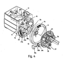
- Figure 4 is an exploded perspective view of the weft feeder of Figure 1, showing the fixing system of Figure 2.
-
- With reference to the figures mentioned above, a generic weft feeder, generally designated by the
reference numeral 10, comprises amotor housing 11 and astationary drum 12, on which a frustum-shaped circularswivel arm 13, keyed on amotor shaft 14 driven by a motor M, winds multiple loops of thread F, which constitute a weft reserve RT. To this purpose,motor shaft 14 is hollow, so that thread F can pass through it; the thread exits through aslot 15 provided at an intermediate section ofshaft 14, and is sent to a guidinghole 16 provided in a peripheral region of the disk that constitutes thearm 13 in order to be wound onto thedrum 12. When requested by the loom (not shown), the loops unwind fromdrum 12 and are fed to the loom, passing through a braking means 17 that controls the mechanical tension of thread F in order to keep it substantially constant. - Since it is necessary to allow the
swivel arm 13 to rotate about the axis H common to drum 12 andmotor shaft 14 between which the arm is interposed, a system is provided for fixing the drum to the motor housing. According to the invention, the fixing system has a set of first permanent magnets, such as 18a, which are detachably received in respective first recessed seats such as 19a, provided with aferromagnetic plate 21a on their bottoms and arranged on a firstannular surface 26 which is concave and frustum-shaped and is formed coaxially at the end ofmotor housing 11. Advantageously, each of theferromagnetic plates 21a is attached by means of a screw 25a to the firstannular surface 26 and is provided with arim 22, forming the edge of the resting surface of the magnet, in order to retain a bushing 23 made of plastic material, which has, for this purpose, a correspondinginside edge 24 at one axial end, shaped to surround the respectivepermanent magnet 18a. Second permanent magnets such as 18b, having opposite polarities, are arranged opposite the first magnets and are also received in respective second seats such as 19b, provided withferromagnetic plates 21b on their bottoms and arranged on a second annular convex frustum-shaped surface 20, which is complementary tosurface 26 and is formed on asupport 27 which is attached to the base ofdrum 12. The second seats are preferably formed ascavities 19b made in the secondannular surface 20; theferromagnetic plates 21b are attached to the bottoms of said cavities by means ofscrews 25b. - Elongated centering brackets such as 35 and centering/attaching brackets such as 36 extend from
support 27, parallelly to axis H, and receivenuts 37 which allowdrum 12 to be connected to support 27 by means ofscrews 38.Swivel arm 13 is keyed to themotor shaft 14 so that itshub 28 is sandwiched between the internal rotating rings ofbearings shoulders Bearings seats motor housing 11 and on the internal cylindrical surface of thesupport 27. -
Neodymium magnets drum 12, withassociated support 27 and thesecond magnets 18b, close to the motor housing, which carries thefirst magnets 18a, a steady connection of the parts is obtained, while a free volume is left between them as required for the passage of the swivel arm and the winding of the thread onto the drum.Ferromagnetic plates respective magnets arm 13 rotates. - In practice, it has been found that the invention fully achieves the intended aim, by providing a weft feeder having a system for securely attaching the drum to the motor housing, which system also allows each individual magnet to be replaced quickly and independently in case of damage or incorrect assembly, while complying with the required alternation of the polarities. Therefore, with the device according to the invention it is possible, if case of break of a magnet, to recover the remaining ones, with obvious cost advantages.
- Another advantage of the device according to the invention is that it has a smaller bulk and a lower weight than known devices, the high magnetic capacity of neodymium being exploited not only for securely attaching the magnets to the respective seats and for achieving a more stable connection between the drum and the motor housing, but also for reducing the number and sizes of said magnets.
- Another advantage of said device is that it has a low manufacturing cost and is simple to manufacture by means of equipment that is common in the field.
Claims (7)
- A weft feeder for textile machines, wherein a swivel arm (13) winds a weft thread (F) onto a stationary drum (12) that is supported coaxially and rotatably on the motor shaft (14) of the swivel arm (13), characterized in that the drum (12) is kept in a fixed angular position by the mutual attraction between a first set of magnets (18a) received in respective first recessed seats (19a) on a first annular surface (26) of the motor housing (11) which is coaxial to the motor shaft (14), and a second set of magnets (18b) received in respective second recessed seats (19b) on a second annular surface of a support (27) at the base of the drum (12), facing the first annular surface (20), each seat (19a, 19b) of both the first and second sets being provided with a ferromagnetic plate (21a, 21b) in its bottom.
- The device of claim 1, characterized in that said first and second annular surfaces (20, 26) are frustum-shaped surfaces.
- The device of claim 2, characterized in that the recessed seats (19a, 19b) of at least one of said sets comprise bushings (23) surrounding the respective ferromagnetic plates (21a) and attached to the respective annular surface (26).
- The device of claim 3, characterized in that each of said ferromagnetic plates (21a) is fixed to the respective annular surface (26) by means of a screw (25a) and has a rim (22), which forms the edge of the resting surface of the magnet and is adapted to engage a corresponding inside edge (24) of said bushing (23) in order to attach it to the respective annular surface.
- The device of anyone of the preceding claims, characterized in that said second seats (19b) are formed in said second annular surface (20) as cavities (19b), the ferromagnetic plate (21b) being detachably attached to the bottom of each of said cavities.
- The device of anyone of the preceding claims, characterized in that elongated centering brackets (35) and centering and fixing brackets (36) protrude from said support (27) parallel to the axis (H) of the drum and accommodate nuts (37) for connecting the drum (12) to the support (27) by means of screws (38).
- The device of anyone of the preceding claims, characterized in that said first and second magnets (18a, 18b) are made of neodymium.
Applications Claiming Priority (2)
| Application Number | Priority Date | Filing Date | Title |
|---|---|---|---|
| ITTO20020029 ITTO20020029U1 (en) | 2002-02-08 | 2002-02-08 | ,, WEFT FEEDER DEVICE FOR TEXTILE MACHINES WITH FIXING SYSTEM OF THE DRUM FIXED TO THE PERFECTED MOTOR BODY ,, |
| ITTO20020029U | 2002-02-08 |
Publications (2)
| Publication Number | Publication Date |
|---|---|
| EP1335055A1 true EP1335055A1 (en) | 2003-08-13 |
| EP1335055B1 EP1335055B1 (en) | 2006-08-16 |
Family
ID=27590484
Family Applications (1)
| Application Number | Title | Priority Date | Filing Date |
|---|---|---|---|
| EP20030001608 Expired - Lifetime EP1335055B1 (en) | 2002-02-08 | 2003-01-24 | Weft feeder for textile machines with improved system for attaching the stationary drum to the motor housing |
Country Status (4)
| Country | Link |
|---|---|
| EP (1) | EP1335055B1 (en) |
| CN (1) | CN100441761C (en) |
| DE (1) | DE60307528T2 (en) |
| IT (1) | ITTO20020029U1 (en) |
Cited By (3)
| Publication number | Priority date | Publication date | Assignee | Title |
|---|---|---|---|---|
| EP1717181A1 (en) * | 2005-04-27 | 2006-11-02 | L.G.L. Electronics S.p.A. | Yarn-braking device in weft feeders for textile machines |
| WO2007048528A1 (en) * | 2005-10-27 | 2007-05-03 | Memminger-Iro Gmbh | Apparatus for fully-automatized control of the length of a yarn |
| EP3591106A1 (en) * | 2018-06-28 | 2020-01-08 | Memminger-IRO GmbH | Thread supply device and method for operating same |
Families Citing this family (2)
| Publication number | Priority date | Publication date | Assignee | Title |
|---|---|---|---|---|
| DE102013113115B4 (en) * | 2013-11-27 | 2016-01-28 | Memminger-Iro Gmbh | Method for controlling the yarn delivery, yarn feeding device and system with yarn feeding devices |
| CN105256447B (en) * | 2015-10-31 | 2017-12-01 | 苏州华哥电器科技有限公司 | A kind of weft accumulator and its storage latitude method |
Citations (4)
| Publication number | Priority date | Publication date | Assignee | Title |
|---|---|---|---|---|
| FR1547158A (en) * | 1966-12-13 | 1968-11-22 | Sulzer Ag | Loom with intermediate weft thread accumulator |
| US4614311A (en) * | 1985-01-30 | 1986-09-30 | Kasuga Denki Co., Ltd. | Yarn storage and delivery apparatus |
| EP0525906A1 (en) * | 1991-07-31 | 1993-02-03 | Rüti-Te Strake B.V. | A device for forming a yarn coil from a yarn supplied from a yarn package |
| EP1059375A1 (en) * | 1999-06-01 | 2000-12-13 | L.G.L. Electronics S.p.A. | Thread braking device for weft feeder, having reduced intervention times |
Family Cites Families (5)
| Publication number | Priority date | Publication date | Assignee | Title |
|---|---|---|---|---|
| CS272202B2 (en) * | 1981-10-13 | 1991-01-15 | Saurer Diederichs Sa | Doser and weft meter for shuttless looms |
| DE3862670D1 (en) * | 1987-04-08 | 1991-06-13 | Sulzer Ag | METHOD FOR THE OPERATION OF A Weft Thread Storage Device For A Weaving Machine. |
| IT1232531B (en) * | 1989-06-29 | 1992-02-19 | Lgl Electronics Spa | WEFT DRUM FEEDER DEVICE FOR FLUID JET WEAVING FRAMES |
| IT1261256B (en) * | 1993-09-10 | 1996-05-09 | Lgl Electronics Spa | SEPARATION DEVICE OF YARN RESERVE COILS FOR WEFT FEEDERS AND WEAVING FRAMES AND SIMILAR |
| CN2292817Y (en) * | 1997-05-07 | 1998-09-30 | 宁波太阳实业总公司 | Magnetic tension yarn storage and feed device |
-
2002
- 2002-02-08 IT ITTO20020029 patent/ITTO20020029U1/en unknown
-
2003
- 2003-01-24 DE DE2003607528 patent/DE60307528T2/en not_active Expired - Lifetime
- 2003-01-24 EP EP20030001608 patent/EP1335055B1/en not_active Expired - Lifetime
- 2003-01-30 CN CNB031034969A patent/CN100441761C/en not_active Expired - Fee Related
Patent Citations (4)
| Publication number | Priority date | Publication date | Assignee | Title |
|---|---|---|---|---|
| FR1547158A (en) * | 1966-12-13 | 1968-11-22 | Sulzer Ag | Loom with intermediate weft thread accumulator |
| US4614311A (en) * | 1985-01-30 | 1986-09-30 | Kasuga Denki Co., Ltd. | Yarn storage and delivery apparatus |
| EP0525906A1 (en) * | 1991-07-31 | 1993-02-03 | Rüti-Te Strake B.V. | A device for forming a yarn coil from a yarn supplied from a yarn package |
| EP1059375A1 (en) * | 1999-06-01 | 2000-12-13 | L.G.L. Electronics S.p.A. | Thread braking device for weft feeder, having reduced intervention times |
Cited By (3)
| Publication number | Priority date | Publication date | Assignee | Title |
|---|---|---|---|---|
| EP1717181A1 (en) * | 2005-04-27 | 2006-11-02 | L.G.L. Electronics S.p.A. | Yarn-braking device in weft feeders for textile machines |
| WO2007048528A1 (en) * | 2005-10-27 | 2007-05-03 | Memminger-Iro Gmbh | Apparatus for fully-automatized control of the length of a yarn |
| EP3591106A1 (en) * | 2018-06-28 | 2020-01-08 | Memminger-IRO GmbH | Thread supply device and method for operating same |
Also Published As
| Publication number | Publication date |
|---|---|
| CN1436884A (en) | 2003-08-20 |
| DE60307528D1 (en) | 2006-09-28 |
| EP1335055B1 (en) | 2006-08-16 |
| ITTO20020029U1 (en) | 2003-08-08 |
| DE60307528T2 (en) | 2007-02-15 |
| ITTO20020029V0 (en) | 2002-02-08 |
| CN100441761C (en) | 2008-12-10 |
Similar Documents
| Publication | Publication Date | Title |
|---|---|---|
| US10100446B2 (en) | Module element for driving and retaining braiding bobbin carriers and a braiding device | |
| KR101064874B1 (en) | Guide roller for wire saw device | |
| EP1335055A1 (en) | Weft feeder for textile machines with improved system for attaching the stationary drum to the motor housing | |
| US9809413B2 (en) | Winding device for strand shaped winding material | |
| US5636748A (en) | Magnetic drum separator | |
| CN111071865B (en) | Coiled material conveying device and adjusting method of conveying device | |
| EP3094586B1 (en) | Spool fixation device with bi-stable magnet assemblies | |
| CN211712305U (en) | Winding device of silk winder | |
| EP1717181B1 (en) | Yarn-braking device in weft feeders for textile machines | |
| CN219010444U (en) | Metal coating device with clamp structure | |
| KR101608741B1 (en) | Lifting apparatus with electromagnet and methode using the same | |
| EP1371594A1 (en) | Weft feeder for weaving machines | |
| CN220875736U (en) | Quick detach mounting panel and casing shaping equipment | |
| CN210956439U (en) | Winding machine | |
| CN223892153U (en) | Wire cylinder frame for weaving wire supply | |
| CN214736511U (en) | Frock is carried to cellosilk for braid over braid | |
| CN210594684U (en) | Doubling winder yarn guide device for textile fabric production | |
| CN220925557U (en) | Rotating wheel type feeding mechanism | |
| CN211687809U (en) | Material receiving and discharging mechanism | |
| CN208345471U (en) | A kind of stable take-up | |
| KR20160003653U (en) | magnet gear | |
| CN221190656U (en) | Roller and winding equipment | |
| CN112975425B (en) | Peeling and grinding device for aluminum alloy cast rod | |
| CN214831481U (en) | High-speed rope machine reel frame | |
| CN101443498A (en) | Improved yarn unwinding device |
Legal Events
| Date | Code | Title | Description |
|---|---|---|---|
| PUAI | Public reference made under article 153(3) epc to a published international application that has entered the european phase |
Free format text: ORIGINAL CODE: 0009012 |
|
| AK | Designated contracting states |
Designated state(s): AT BE BG CH CY CZ DE DK EE ES FI FR GB GR HU IE IT LI LU MC NL PT SE SI SK TR |
|
| AX | Request for extension of the european patent |
Extension state: AL LT LV MK RO |
|
| 17P | Request for examination filed |
Effective date: 20030725 |
|
| AKX | Designation fees paid |
Designated state(s): BE CH DE IT LI SE |
|
| GRAP | Despatch of communication of intention to grant a patent |
Free format text: ORIGINAL CODE: EPIDOSNIGR1 |
|
| GRAS | Grant fee paid |
Free format text: ORIGINAL CODE: EPIDOSNIGR3 |
|
| GRAA | (expected) grant |
Free format text: ORIGINAL CODE: 0009210 |
|
| AK | Designated contracting states |
Kind code of ref document: B1 Designated state(s): BE CH DE IT LI SE |
|
| PG25 | Lapsed in a contracting state [announced via postgrant information from national office to epo] |
Ref country code: IT Free format text: LAPSE BECAUSE OF FAILURE TO SUBMIT A TRANSLATION OF THE DESCRIPTION OR TO PAY THE FEE WITHIN THE PRESCRIBED TIME-LIMIT;WARNING: LAPSES OF ITALIAN PATENTS WITH EFFECTIVE DATE BEFORE 2007 MAY HAVE OCCURRED AT ANY TIME BEFORE 2007. THE CORRECT EFFECTIVE DATE MAY BE DIFFERENT FROM THE ONE RECORDED. Effective date: 20060816 |
|
| REG | Reference to a national code |
Ref country code: CH Ref legal event code: EP |
|
| REF | Corresponds to: |
Ref document number: 60307528 Country of ref document: DE Date of ref document: 20060928 Kind code of ref document: P |
|
| REG | Reference to a national code |
Ref country code: CH Ref legal event code: NV Representative=s name: PA ALDO ROEMPLER |
|
| REG | Reference to a national code |
Ref country code: SE Ref legal event code: TRGR |
|
| PLBE | No opposition filed within time limit |
Free format text: ORIGINAL CODE: 0009261 |
|
| STAA | Information on the status of an ep patent application or granted ep patent |
Free format text: STATUS: NO OPPOSITION FILED WITHIN TIME LIMIT |
|
| 26N | No opposition filed |
Effective date: 20070518 |
|
| REG | Reference to a national code |
Ref country code: CH Ref legal event code: PCAR Free format text: ALDO ROEMPLER PATENTANWALT;BRENDENWEG 11 POSTFACH 154;9424 RHEINECK (CH) |
|
| PGFP | Annual fee paid to national office [announced via postgrant information from national office to epo] |
Ref country code: CH Payment date: 20090417 Year of fee payment: 7 |
|
| REG | Reference to a national code |
Ref country code: CH Ref legal event code: PL |
|
| PG25 | Lapsed in a contracting state [announced via postgrant information from national office to epo] |
Ref country code: LI Free format text: LAPSE BECAUSE OF NON-PAYMENT OF DUE FEES Effective date: 20100131 Ref country code: CH Free format text: LAPSE BECAUSE OF NON-PAYMENT OF DUE FEES Effective date: 20100131 |
|
| PGFP | Annual fee paid to national office [announced via postgrant information from national office to epo] |
Ref country code: SE Payment date: 20190124 Year of fee payment: 17 |
|
| PGFP | Annual fee paid to national office [announced via postgrant information from national office to epo] |
Ref country code: BE Payment date: 20200122 Year of fee payment: 18 |
|
| REG | Reference to a national code |
Ref country code: SE Ref legal event code: EUG |
|
| REG | Reference to a national code |
Ref country code: SE Ref legal event code: EUG |
|
| PG25 | Lapsed in a contracting state [announced via postgrant information from national office to epo] |
Ref country code: SE Free format text: LAPSE BECAUSE OF NON-PAYMENT OF DUE FEES Effective date: 20200125 |
|
| PGFP | Annual fee paid to national office [announced via postgrant information from national office to epo] |
Ref country code: IT Payment date: 20210105 Year of fee payment: 19 |
|
| PGFP | Annual fee paid to national office [announced via postgrant information from national office to epo] |
Ref country code: DE Payment date: 20210128 Year of fee payment: 19 |
|
| REG | Reference to a national code |
Ref country code: BE Ref legal event code: MM Effective date: 20210131 |
|
| PG25 | Lapsed in a contracting state [announced via postgrant information from national office to epo] |
Ref country code: BE Free format text: LAPSE BECAUSE OF NON-PAYMENT OF DUE FEES Effective date: 20210131 |
|
| REG | Reference to a national code |
Ref country code: DE Ref legal event code: R119 Ref document number: 60307528 Country of ref document: DE |
|
| PG25 | Lapsed in a contracting state [announced via postgrant information from national office to epo] |
Ref country code: DE Free format text: LAPSE BECAUSE OF NON-PAYMENT OF DUE FEES Effective date: 20220802 |
|
| PG25 | Lapsed in a contracting state [announced via postgrant information from national office to epo] |
Ref country code: IT Free format text: LAPSE BECAUSE OF NON-PAYMENT OF DUE FEES Effective date: 20220124 |