EP1334908A1 - Apparatus and method for filling bulk materials - Google Patents
Apparatus and method for filling bulk materials Download PDFInfo
- Publication number
- EP1334908A1 EP1334908A1 EP03405066A EP03405066A EP1334908A1 EP 1334908 A1 EP1334908 A1 EP 1334908A1 EP 03405066 A EP03405066 A EP 03405066A EP 03405066 A EP03405066 A EP 03405066A EP 1334908 A1 EP1334908 A1 EP 1334908A1
- Authority
- EP
- European Patent Office
- Prior art keywords
- filling
- container
- filling head
- bag
- residual
- Prior art date
- Legal status (The legal status is an assumption and is not a legal conclusion. Google has not performed a legal analysis and makes no representation as to the accuracy of the status listed.)
- Withdrawn
Links
Images


Classifications
-
- B—PERFORMING OPERATIONS; TRANSPORTING
- B65—CONVEYING; PACKING; STORING; HANDLING THIN OR FILAMENTARY MATERIAL
- B65B—MACHINES, APPARATUS OR DEVICES FOR, OR METHODS OF, PACKAGING ARTICLES OR MATERIALS; UNPACKING
- B65B1/00—Packaging fluent solid material, e.g. powders, granular or loose fibrous material, loose masses of small articles, in individual containers or receptacles, e.g. bags, sacks, boxes, cartons, cans, or jars
- B65B1/28—Controlling escape of air or dust from containers or receptacles during filling
Definitions
- the invention relates to a filling device and a method for filling of bulk goods in bags open on one side, drums with inner bags, or so-called big bags.
- a well-known alternative is the endless hose system Advantages compared to filling systems used so far, that here also low dust the container can be changed.
- the disadvantage of this system lies in the low absorption capacity of the so-called endless bag of approx. 30 m at ⁇ 100 ⁇ m (micrometers), whereby the low material thickness, if a container is filled with> 25 kg net, cause a problem can.
- the sack can easily be lifted out of the drum tear.
- the endless bag can be closed by means of clips or welding take place, here also only thin bag material ⁇ 100 microns Advantage is. Low temperatures can be used for welding or when clinging, the end becomes denser because the thinner material thicker material should be used to compress it better slightly leaky floor closures can be expected.
- a bottling plant essentially consists of a feed hopper, one Dosing device and the so-called filling head.
- a dosing device Swivel slide, squeeze hoses or screw conveyors, as a filling head become simple open pipes or tapered, conical, open Cylinder (truncated cone) used. Sealing from the filling head to one side open sack (big bag) is usually made with inflatable cuffs without Ring (advantage: very tight on the outside, material is stretched.
- shut-off device e.g. a flap at the end of the filling head install?
- a normal shut-off device valve, flap or slide at the open end of the filling head prevents falling of Product from the filling pipe, since this shut-off device also comes with the product If the container is contaminated, the product also falls from it when the container is changed downward.
- the object of the present invention is a method and an associated To provide a device to ensure that when changing containers no product is released into the environment.
- the invention accordingly relates to a device for low-dust Change of containers of one-sided open sacks and big bags with dusty ones or granular bulk material, which is characterized in that in the filling head Means are provided to one after filling a container Filling head to grasp remaining container hose ("residual container") and to be withdrawn through the outlet opening of the filling head.
- the inventive The device has the advantage that when changing the container Danger of environmental pollution in comparison with known devices is less.
- an empty container can already be under be arranged on both sides of the remaining container before this through the outlet opening of the filling head is pulled upwards.
- the Gripping means can for example be a movable gripping tool, e.g.
- a movable gripping pliers or gripping arm with which the remaining container packed and up through the exit opening, i.e. opposite the direction of the filling stream can be removed. It is conceivable that the filling head via a line with shut-off device in connection with a Vacuum source is. This has the advantage that a suction effect in the Filling head is adjustable when the remaining bag is removed.
- the gripping means are advantageously one that ends in the filling head or in the filling tube or additional pipe connected to the filling head, below also called “residual bag suction pipe", which with a vacuum source in Connection is established.
- the additional suction tube makes it possible for a after closing and separating the filled container at the filling head remaining container hose, hereinafter also referred to as “residual container”, sucked in and out through the suction pipe connected to the filling head can be.
- the remaining container can be sucked off particularly easily, if this closes to form a residual bag when the container is removed becomes. It is conceivable that the suction pipe is connected directly to the filling pipe is and that the residual bag is withdrawn through the filling tube becomes.
- the filling head jammed sack (inliner, big bag) by means of a closing device with clips, cable ties, bag closers or the like twice, i.e. by means of two clamping points provided at a distance from one another, locked.
- the filling container can then between the closures be separated (cut through).
- the remaining bag remains on the filling head back. Thanks to the remaining bag, the filling head remains even after removal of the filled container closed to the outside. Even if the clasp of the remaining bag should not be carried out exactly, can be put on no product can get into the environment due to negative pressure on the filling head, because the direction of flow to the exhaust fan (vacuum generator) of a dedusting system acts.
- two pinch points can also be a single pinch point wide set come.
- the residual bag suction pipe by means of a shut-off device is lockable. This has the advantage that no bulk goods are filled in the suction pipe can get.
- the suction pipe can also be used permanently be subjected to a negative pressure. This expediently extends Residual bag suction tube into the filling head. This allows the remaining bag easily grasped and vacuumed. If the residual bag suction tube is movable and movable a certain distance in the direction of the outlet opening the remaining bag can be particularly easily gripped.
- the end of the Residual bag suction tube as a closing flap or valve flap for the outlet opening of the filling head.
- the suction pipe can be rigid and provided with a shut-off device be attached to the filling head.
- the suction tube is preferably movable in the Filling head continued as a shut-off device with a hollow shaft, which is the outlet opening of the filling head closes to the outside when changing the container.
- the present invention also relates to a method for filling of dusty or granular bulk material, which characterizes it is that the remaining container on the filling head through the outlet opening is subtracted.
- This method has the advantage that the Can change faster and the risk of contamination the environment is less.
- the container is by means of a wide weld seam or two spaced apart and the clamping points running transversely to the bag opening are closed such that after the filled container has been cut off, the filling head closing residual bag remains.
- the remaining bag can then through the Outlet opening by means of a vacuum and / or movable gripping means subtracted from.
- the container is expediently equipped with at least 2 bag closers, Cable ties or clips to form two clamping points.
- two disconnection points single wide pinch point, e.g. by welding, manufacturing and cut them in about the middle so that a closed, filled container on the filling head and a container that closes the outlet opening The remaining bag remains.
- the filling head with a connected, closed container is advantageous a preferably light one even before the filled container is separated Vacuum applied. This has the advantage that no dust particles from the Filling head can escape to the environment, as this due to the negative pressure be sucked towards the vacuum source.
- the residual bag is preferably drawn off into a dedusting system. There or in front of the dedusting system, a device for separation can be used of the residual bag may be provided.
- Figures 1 to 5 show the prior art mainly used bag clamps 19 for releasably attaching a one-sided open container 13, e.g. of a sack to a filling head 11.
- Figure 1 shows a filling head 11 with an inflatable sleeve 15, but without a ring.
- This Embodiment of a sealing device has the advantage that it is very dense to the outside. Disadvantages, however, are that the filling head 11 is very voluminous and tailored to a specific sack diameter is. Another disadvantage is that the sack material tears when inflated can. If sacks with different sack diameters are to be filled, so there must be a large stock of replacement parts.
- the known sealing device according to Figure 2 has an inflatable sleeve 15 with a ring 17.
- sealing is also used Ring or funnel clamping devices 16 ( Figure 3) used.
- Ring or funnel clamping devices 16 Figure 3
- With these Embodiments is the container to be filled (sack) by means of a Ring 18 clamped from the outside to the funnel jacket.
- One is also known Sealing device with a bag buckle arranged on a belt 22 20 ( Figure 4). To attach a container to the filling head 11 the straps 22 around the filling head and the container placed over the filling head placed and closed with the bag buckle 20.
- FIG. 5 shows another filling head with a vacuum or inflation sleeve 21.
- This Embodiment has the advantage that the seal is carried out internally is.
- the filling head can be made less voluminous.
- the filling heads are also for different bag diameters are suitable.
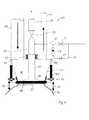
- the filling device 23 shown in FIGS. 6 to 10 has a through a hopper 25 formed filling head 11, on which a sack (bundle) 13th is attached.
- a Bag clamping device 19 e.g. an inflatable gasket pressed in from the outside, provided, which will be described in more detail below.
- an exhaust pipe 27 is provided in the funnel 25.
- the suction pipe 27 is with a pipe 29 connected, which with a vacuum source not shown in the figures, e.g. with a fan with exhaust air filter.
- a Shut-off device 31, e.g. a valve allows the suction pipe 27 opposite to seal the vacuum source airtight.
- the suction pipe 27 is axially displaceable relative to the pipe 29 arranged.
- a sliding tube or bellows 33 provided which connects the suction pipe 27 to the pipe 29. through a motor, hydraulic or pneumatic device, not shown the suction pipe 27 is adjustable in height. In the lowered state ( Figure 6) is the end of the suction tube 27 in the area of Outlet opening of the funnel 25.
- the suction pipe is 27 widened to a closure flap 35.
- the closure flap 35 has one Diameter which corresponds approximately to the outlet opening 37 of the funnel 25 and closes the filling head to the outside.
- a filling pipe 39 also opens into the funnel 25.
- the filling pipe 39 is connected via a Shut-off device with a storage container (neither in the figures shown) for a powdery or granular bulk material in connection.
- a storage container not in the figures shown
- the Filling tube 39 can be integrated known metering devices to the Dosing the amount of bulk material to be filled.
- a second opens Tube 41 in the funnel 25.
- the tube 41 serves as a gas suspension line and is connected to a filter system and / or the filling bunker. about the gas suspension line 41 becomes present in the atmosphere of the filling head Product returned to the filling bunker during the filling process.
- a vacuum source can be connected to the filter system.
- the gas suspension line 41 can also be used as a residual bag suction pipe 27 become.
- a line 45 is seen in the flow direction in front of the shut-off device 31 connected to the suction pipe 27. By means of a valve 47 can the line 45 are blocked.
- a bypass line 49 is before and after the valve 47 connected to the line 45. In the bypass line 49 is a valve 51 and a small flow meter 53 are provided.
- the lines 45 and 49 serve either the suction tube 27 during filling flush with a small gas stream or a new container 13 via line 39 inflate using a stronger gas flow.
- the bag clamping device 19 shown only schematically has one or several lifting cylinders 55, which have one end at the suspension points Support 57 on the filling device 23. The other end of the Lift cylinder engages the clamping ring 18.
- the lifting cylinders are in the axial direction (Arrow 61) adjustable in length.
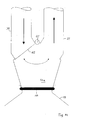
- Figures 7 to 10 show the individual steps in the filling of a Container 13 in detail.
- Figure 8 it can be seen that when closing the Container 13 has two clamps arranged a short distance apart 62a, 62b or container closures. The first pinch point 62a closes the container 13, the second clamping point 62b seals the container hose remaining on the filling head to the so-called Residual bag 63.
- a residual bag holding device can optionally be attached to the bag clamping device 19 64 may be provided.
- the remaining bag holding device 64 can be the remaining bag 63 clamp on the filling head 11, even if the clamping ring 18 already is solved.
- the second embodiment of a filling device has a filling head 11a, in which a filling pipe 39 and a suction pipe 27 lead.
- a movable, preferably provided in the filling head 11a pivotable flap 65 pivotable about a pivot axis 67. It is in the one end position, the filling pipe 39 (Fig. 11), and in the other end position the suction pipe 27 closed.
- the seal to the sack that is open on one side 13 and the change of containers can take place as shown in FIG. 6.
- the container 13 is prepared.
- the sack 13 or also the big bag is connected to the filling head 11 preferably by means of ring or funnel clamping or blah ring (FIG. 6).
- the container 13 consists of a gas-impermeable, flexible material.
- the container 13 is first evacuated as best as possible.
- the atmosphere is sucked off through the residual bag suction pipe 29 (FIG. 6) with the shut-off element 31 open to a filter system (dust removal).
- the shut-off device 31 is closed and then the container 13 is preferably inflated with an inerting gas (nitrogen, CO 2 , noble gas).
- the valve 47 remains open until the container 13 is filled with gas.
- the system is switched to rinsing.
- the valve 51 is opened and a small amount of air or inert gas flows continuously via the small flow meter 53 via the residual bag suction pipe 27 into the filling head 11.
- the lower part of the residual bag suction pipe 27 is also lifted by means of a lifting cylinder 55.
- the dosage from the filling bunker into the filling container 13 can, respectively, via the filling chute.
- Filling tube can be carried out with all known methods (squeeze tube, screw or swivel slide). It is advantageous if a gas oscillation is carried out via pipe 41 between the filling bunker and the filling container. However, this is not absolutely necessary, but prevents product losses in the direction of dedusting and thus reduces maintenance costs.
- the container 13 is closed with cable ties, bag closers or clamps at two spaced apart locations 62a, 62b in order to form two clamping locations 62a, 62b.
- the two pinch points 62a, 62b can also be two narrow weld seams or a single wide weld seam.
- the shut-off device 51 ininert gas flushing
- the container is prepared and the bag 13 is placed on the filling head (preferably Ring or funnel clamping) connected.
- the dosage of the Bulk material is now removed from the storage bunker with a not shown known metering device via filling pipe 39 into the filling container 13th
- the container 13 is fastened with cable ties, Bag closers, clamps twice to form two spaced apart arranged terminal points closed. Alternatively, you could a wide weld seam should be provided.
- the shut-off device 31 opens to the residual bag suction pipe 27 and at the same time closes the filling pipe 39. Now there is a slight negative pressure (vacuum) between the filling head 11a and the container 13 created so that the upper part of the bag (residual bag 63) is sucked in becomes.
- an additional residual bag holder 64 (see Figure 6) are activated, which holds the remaining bag on the filling head. Is the Residual bag holder 64 activated, the maximum generated by a blower Vacuum can be applied immediately.
- the sack 13 is cut through (separated).
- the full package 13 is now removed from the scales, a new container 13 is lowered the clamping ring 18 by means of lifting cylinder 55 and threading a new one Sacks prepared and put on hold, that is, immediately is now under the filling head 11a with the remaining bag 63 held an empty sack 13.
- the vacuum is via the residual sack suction tube 27 increased (the vacuum gets better), and the remaining bag 63 is over the Residual bag suction tube 27 e.g. sucked into a filter system or separation chamber.
- the blower output is now reduced again, to recirculation changed over, and the fresh container 13 finished to the filling head 11a connected.
- the device according to the invention thus ensures that when changing containers in a filling system with dusty or granular Bulk goods, such as fine chemicals or active substances that are low in dust he follows. This will contaminate the system, the filling container and pallets avoided, thereby cleaning them eliminated. In addition, contamination of the filling team or prevents possible cross-contamination with other chemicals.
- the filling head remains closed to the outside, since according to FIG. 6 the closure cap 35 of the residual bag suction tube 27 closes the filling head 11 or additionally as in FIG. 6, the residual bag 62a, 62b remains on the filling head until a new filling is started and the system is rendered inert remains. Adhesive product in the filling head does not have any external environmental influences exposed.
Landscapes
- Engineering & Computer Science (AREA)
- Mechanical Engineering (AREA)
- Basic Packing Technique (AREA)
Abstract
Description
Die Erfindung betrifft eine Abfüllvorrichtung und ein Verfahren zum Abfüllen von Schüttgütern in einseitig offene Säcke, Trommeln mit Innensäcken, oder sogenannte Big Bags.The invention relates to a filling device and a method for filling of bulk goods in bags open on one side, drums with inner bags, or so-called big bags.
Bei der Befüllung von Kunststoffsäcken mit staubförmigen oder körnigen Schüttgütern kommt es im Füllkopf zur Anhaftung von Staubteilchen (Produkt). Wenn nach der Befüllung der Sack entfernt wird, ist der Füllkopf nach außen offen und das anhaftende Produkt fällt auf die darunter liegende Waage ( Nachteile → Kreuzkontamination, Reinraumverschmutzung, Luft und Wassergefährdung, erhöhter Schutz beim Abfüllen für das Personal nötig, Materialkorrosion, Wiegefehler durch Verschmutzung, erschwerte Einhaltung der GMP Vorschriften)When filling plastic bags with dusty or granular ones Bulk goods get dust particles attached to the filling head (Product). When the sack is removed after filling, the filling head is open to the outside and the adhering product falls on the one below Libra (disadvantages → cross contamination, clean room pollution, air and Water hazard, increased protection for the filling necessary for the staff, Material corrosion, weighing errors due to contamination, difficult compliance GMP regulations)
Eine bekannte Alternative ist das Endlosschlauchsystem, hier liegen die Vorteile zu bisher verwendeten Abfüllanlagen, dass hier ebenfalls staubarm der Gebindewechsel durchgeführt werden kann. Der Nachteil dieses Systems liegt in der geringen Aufnahmekapazität des sogenannten Endlossackes von ca. 30 m bei < 100 µm (Mikrometer), wobei hier die geringe Materialstärke, wenn ein Gebinde mit > 25 kg Netto befüllt wird, ein Problem hervorrufen kann. Der Sack kann beim Herausheben aus der Trommel jedoch sehr leicht zerreißen.A well-known alternative is the endless hose system Advantages compared to filling systems used so far, that here also low dust the container can be changed. The disadvantage of this system lies in the low absorption capacity of the so-called endless bag of approx. 30 m at <100 µm (micrometers), whereby the low material thickness, if a container is filled with> 25 kg net, cause a problem can. However, the sack can easily be lifted out of the drum tear.
Das Verschließen des Endlossackes kann mittels Klammern oder Verschweißen erfolgen, wobei hier ebenfalls nur dünnes Sackmaterial < 100 µm von Vorteil ist. Beim Schweißen kann mit niederen Temperaturen gearbeitet werden bzw. beim Klammern wird der Abschluss dichter, da das dünnere Material besser zusammengepresst werden kann, sollte dickeres Material zum Einsatz kommen, so ist mit leicht undichten Bodenverschlüssen zu rechnen.The endless bag can be closed by means of clips or welding take place, here also only thin bag material <100 microns Advantage is. Low temperatures can be used for welding or when clinging, the end becomes denser because the thinner material thicker material should be used to compress it better slightly leaky floor closures can be expected.
Ein Problem beim Schweißen ist auch noch, das eine relativ saubere Sackinnenfläche benötigt wird, da sonst die Schweißnaht nicht sauber ausgeführt wird und diese aufgehen kann.Another problem with welding is that the inner surface of the bag is relatively clean is required, otherwise the weld seam will not be properly executed and it can open.
Eine Abfüllanlage besteht im Wesentlichen aus einem Vorlagebunker, einer Dosiereinrichtung und dem sogenannten Füllkopf. Als Dosiereinrichtung werden Schwenkschieber, Quetschschläuche oder Förderschnecken, als Füllkopf werden einfache offene Rohre oder nach unten verjüngte, konische, offene Zylinder (Kegelstumpf) verwendet. Die Abdichtung vom Füllkopf zum einseitig offenen Sack (Big-Bag) wird üblicherweise mit Blähmanschetten ohne Ring (Vorteil: nach außen sehr dicht, Material wird gespannt. Nachteil: sehr großer Füllkopf, unflexibel auf unterschiedliche Sackdurchmesser, Sackm a-terial kann beim Aufblasen zerreißen, hohe Ersatzteilhaltung für unterschiedliche Sackdurchmesser), bzw. Blähmanschetten mit Ring, Ring oder Trichterklemmung, einer Sackschnalle oder Vakuum bzw. Blähmanschette innenwirkend durchgeführt (Vorteil: kleinerer Füllkopf möglich, flexibel auf unterschiedliche Sackdurchmesser )A bottling plant essentially consists of a feed hopper, one Dosing device and the so-called filling head. As a dosing device Swivel slide, squeeze hoses or screw conveyors, as a filling head become simple open pipes or tapered, conical, open Cylinder (truncated cone) used. Sealing from the filling head to one side open sack (big bag) is usually made with inflatable cuffs without Ring (advantage: very tight on the outside, material is stretched. Disadvantage: very large filling head, inflexible to different sack diameters, sack material can tear when inflated, high spare parts inventory for different Bag diameter), or inflatable sleeves with ring, ring or Funnel clamping, a bag buckle or vacuum or inflatable sleeve performed internally (advantage: smaller filling head possible, flexible on different bag diameters)
Wie sieht es aus, wenn man ein Absperrorgan z.B. eine Klappe am Füllkopfende anbringt? Ein normales Absperrorgan (Ventil, Klappe oder Schi e-ber) am offenen Ende des Füllkopfes verhindert zwar das Nachfallen von Produkt aus dem Füllrohr, da dieses Absperrorgan aber ebenfalls mit Produkt kontaminiert wird, fällt auch von diesem das Produkt beim Gebindewechsel nach unten.What does it look like if you have a shut-off device e.g. a flap at the end of the filling head install? A normal shut-off device (valve, flap or slide) at the open end of the filling head prevents falling of Product from the filling pipe, since this shut-off device also comes with the product If the container is contaminated, the product also falls from it when the container is changed downward.
Alle bisher bekannten Vorrichtungen (Ausnahme: Endlossacksystem während des Betriebs; beim Kartuschenwechsel treten jedoch dieselben Probleme auf) gewährleisten erfahrungsgemäß keinen ausreichenden Schutz vor dem Nachfallen von Produkt aus dem Füllkopf (Füllrohr).All previously known devices (exception: endless bag system during operation; However, the same problems occur when changing the cartridge experience has shown that adequate protection against the Falling product from the filling head (filling pipe).
Aufgabe der vorliegenden Erfindung ist es, ein Verfahren und eine dazu gehörende Vorrichtung bereitzustellen, die gewährleisten, dass beim Gebindewechsel kein Produkt in die Umwelt gelangt.The object of the present invention is a method and an associated To provide a device to ensure that when changing containers no product is released into the environment.
Gegenstand der Erfindung ist demnach eine Vorrichtung zum staubarmen Gebindewechsel von einseitig offenen Säcken und Big-Bags mit staubförmigen oder körnigem Schüttgut, die dadurch gekennzeichnet ist, dass im Füllkopf Mittel vorgesehen sind, um einen nach dem Befüllen eines Gebindes am Füllkopf verbleibenden Restgebindeschlauch ("Restgebinde") zu greifen und durch die Austrittsöffnung des Füllkopfes hindurch abzuziehen. Die erfindungsgemässe Vorrichtung hat den Vorteil, dass beim Gebindewechsel die Gefahr einer Verschmutzung der Umgebung im Vergleich mit bekannten Vorrichtungen geringer ist. Insbesondere kann ein leeres Gebinde bereits unter dem beidseitig offenen Restgebinde angeordnet sein, bevor diesesr durch die Austrittsöffnung des Füllkopfes hindurch nach oben abgezogen wird. Die Greifmittel können beispielsweise ein bewegliches Greifwerkzeug, z.B. eine bewegliche Greifzange oder Greifarm, sein, mit welchem das Restgebinde gepackt und durch die Austrittsöffnung hindurch nach oben, d.h. entgegen der Richtung des Abfüllstromes, entfernt werden kann. Es ist denkbar, dass der Füllkopf über eine Leitung mit Absperreinrichtung in Verbindung mit einer Unterdruckquelle ist. Dies hat den Vorteil, dass eine Sogwirkung in den Füllkopf hinein einstellbar ist, wenn der Restsack entfernt wird.The invention accordingly relates to a device for low-dust Change of containers of one-sided open sacks and big bags with dusty ones or granular bulk material, which is characterized in that in the filling head Means are provided to one after filling a container Filling head to grasp remaining container hose ("residual container") and to be withdrawn through the outlet opening of the filling head. The inventive The device has the advantage that when changing the container Danger of environmental pollution in comparison with known devices is less. In particular, an empty container can already be under be arranged on both sides of the remaining container before this through the outlet opening of the filling head is pulled upwards. The Gripping means can for example be a movable gripping tool, e.g. a movable gripping pliers or gripping arm, with which the remaining container packed and up through the exit opening, i.e. opposite the direction of the filling stream can be removed. It is conceivable that the filling head via a line with shut-off device in connection with a Vacuum source is. This has the advantage that a suction effect in the Filling head is adjustable when the remaining bag is removed.
Vorteilhaft sind die Greifmittel ein in den Füllkopf oder in das Füllrohr mü n-dendes oder am Füllkopf angeschlossenes, zusätzliches Rohr, nachfolgend auch "Restsackabsaugrohr" genannt, welches mit einer Unterdruckquelle in Verbindung steht. Durch das zusätzliche Absaugrohr ist es möglich, dass ein nach dem Verschließen und Abtrennen des gefüllten Gebindes am Füllkopf zurückbleibender Gebindeschlauch, nachfolgend auch "Restgebinde" genannt, durch das an den Füllkopf angeschlossene Absaugrohr an- und abgesaugt werden kann. Besonders leicht kann das Restgebinde abgesaugt werden, wenn dieses beim Abtrennen des Gebindes zu einem Restsack verschlossen wird. Denkbar ist, dass das Absaugrohr direkt an das Füllrohr angeschlossen ist und dass entsprechend der Restsack durch das Füllrohr abgezogen wird.The gripping means are advantageously one that ends in the filling head or in the filling tube or additional pipe connected to the filling head, below also called "residual bag suction pipe", which with a vacuum source in Connection is established. The additional suction tube makes it possible for a after closing and separating the filled container at the filling head remaining container hose, hereinafter also referred to as "residual container", sucked in and out through the suction pipe connected to the filling head can be. The remaining container can be sucked off particularly easily, if this closes to form a residual bag when the container is removed becomes. It is conceivable that the suction pipe is connected directly to the filling pipe is and that the residual bag is withdrawn through the filling tube becomes.
Bei der erfindungsgemäßen Vorrichtung wird nach dem Befüllen der am Füllkopf eingeklemmte Sack (Inliner, Big Bag) mittels einer Verschliesseinrichtung mit Klammern, Kabelbindern, Sackschließern oder dergleichen zweifach, d.h. mittels zwei in Abstand voneinander vorgesehenen Abklemmstellen, verschlossen. Das Abfüllgebinde kann sodann zwischen den Verschlüssen getrennt (durchgeschnitten) werden. Am Füllkopf bleibt der Restsack zurück. Durch den Restsack bleibt der Füllkopf auch nach der Entfernung des gefüllten Gebindes nach außen verschlossen. Selbst wenn der Verschluss des Restsackes nicht exakt ausgeführt sein sollte, kann durch Anlegen eines Unterdrucks an den Füllkopf kein Produkt in die Umwelt gelangen, da die Flussrichtung zum Absauggebläse (Unterdruckerzeuger) einer Entstaubungsanlage wirkt. Über das Restsackabsaugrohr kann dann am Abfüllkopf ein leichter Unterdruck angelegt werden, wobei der obere (vom vollen Gebinde abgebundene Sackteil = Restsack) angesaugt wird. Anstelle von zwei Abklemmstellen kann auch eine einzige breite Abklemmstelle zum Ei n-satz kommen. Als breite Abklemmstelle soll ein Verschluss, z.B. Schweissstelle, einer solchen Breite verstanden sein, der ermöglicht, das Gebinde in ein verschlossenes, gefülltes Gebinde und einen Restsack mit einer Restsacköffnung zu trennen. In the device according to the invention, after filling, the filling head jammed sack (inliner, big bag) by means of a closing device with clips, cable ties, bag closers or the like twice, i.e. by means of two clamping points provided at a distance from one another, locked. The filling container can then between the closures be separated (cut through). The remaining bag remains on the filling head back. Thanks to the remaining bag, the filling head remains even after removal of the filled container closed to the outside. Even if the clasp of the remaining bag should not be carried out exactly, can be put on no product can get into the environment due to negative pressure on the filling head, because the direction of flow to the exhaust fan (vacuum generator) of a dedusting system acts. The remaining bag suction tube can then be attached to the filling head a slight negative pressure should be applied, the upper one (from full Bundled bag part = residual bag) is sucked in. Instead of two pinch points can also be a single pinch point wide set come. A lock, e.g. Weld, of such a width that allows the container in a closed, filled container and a residual bag with a residual bag opening to separate.
Das volle Gebinde wird vom Waagentisch genommen und ein frisches Gebinde vorbereitet und in Warteposition gebracht. Dieses Gebinde ist nun genau unterhalb des angesaugten Restsackes. Dieser Restsack wird nun über das Restsack-Absaugrohr vorzugsweise in eine Entstaubungsanlage abgesaugt. Da das frische Gebinde unter dem Restsack vorbereitet ist und eine Gasströmung in Richtung zum Entstaubungsgebläse wirkt, kann kein Staub (Produkt) auf den Waagentisch gelangen.The full container is removed from the weighing table and a fresh container prepared and put on hold. This package is now accurate below the sucked in residual bag. This remaining bag is now over the Residual bag suction pipe preferably suctioned off in a dedusting system. Since the fresh container is prepared under the remaining bag and one Gas flow acts towards the dedusting fan, no dust can (Product) reach the weighing table.
Vorteilhaft ist, wenn das Restsackabsaugrohr mittels eines Absperrorgans verschließbar ist. Dies hat den Vorteil, dass beim Befüllen kein Schüttgut in das Absaugrohr gelangen kann. Auch kann das Absaugrohr permanent mit einem Unterdruck beaufschlagt sein. Zweckmäßigerweise erstreckt sich das Restsackabsaugrohr in den Füllkopf hinein. Dadurch kann der Restsack leicht gefasst und abgesaugt werden. Wenn das Restsackabsaugrohr beweglich und eine bestimmte Strecke in Richtung zur Austrittsöffnung bewegbar ist, kann der Restsack besonders leicht gefasst werden.It is advantageous if the residual bag suction pipe by means of a shut-off device is lockable. This has the advantage that no bulk goods are filled in the suction pipe can get. The suction pipe can also be used permanently be subjected to a negative pressure. This expediently extends Residual bag suction tube into the filling head. This allows the remaining bag easily grasped and vacuumed. If the residual bag suction tube is movable and movable a certain distance in the direction of the outlet opening the remaining bag can be particularly easily gripped.
Gemäß einer besonders bevorzugten Ausführungsform ist das Ende des Restsackabsaugrohrs als Verschlussklappe oder Ventilklappe für die Austrittsöffnung des Füllkopfes ausgebildet. Dies hat den Vorteil, dass kein Schüttgut aus dem Füllkopf fallen kann.According to a particularly preferred embodiment, the end of the Residual bag suction tube as a closing flap or valve flap for the outlet opening of the filling head. This has the advantage that none Bulk can fall out of the filling head.
Das Absaugrohr kann starr ausgeführt und mit einem Absperrorgan versehen am Füllkopf angebracht sein. Vorzugsweise ist das Absaugrohr beweglich im Füllkopf als Absperrorgan mit Hohlwelle weitergeführt, welches die Austrittsöffnung des Füllkopfs beim Gebindewechsel nach außen verschließt.The suction pipe can be rigid and provided with a shut-off device be attached to the filling head. The suction tube is preferably movable in the Filling head continued as a shut-off device with a hollow shaft, which is the outlet opening of the filling head closes to the outside when changing the container.
Gegenstand der vorliegenden Erfindung ist auch ein Verfahren zum Abfüllen von staubförmigem oder körnigem Schüttgut, welches dadurch charakterisiert ist, dass das am Füllkopf verbleibende Restgebinde durch die Austrittsöffnung abgezogen wird. Dieses Verfahren hat den Vorteil, dass der Gebindewechsel schneller vonstatten gehen kann und die Kontaminationsgefahr der Umgebung geringer ist.The present invention also relates to a method for filling of dusty or granular bulk material, which characterizes it is that the remaining container on the filling head through the outlet opening is subtracted. This method has the advantage that the Can change faster and the risk of contamination the environment is less.
Gemäss einer besonders bevorzugten Verfahrensvariante wird das Gebinde mittels einer breiten Schweissnaht oder zwei in Abstand voneinander angeordneten und quer zur Sacköffnung verlaufenden Abklemmstellen verschlossen derart, dass nach dem Abtrennen des befüllten Gebindes ein den Füllkopf verschliessender Restsack verbleibt. Der Restsack kann dann durch die Austrittsöffnung mittels eines Unterdruckes und/oder beweglichen Greifmitteln abgezogen werden. Dies hat den Vorteil, dass eine Kontamination der Umgebung mit nachrutschendem Schüttgut ausgeschlossen ist, da die Austrittsöffnung durch den Restsack verschlossen bleibt. Folglich ist eine Kontamination der unter dem Füllkopf sich befindlichen Waage praktisch ausgeschlossen. Wird der Füllkopf mit einem Unterdruck beaufschlagt, wird loses Schüttgut in den Füllkopf hinein gezogen. Das Verfahren bietet entsprechend die Vorteile eines Endlosschlauchsystem, vermeidet jedoch dessen Nachteile.According to a particularly preferred process variant, the container is by means of a wide weld seam or two spaced apart and the clamping points running transversely to the bag opening are closed such that after the filled container has been cut off, the filling head closing residual bag remains. The remaining bag can then through the Outlet opening by means of a vacuum and / or movable gripping means subtracted from. This has the advantage that contamination of the Environment with slipping bulk material is excluded because of the outlet opening remains closed by the remaining bag. Consequently there is contamination the scales located under the filling head are practically excluded. If a vacuum is applied to the filling head, it becomes loose Bulk material pulled into the filling head. The procedure offers accordingly the advantages of an endless hose system, but avoids it Disadvantage.
Zweckmässigerweise wird das Gebinde mit mindestens 2 Stück Sackschließern, Kabelbinder oder Klammern zur Bildung von zwei Abklemmstellen ve r-schlossen. Denkbar ist jedoch auch, an Stelle von zwei Abklemmstellen eine einzelne breite Abklemmstelle, z.B. durch Verschweißen, herzustellen und diese in ungefähr in der Mitte zu durchtrennen, sodass ein verschlossenes, gefülltes Gebinde am Füllkopf und ein die Austrittsöffnung verschliessender Restsack zurückbleibt.The container is expediently equipped with at least 2 bag closers, Cable ties or clips to form two clamping points. However, it is also conceivable to use one instead of two disconnection points single wide pinch point, e.g. by welding, manufacturing and cut them in about the middle so that a closed, filled container on the filling head and a container that closes the outlet opening The remaining bag remains.
Vorteilhaft wird am Füllkopf mit angeschlossenem, verschlossenem Gebinde bereits vor dem Abtrennen des gefüllten Gebindes ein vorzugsweise leichtes Vakuum angelegt. Dies hat den Vorteil, dass keine Staubpartikel aus dem Füllkopf an die Umgebung austreten können, da diese durch den Unterdruck in Richtung zur Unterdruckquelle gesaugt werden.The filling head with a connected, closed container is advantageous a preferably light one even before the filled container is separated Vacuum applied. This has the advantage that no dust particles from the Filling head can escape to the environment, as this due to the negative pressure be sucked towards the vacuum source.
Vorzugsweise wird der Restsack in eine Entstaubungsanlage abgezogen. Dort oder vor der Entstaubungsanlage kann eine Vorrichtung zum Abtrennen des Restsackes vorgesehen sein.The residual bag is preferably drawn off into a dedusting system. There or in front of the dedusting system, a device for separation can be used of the residual bag may be provided.
Die Erfindung wird nachfolgend unter Bezugnahme auf die Figuren beispielhaft
beschrieben. Es zeigt:
Die Figuren 1 bis 5 zeigen den Stand der Technik der derzeit hauptsächlich
verwendeten Sackklemmvorrichtungen 19 zum lösbaren Anbringen eines einseitig
offenen Gebindes 13, z.B. eines Sackes, an einen Füllkopf 11. Figur 1
zeigt einen Füllkopf 11 mit einer Blähmanschette 15, jedoch ohne Ring. Diese
Ausführungsform einer Abdichtungsvorrichtung hat den Vorteil, dass diese
nach außen sehr dicht ist. Nachteile hingegen sind, dass der Füllkopf 11
sehr voluminös ist und auf einen bestimmten Sackdurchmesser abgestimmt
ist. Ein weiterer Nachteil ist, dass das Sackmaterial beim Aufblasen zerreißen
kann. Sollen Säcke mit unterschiedlichem Sackdurchmesser befüllt werden,
so muss ein großes Lager an Auswechselteilen vorhanden sein.Figures 1 to 5 show the prior art mainly
used bag clamps 19 for releasably attaching a one-sided
Die bekannte Abdichtungsvorrichtung gemäß Figur 2 besitzt eine Blähmanschette
15 mit einem Ring 17. In der Praxis werden zur Abdichtung auch
Ring- oder Trichterklemmungsvorrichtungen 16 (Figur 3) eingesetzt. Bei diesen
Ausführungsformen wird das zu befüllende Gebinde (Sack) mittels eines
Ringes 18 von außen an den Trichtermantel geklemmt. Bekannt ist auch eine
Abdichtungsvorrichtung mit einer an einer Gurte 22 angeordneten Sackschnalle
20 (Figur 4). Zum Befestigen eines Gebindes am Füllkopf 11 wird
die Gurte 22 um den Füllkopf und das über den Füllkopf gestülpte Gebinde
gelegt und mit der Sackschnalle 20 geschlossen. Die Figur 5 zeigt schließlich
noch einen Füllkopf mit einer Vakuum- bzw. Blähmanschette 21. Diese
Ausführungsform hat den Vorteil, dass die Dichtung innenwirkend durchgeführt
ist. Im Unterschied zur Blähmanschette ohne Ring (Figur 1) haben die
Ausführungsformen gemäß den Figuren 2 bis 5 den Vorteil, dass der Füllkopf
weniger voluminös ausgebildet sein kann. Außerdem sind die Füllköpfe für
unterschiedliche Sackdurchmesser geeignet.The known sealing device according to Figure 2 has an
Die in den Figuren 6 bis 10 gezeigte Abfüllvorrichtung 23 besitzt einen durch
einen Trichter 25 gebildeten Füllkopf 11, an welchem ein Sack (Gebinde) 13
befestigt ist. Zur Befestigung des Gebindes 13 ist eine
Sackklemmvorrichtung 19, z.B. eine von aussen angepresste Blähdichtung,
vorgesehen, welche weiter unten noch näher beschrieben wird. Im Trichter
25 ist ein Absaugrohr 27 vorgesehen. Das Absaugrohr 27 ist mit einem Rohr
29 verbunden, welches mit einer in den Figuren nicht gezeigten Unterdruckquelle,
z.B. mit einem Ventilator mit Abluftfilter, in Verbindung steht. Eine
Absperrvorichtung 31, z.B. ein Ventil, erlaubt, das Absaugrohr 27 gegenüber
der Unterdruckquelle luftdicht zu verschließen. Gemäß dem gezeigten Ausführungsbeispiel
ist das Absaugrohr 27 gegenüber dem Rohr 29 axial verschiebbar
angeordnet. Zu diesem Zweck ist ein Schieberohr oder Balg 33
vorgesehen, welcher das Absaugrohr 27 mit dem Rohr 29 verbindet. Mittels
einer nicht gezeigten motorischen, hydraulischen oder pneumatischen Einrichtung
ist das Absaugrohr 27 in der Höhe verstellbar. Im abgesenkten Zustand
(Figur 6) befindet sich das Ende des Absaugrohres 27 im Bereich der
Austrittsöffnung des Trichters 25.The filling
Gemäss der gezeigten bevorzugten Ausführungsform ist das Absaugrohr 27
zu einer Verschlussklappe 35 verbreitert. Die Verschlussklappe 35 hat einen
Durchmesser, welcher etwa der Austrittsöffnung 37 des Trichters 25 entspricht
und den Füllkopf nach außen verschließt.According to the preferred embodiment shown, the suction pipe is 27
widened to a
In den Trichter 25 mündet auch ein Füllrohr 39. Das Füllrohr 39 ist über eine
Absperreinrichtung mit einem Vorratsbehälter (beides in den Figuren nicht
gezeigt) für ein pulverförmiges oder körniges Schüttgut in Verbindung. Im
Füllrohr 39 können bekannte Dosiereinrichtungen integriert sein, um die
Menge des abzufüllenden Schüttgutes zu dosieren. A filling
Gemäss der gezeigten bevorzugten Ausführungsform mündet ein zweites
Rohr 41 in den Trichter 25. Das Rohr 41 dient als Gaspendelleitung und
steht mit einer Filteranlage und/oder dem Füllbunker in Verbindung. Über
die Gaspendelleitung 41 wird in der Atmosphäre des Füllkopfes vorhandenes
Produkt während des Abfüllvorgangs in den Füllbunker zurückgeführt. In der
Filteranlage wird im Luft- oder Gasstrom enthaltenes Schüttgut abgesondert.
An die Filteranlage kann eine Unterdruckquelle angeschlossen sein. In diesem
Fall kann die Gaspendelleitung 41 auch als Restsackabsaugrohr 27 eingesetzt
werden.According to the preferred embodiment shown, a second opens
Eine Leitung 45 ist in Strömungsrichtung gesehen vor der Absperrvorrichtung
31 an das Absaugrohr 27 angeschlossen. Mittels eines Ventils 47 kann
die Leitung 45 abgesperrt werden. Eine Bypass-Leitung 49 ist vor und nach
dem Ventil 47 an die Leitung 45 angeschlossen. In der Bypass-Leitung 49 ist
ein Ventil 51 und ein Kleinströmungsmesser 53 vorgesehen. Die Leitungen
45 und 49 dienen dazu, entweder das Absaugrohr 27 während des Befüllens
mit einem kleinen Gasstrom zu spülen oder ein neues Gebinde 13 via Leitung
39 mittels eines stärkeren Gasstroms aufzublasen.A
Die nur schematisch gezeigte Sackklemmvorrichtung 19 besitzt einen oder
mehrere Hubzylinder 55, welche sich mit einem Ende an den Aufhängungspunkten
57 an der Abfüllvorrichtung 23 abstützen. Das andere Ende der
Hubzylinder greift am Klemmring 18 an. Die Hubzylinder sind in Achsrichtung
(Pfeil 61) längenverstellbar.The
Die Figuren 7 bis 10 zeigen die einzelnen Schritte bei der Befüllung eines
Gebindes 13 im Detail. In Figur 8 ist ersichtlich, dass beim Verschließen des
Gebindes 13 zwei in kurzem Abstand voneinander angeordnete Abklem m-stellen
62a, 62b oder Gebindeverschlüsse angebracht werden. Die erste Abklemmstelle
62a verschließt das Gebinde 13, die zweite Abklemmstelle 62b
verschließt den am Füllkopf verbleibenden Gebindeschlauch zum sogenannten
Restsack 63.Figures 7 to 10 show the individual steps in the filling of a
Optional kann an der Sackklemmvorrichtung 19 eine Restsackhaltevorrichtung
64 vorgesehen sein. Die Restsackhaltevorrichtung 64 kann den Restsack
63 am Füllkopf 11 festklemmen, selbst wenn der Klemmring 18 bereits
gelöst ist. A residual bag holding device can optionally be attached to the
Das zweite Ausführungsbeispiel einer erfindungsgemäßen Abfüllvorrichtung.
hat einen Füllkopf 11a, in welchen ein Füllrohr 39 und ein Absaugrohr 27
münden. Mit einer im Füllkopf 11a vorgesehenen beweglichen, vorzugsweise
verschwenkbaren Klappe 65 kann das Füllrohr 39 resp. das Absaugrohr 27
verschlossen werden. Denkbar ist jedoch auch, für jedes Rohr 39, 27 separate
Absperrvorrichtungen einzusetzen. Im gezeigten Ausführungsbeispiel ist
die Klappe 65 um eine Schwenkachse 67 verschwenkbar. Dabei ist in der
einen Endstellung das Füllrohr 39 (Fig. 11), und in der anderen Endstellung
das Absaugrohr 27 verschlossen. Die Abdichtung zum einseitig offenen Sack
13 sowie der Gebindewechsel kann wie bei Fig. 6 gezeigt erfolgen. Entsprechend
wurde in der Fig. 11 auf die Darstellung der Hubzylinder, Spülleitu n-gen
usw. verzichtet.The second embodiment of a filling device according to the invention.
has a filling
Das Abfüllen von entsprechendem Schüttgut mit der erfindungsgemäßen Vorrichtung verläuft dabei folgendermaßen:The filling of corresponding bulk goods with the device according to the invention proceeds as follows:
Zuerst wird das Gebinde vorbereitet. Der Sack 13 oder auch Big-Bag wird
am Füllkopf 11 vorzugsweise mittels Ring- oder Trichterklemmung oder Blähring
angeschlossen (Figur 6). Das Gebinde 13 besteht aus einem gasundurchlässigen,
flexiblen Material. Das Gebinde 13 wird zuerst bestmöglich
evakuiert. Die Atmosphäre wird über das Restsack-Absaugrohr 29 (Figur 6)
bei offenem Absperrorgan 31 zu einer Filteranlage (Entstaubung) abgesaugt.
Nun wird das Absperrorgan 31 geschlossen und dann das Gebinde 13 vorzugsweise
mit einem Inertisierungsgas (Stickstoff, CO2, Edelgas) aufgeblasen.
Das Ventil 47 bleibt solange geöffnet, bis das Gebinde 13 mit Gas befüllt
ist. Nach dem Aufblasen des Gebindes wird auf Spülung umgestellt. Das
Ventil 51 wird geöffnet und über den Kleinströmungsmesser 53 strömt eine
kleine Menge Luft oder Inertgas laufend über das Restsack-Absaugrohr 27 in
den Füllkopf 11. Mit dem Öffnen des Ventils 51 wird gleichzeitig auch der
untere Teil des Restsackabsaugrohres 27 mittels Hubzylinder 55 gehoben.
Die Dosierung vom Abfüllbunker in das Abfüllgebinde 13 kann über die Befüllschurre
resp. Füllrohr mit allen bekannten Methoden (Quetschschlauch,
Schnecke oder Schwenkschieber) durchgeführt werden. Es ist von Vorteil,
wenn zwischen Abfüllbunker und Abfüllgebinde eine Gaspendelung via Rohr
41 durchgeführt wird. Diese ist aber nicht unbedingt notwendig, verhindert
aber Produktverluste Richtung Entstaubung und vermindert so die Instandhaltungskosten.
Nach Beendigung der Befüllung, wird das Gebinde 13 mit
Kabelbinder, Sackschließer oder Klammern an zwei in Abstand voneinander
angeordneten Stellen 62a,62b verschlossen zwecks Bildung von zwei Abklemmstellen
62a, 62b. Die beiden Abklemmstellen 62a, 62b können auch
zwei schmale Schweissnähte oder eine einzelne breite Schweissnaht sein.
Nun wird der untere Teil des Restsackabsaugrohres 27 mittels Hubzylinder
55 abgesenkt und gleichzeitig das Absperrorgan 51 (Inertgasspülung) geschlossen.
Das Absperrorgan 31 wird geöffnet und über das Restsackabsaugrohr
27,29 ein leichter Unterdruck zwischen Füllkopf 11 und Gebinde 13
angelegt, sodass der obere Teil des Sackes 63 (=Restsack) angesaugt wird.
Im Falle des Vorhandenseins einer zusätzlichen Restsackhalterung 64, kann
diese aktiviert werden, d.h. der Sack wird, bevor er eingesaugt werden kann,
mit diesen Restsackhaltern zurückgehalten. Dabei wird der Restsack 63
durch die Restsackhalter 64 am Füllkopf 11 in Eingriff genommen. Entsprechend
kann dann der von einem Gebläse maximal erzeugte Unterdruck sofort
angelegt werden. Zwischen den Verschlussstellen 62a, 62b wird der Sack 13
durchgeschnitten (getrennt). Das volle Gebinde 13 wird nun von der Waage
genommen, und ein neues Gebinde 13 wird durch Absenken des Klemmringes
18 mittels Hubzylinder 55 und Einfädeln eines neuen Sackes vorbereitet
und in Warteposition gebracht, das heißt, unmittelbar unter dem Füllkopf mit
festgehaltenem Restsack 63 ist nun ein leerer Sack 13 positioniert. Nun wird
über das Restsackabsaugrohr 27,29 der Unterdruck erhöht (das Vakuum wird
besser), und der Restsack 63 wird über das Restsackabsaugrohr 27,29 abgesaugt
und ausgesondert. Die Gebläseleistung wird nun wieder zurückgefahren,
auf Umluftabsaugung gestellt und das frische Gebinde 13 fertig an
den Füllkopf angeschlossen.First the container is prepared. The
Das Abfüllen von entsprechendem Schüttgut mit der erfindungsgemäßen Vorrichtung gemäß dem zweiten Ausführungsbeispiel verläuft folgendermaßen:The filling of corresponding bulk goods with the device according to the invention According to the second embodiment, the process is as follows:
Zuerst wird das Gebinde vorbereitet, und der Sack 13 wird am Füllkopf (vorzugsweise
Ring- oder Trichterklemmung) angeschlossen. Die Dosierung des
Schüttgutes erfolgt nun aus dem Vorlagebunker mit einer nicht näher gezeigten,
bekannten Dosiereinrichtung über Füllrohr 39 in das Abfüllgebinde
13.First the container is prepared and the
Nach Beendigung der Befüllung wird das Gebinde 13 mit Kabelbindern,
Sackschließern, Klammern zweimal zur Bildung von zwei in Abstand vonei n-ander
angeordneten Abklemmstellen verschlossen. Alternativ könnte auch
eine breite Schweissnaht vorgesehen werden. Das Absperrorgan 31 öffnet
zum Restsackabsaugrohr 27 und verschließt gleichzeitig das Befüllrohr 39.
Nun wird ein leichter Unterdruck (Vakuum) zwischen Füllkopf 11a und Gebinde
13 angelegt, sodass der obere Teil des Sackes (Restsack 63) angesaugt
wird. Alternativ kann eine zusätzliche Restsackhalterung 64 (siehe
Figur 6) aktiviert werden, welche den Restsack am Füllkopf festhält. Ist die
Restsackhalterung 64 aktiviert, kann der von einem Gebläse maximal erzeugte
Unterdruck sofort angelegt werden. Zwischen den Verschlüssen 62a,
62b wird der Sack 13 durchgeschnitten (getrennt). Das volle Gebinde 13
wird nun von der Waage genommen, ein neues Gebinde 13 wird durch Absenken
des Klemmringes 18 mittels Hubzylinder 55 und Einfädeln eines neuen
Sackes vorbereitet und in Warteposition gebracht, das heißt, unmittelbar
unter dem Füllkopf 11a mit festgehaltenem Restsack 63 befindet sich nun
ein leerer Sack 13. Nun wird über das Restsackabsaugrohr 27 der Unterdruck
erhöht (das Vakuum wird besser), und der Restsack 63 wird über das
Restsackabsaugrohr 27 z.B. in eine Filteranlage oder Trennkammer abgesaugt.
Die Gebläseleistung wird nun wieder zurückgefahren, auf Umluftabsaugung
umgestellt, und das frische Gebinde 13 fertig an den Füllkopf 11a
angeschlossen.After the filling is complete, the
Durch die erfindungsgemäße Vorrichtung wird somit gewährleistet, dass
beim Gebindewechsel bei einer Abfüllanlage mit staubförmigen oder körnigem
Schüttgut, wie etwa von Feinchemikalien oder Wirkstoffen dieser staubarm
erfolgt. Dadurch werden Verunreinigungen der Anlage, der Abfüllgebinde
und Paletten vermieden, wodurch die damit verbundene Reinigung derselben
entfällt. Zudem wird eine Kontamination der Abfüllmannschaft bzw.
mögliche Kreuzkontaminationen mit anderen Chemikalien verhindert. Bei einem
Unterbruch der Abfüllung (Produktmangel oder Ende einer Charge)
bleibt der Fülkopf nach außen geschlossen, da nach Figur 6 die Verschlusskappe
35 des Restsackabsaugrohrs 27 den Füllkopf 11 verschließt bzw. zusätzlich
wie bei Figur 6 der Restsack 62a, 62b am Füllkopf zurückbleibt, bis
mit einer neuerlichen Abfüllung begonnen wird und somit die Anlage inertisiert
bleibt. Anhaftendes Produkt im Füllkopf wird keinen äußeren Umwelteinflüssen
ausgesetzt. The device according to the invention thus ensures that
when changing containers in a filling system with dusty or granular
Bulk goods, such as fine chemicals or active substances that are low in dust
he follows. This will contaminate the system, the filling container
and pallets avoided, thereby cleaning them
eliminated. In addition, contamination of the filling team or
prevents possible cross-contamination with other chemicals. At a
Interruption of filling (product shortage or end of a batch)
the filling head remains closed to the outside, since according to FIG. 6 the
- 1111
- Füllkopffilling head
- 1313
- Gebindecontainer
- 1515
- Blähmanschetteinflatable sleeve
- 1616
- Ring- oder TrichterklemmungsvorrichtungRing or funnel clamping device
- 1717
- Ring der BlähmanschetteInflatable cuff ring
- 1818
- Klemmringclamping ring
- 1919
- SackklemmvorrichtungBag clamp
- 2020
- Sackschnallebag buckle
- 2121
- Vakuummanschettevacuum sleeve
- 2222
- Gurtebelts
- 2323
- Abfüllvorrichtungfilling device
- 2525
- Trichterfunnel
- 2727
- Absaugrohrsuction tube
- 2929
- Rohrpipe
- 3131
- Absperrvorrichtung (Ventil)Shut-off device (valve)
- 3333
- Balg oder SchieberohrBellows or sliding tube
- 3535
- Verschlussklappeflap
- 3737
- Austrittsöffnung des TrichtersOutlet opening of the funnel
- 3939
- Füllrohrfilling pipe
- 4141
- Gaspendelleitung (zweites Rohr am Füllkopf), (optional)Gas suspension line (second pipe on the filling head), (optional)
- 4343
- Filteranlagefilter system
- 4545
- GaszuführungsleitungGas supply line
- 4747
- Ventil in der GaszuführungsleitungValve in the gas supply line
- 4949
- Bypass-LeitungBypass line
- 5151
- Ventil der Bypass-LeitungBypass line valve
- 5353
- KleinströmungsmesserSmall flow meter
- 5555
- Hubzylinderlifting cylinder
- 5757
- Aufhängepunkte der HubzylinderSuspension points of the lifting cylinders
- 5959
- Aufhängungspunktensuspension points
- 6161
- Pfeil (Bewegungsrichtung der Hubzylinder)Arrow (direction of movement of the lifting cylinders)
- 62a,62b62a, 62b
- Abklemmstellen resp. GebindeverschlüsseTerminal points or. container closures
- 6363
- Restsackrest bag
- 6464
- RestsackhaltevorrichtungRest bag holding device
- 6565
- Klappe des zweiten AusführungsbeispielsFlap of the second embodiment
- 6767
-
Schwenkachse der Klappe 65Swing axis of the
flap 65
Claims (18)
dadurch gekennzeichnet, dass das am Füllkopf (11) verbleibende Restgebinde (13) durch die Austrittsöffnung (37) abgezogen wird.Method for filling dusty or granular bulk material, in which method a container (13) which is open on one side is arranged on a filling head (11) which has an outlet opening and bulk material is filled into the container (13) and the container (13) after filling and closing at least one pinch point (62a) is closed and separated from the rest of the container above the pinch point (62a),
characterized in that the remaining container (13) remaining on the filling head (11) is withdrawn through the outlet opening (37).
Applications Claiming Priority (2)
| Application Number | Priority Date | Filing Date | Title |
|---|---|---|---|
| AT2012002 | 2002-02-08 | ||
| AT2012002 | 2002-02-08 |
Publications (1)
| Publication Number | Publication Date |
|---|---|
| EP1334908A1 true EP1334908A1 (en) | 2003-08-13 |
Family
ID=27587159
Family Applications (1)
| Application Number | Title | Priority Date | Filing Date |
|---|---|---|---|
| EP03405066A Withdrawn EP1334908A1 (en) | 2002-02-08 | 2003-02-07 | Apparatus and method for filling bulk materials |
Country Status (1)
| Country | Link |
|---|---|
| EP (1) | EP1334908A1 (en) |
Cited By (3)
| Publication number | Priority date | Publication date | Assignee | Title |
|---|---|---|---|---|
| EP3041749B1 (en) | 2013-09-02 | 2017-08-02 | Rubitec AG | Apparatus for transferring process material between a first container and a second container, and method for this purpose |
| CN107839932A (en) * | 2017-10-30 | 2018-03-27 | 无锡大东机械制造有限公司 | Folder bag weighing device and Weighing control method |
| CN117225746A (en) * | 2023-11-14 | 2023-12-15 | 乐山市奇能米业有限责任公司 | Screening plant that rice production was used |
Citations (1)
| Publication number | Priority date | Publication date | Assignee | Title |
|---|---|---|---|---|
| FR1370495A (en) * | 1963-10-03 | 1964-08-21 | Bagging device eliminating any contact of the product and the containing capacity with the outside air |
-
2003
- 2003-02-07 EP EP03405066A patent/EP1334908A1/en not_active Withdrawn
Patent Citations (1)
| Publication number | Priority date | Publication date | Assignee | Title |
|---|---|---|---|---|
| FR1370495A (en) * | 1963-10-03 | 1964-08-21 | Bagging device eliminating any contact of the product and the containing capacity with the outside air |
Cited By (6)
| Publication number | Priority date | Publication date | Assignee | Title |
|---|---|---|---|---|
| EP3041749B1 (en) | 2013-09-02 | 2017-08-02 | Rubitec AG | Apparatus for transferring process material between a first container and a second container, and method for this purpose |
| US10167102B2 (en) | 2013-09-02 | 2019-01-01 | Rubitec Ag | Apparatus for transferring process material between a first container and a second container, and method for this purpose |
| US10800567B2 (en) | 2013-09-02 | 2020-10-13 | Rubitec Ag | Apparatus for transferring process material between a first container and a second container, and method for this purpose |
| CN107839932A (en) * | 2017-10-30 | 2018-03-27 | 无锡大东机械制造有限公司 | Folder bag weighing device and Weighing control method |
| CN117225746A (en) * | 2023-11-14 | 2023-12-15 | 乐山市奇能米业有限责任公司 | Screening plant that rice production was used |
| CN117225746B (en) * | 2023-11-14 | 2024-02-02 | 乐山市奇能米业有限责任公司 | Screening plant that rice production was used |
Similar Documents
| Publication | Publication Date | Title |
|---|---|---|
| EP0835829B1 (en) | Discharge device for a bulk bag and method of use | |
| DE2235355A1 (en) | DEVICE FOR COLLECTING DRILLING DUST | |
| CH699603B1 (en) | Method and apparatus for the transfer of contents from a first container to a second container. | |
| DE2302700C2 (en) | Device for evacuating, closing and cutting bag-like packages of goods | |
| WO2006097300A1 (en) | Flexible container, method and device for filling said flexible container | |
| DE102018206356A1 (en) | Filling device and method for filling sacks, each with an unclosed upper end | |
| DE69908750T2 (en) | Method for unloading bulk material from a container and means therefor | |
| EP1890940B1 (en) | Method and device for the low-emission emptying of contents from large soft packagings | |
| DE3220780A1 (en) | DEVICE FOR FILLING BAGS WITH FLOW OR GIANT-SHAPED, PARTICULARLY DUST-SHAPED FILLING MATERIAL | |
| EP1334908A1 (en) | Apparatus and method for filling bulk materials | |
| DE3726137C2 (en) | ||
| EP2125523B1 (en) | Device and method for decanting powders and solid substances while avoiding contamination and novel use of a weldable and peelable tubular film | |
| CH700400A2 (en) | A method for performing a cleaning cycle of a process plant and apparatus therefor. | |
| EP2285684B1 (en) | Apparatus for, and method of, introducing or emptying bulk materials in a contamination-free manner | |
| EP0900164B1 (en) | Process and device for avoiding product dust or product gas emission when decanting with solid or liquid dosage systems | |
| DE102008014489A1 (en) | Treatment device and method for treating an open bag filled with a bulk material | |
| DE3618981C2 (en) | ||
| DE3814337A1 (en) | METHOD AND DEVICE FOR FILLING A PLASTIC SACK | |
| DE3928452C2 (en) | ||
| CH692143A5 (en) | Method for avoiding dust and gas emissions when decanting fluids and solids | |
| DE2713409A1 (en) | DEVICE FOR PLUGGING EMPTY VALVE COLLARS ON ADDITIONAL FILLING PIPES OF A PACKAGING MACHINE | |
| DE4018077A1 (en) | Dust extractor for vacuum cleaners or suction equipment - consists of outlet pipe with socket and locking piece, filler tube, separator and collector | |
| DE19808789B4 (en) | Fill and seal machine | |
| EP1145999A1 (en) | Device for filling a container, container and lid therefor | |
| EP4046926A1 (en) | Device for filling bulk material from a container into a container bag |
Legal Events
| Date | Code | Title | Description |
|---|---|---|---|
| PUAI | Public reference made under article 153(3) epc to a published international application that has entered the european phase |
Free format text: ORIGINAL CODE: 0009012 |
|
| AK | Designated contracting states |
Designated state(s): AT BE BG CH CY CZ DE DK EE ES FI FR GB GR HU IE IT LI LU MC NL PT SE SI SK TR |
|
| AX | Request for extension of the european patent |
Extension state: AL LT LV MK RO |
|
| 17P | Request for examination filed |
Effective date: 20030919 |
|
| GRAP | Despatch of communication of intention to grant a patent |
Free format text: ORIGINAL CODE: EPIDOSNIGR1 |
|
| AKX | Designation fees paid |
Designated state(s): AT BE BG CH CY CZ DE DK EE ES FI FR GB GR HU IE IT LI LU MC NL PT SE SI SK TR |
|
| GRAS | Grant fee paid |
Free format text: ORIGINAL CODE: EPIDOSNIGR3 |
|
| STAA | Information on the status of an ep patent application or granted ep patent |
Free format text: STATUS: THE APPLICATION IS DEEMED TO BE WITHDRAWN |
|
| 18D | Application deemed to be withdrawn |
Effective date: 20040821 |