EP1334603B1 - Headset - Google Patents
Headset Download PDFInfo
- Publication number
- EP1334603B1 EP1334603B1 EP01996964A EP01996964A EP1334603B1 EP 1334603 B1 EP1334603 B1 EP 1334603B1 EP 01996964 A EP01996964 A EP 01996964A EP 01996964 A EP01996964 A EP 01996964A EP 1334603 B1 EP1334603 B1 EP 1334603B1
- Authority
- EP
- European Patent Office
- Prior art keywords
- housing
- headsets
- housings
- inner cavity
- speaker
- Prior art date
- Legal status (The legal status is an assumption and is not a legal conclusion. Google has not performed a legal analysis and makes no representation as to the accuracy of the status listed.)
- Expired - Lifetime
Links
Images


Classifications
-
- H—ELECTRICITY
- H04—ELECTRIC COMMUNICATION TECHNIQUE
- H04R—LOUDSPEAKERS, MICROPHONES, GRAMOPHONE PICK-UPS OR LIKE ACOUSTIC ELECTROMECHANICAL TRANSDUCERS; DEAF-AID SETS; PUBLIC ADDRESS SYSTEMS
- H04R31/00—Apparatus or processes specially adapted for the manufacture of transducers or diaphragms therefor
-
- H—ELECTRICITY
- H04—ELECTRIC COMMUNICATION TECHNIQUE
- H04M—TELEPHONIC COMMUNICATION
- H04M1/00—Substation equipment, e.g. for use by subscribers
- H04M1/02—Constructional features of telephone sets
- H04M1/04—Supports for telephone transmitters or receivers
- H04M1/05—Supports for telephone transmitters or receivers specially adapted for use on head, throat or breast
Definitions
- the present invention relates to headsets and, more particularly, to a headset and method of manufacturing headsets that utilize a single transceiver form-factor design with a number of different housing styles.
- a headset is a device that, when worn by a user, positions a speaker next to the user's ear and a microphone next to the user's mouth.
- the headset which allows hands-free operation, is commonly worn by telephone operators and is increasingly being worn by personal computer users for telephony over the Internet, gaming, and speech recognition.
- more and more cell phone users are utilizing headsets.
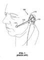
- Fig. 1 shows a perspective view that illustrates a prior-art headset 100.
- headset 100 has an elongated support member 110, a speaker 112 which is connected to one end of support member 110, and a microphone 114, which is connected to the opposite end of support member 110.
- headset 100 has a positioning member 116 that is connected to support member 110.
- Positioning member 116 which is designed to be worn over the ear, has a first section that is connected to member 110, a second angled section that is connected to the first section, and an arcuate-shaped third section that is connected to the second section.
- headsets are also commonly available that use a headband to hold the support member, and thereby the speaker and microphone, in place.
- a headband support member With a headband support member, the speaker is placed over one ear with the headband extending over and contacting the head with a padded end that rests above the opposite ear.
- soap-on-a-rope Another common type of headset, sometimes referred to as soap-on-a-rope, utilizes a speaker which is placed in or next to the ear, and a microphone which is located somewhere on the wire that connects the speaker to a telephone or computer. Although this soap-on-a-rope type headset is very compact and easy to transport, the location of the microphone, which is often clipped to the user's clothing, is susceptible to excessive background noise.
- the present invention provides a method of manufacturing headsets that utilizes a single transceiver form-factor design with a number of housing styles.
- a single transceiver form-factor with a number of housing styles, development costs, manufacturing costs, and time to market are reduced while at the same time providing a wider variety of choices to the consumer.
- the consumer can purchase additional housings without purchasing additional transceivers as the transceiver from the first headset can be used in whatever housing the consumer desires to wear.
- the method of the present invention includes the step of forming a plurality of substantially identical transceivers.
- Each transceiver has a body, a speaker transducer connected to the body that outputs sound in response to a sound signal, and a microphone transducer connected to the body that outputs an electrical speech signal in response to input sound.
- the method also includes the step of forming a number of housings with different housing styles.
- the method further includes the step of attaching the substantially identical transceivers to the housings so that transceivers are attached to different housing styles. This, in turn, allows different headsets to be built with different outer shapes, all using the same transceiver design.
- the method of the present invention may also include the steps of displaying the housing styles to a user population, and receiving an order from a user.
- the order identifies a style of housing selected by the user.
- the method of the present invention produces a collection of headsets that include a number of first and second housings.
- the first and second housings each have an inner cavity.
- the collection of headsets also includes a number of substantially-identical transceivers. The transceivers are positioned within the inner cavity of each first housing and the inner cavity of each second housing.
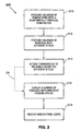
- Fig. 2 shows a flow chart that illustrates a method 200 for manufacturing headsets in accordance with the present invention.
- method 200 includes step 210 where a number of transceivers with an identical form factor are produced. (Transceivers that are intended to have the same form factor but have slight variations due to manufacturing tolerances are considered to be identical.)
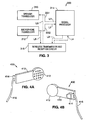
- Fig. 3 shows a block diagram that illustrates a transceiver 300 in accordance with the present invention.
- transceiver 300 includes a speaker transducer 310 that outputs sound in response to a received sound signal SS 1, and a microphone transducer 312 which outputs an electrical speech signal SS2 in response to received (input) sound.
- transceiver 300 can optionally include a signal-processing circuit 314 that is connected to the speaker and microphone transducers 310 and 312.
- Signal-processing circuit 314 can perform all or a portion of the signal processing that is required to interface transducers 310 and 312 with a communication device (not shown), such as a telephone or a computer.
- Signal processing circuit 314 can also perform other functions such as filtering, limiting, and echo cancelling.
- transceiver 300 can optionally include a wireless transmission and reception circuit 316 that is connected to signal processing circuit 314.
- Wireless transmission and reception circuit 316 transmits processed or partially processed signals from signal processing circuit 314 to the communication device, and transmits compatible signals from the communication device to signal processing circuit 314, without the use of a connecting wire.
- speaker transducer 310 and microphone transducer 312 can optionally be connected directly to wireless transmission and reception circuit 316.
- the transceivers are produced to have a single form factor.
- the form factor can have any shape, such as an elongated shape, a circular shape, a square shape, or a flat laminated shape such as the shape of a shark's fin.
- Figs. 4A and 4B show opposing perspective views of a transceiver 400 that illustrates a first example of a form factor in accordance with the present invention.
- transceiver 400 has an elongate body 410 with a first end and a second end.
- transceiver 400 also has a member 412, which accommodates a speaker transducer, that is connected to the first end of the elongate body, and a projection 414, which accommodates a microphone transducer, that is connected to the second end of elongate body 410.
- Elongate body 410 of transceiver 400 can be flexible or rigid such that a position of the speaker transducer with respect to the microphone transducer is changeable or fixed, respectively.
- an external wire 416 is connected to transceiver 400 to provide a connection to the communication device (not shown).
- Figs. 5A and 5B show opposing perspective views of a transceiver 500 that illustrates a second example of a form factor in accordance with the present invention.
- Transceiver 500 is similar to transceiver 400 and, as a result, utilizes the same reference numerals to designate the structures that are common to both transceivers.
- transceiver 500 differs from transceiver 400 in that transceiver 500 has a projection 514 that accommodates a microphone transducer. Unlike projection 414 that extends from the side of transceiver 400, projection 514 extends from the end of transceiver 500 along the longitudinal axis of transceiver 500.
- method 200 also includes step 212 where a number of housings with different styles are produced. (Steps 210 and 212 can be performed in any order, or at the same time.) Although the housing styles are different each housing is designed to operate with the transducer of the present invention.
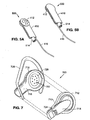
- FIGs. 6A and 6B show opposing perspective views of a housing 600 that illustrates a first example of a housing style in accordance with the present invention.
- housing 600 is a two-piece structure with a first half 610 that has an inner side 612 and a second half 614 that has an inner side 616.
- housing 600 When first and second halves 610 and 614 are connected together, housing 600 has an elongate body with a first end and a second end.
- inner sides 612 and 616 define an inner cavity 618 that has a number of openings 620 at the first end and an opening 622 at the second end.
- Inner cavity 618 receives a transceiver, such as transceiver 400 or 500, while openings 620 allow sound from the speaker transducer to pass out to the external world. Opening 622, in turn, directs sounds to the microphone transducer of the transceiver.
- any of a number of structures such as ear piece 624, can be connected to housing 600 to position housing 600 next to the ear of a user.
- FIG. 7 shows a perspective view of a housing 700 that illustrates a second example of a housing style in accordance with the present invention.
- housing 700 is also a two-piece structure with a first half 710 that has an inner side 712 and an outer side 714, and a second half 716 that has an inner side 718.
- housing 700 has an elongate body with a first end and a second end that is shorter than the elongate body of housing 600.
- inner sides 712 and 718 define an inner cavity 720 that has a number of openings 722 at the first end and an opening 724 in outer side 714 at the second end of first half 710.
- Inner cavity 720 receives a transceiver, such as transceiver 400 or 500, while openings 722 allow sound from the speaker transducer to pass out to the external world. Opening 724, in turn, directs sounds to the microphone transducer of the transceiver. Further, any of a number of structures, such as ear piece 726, can be connected to housing 700 to position housing 700 next to the ear of a user.
- FIGs. 8A and 8B show opposing perspective views of a housing 800 that illustrates a third example of a housing style in accordance with the present invention.
- housing 800 is a two-piece structure with a first half 810 that has an inner side 812 and a second half 814 that has an inner side 816.
- housing 800 When first and second halves 810 and 814 are connected together, housing 800 has a circular body.
- inner sides 812 and 816 define an inner cavity 818 that has a number of openings 820 at the centre of the body and an opening 822 in the side wall.
- Inner cavity 818 receives a transceiver, such as transceiver 400 or 500, while openings 820 allow sound from the speaker transducer to pass out to the external world. Opening 822, in turn, directs sounds to the microphone transducer of the transceiver.
- a transceiver such as transceiver 400 or 500
- housing 800 optionally includes a hollow sound conducting tube 824 that is connected to opening 822 to direct sounds to the microphone transducer.
- sound conducting tube 824 can be directly connected to the transceiver.
- any of a number of structures, such as head band 826, can be used to position housing 800 next to the ear of a user.
- Fig. 9 shows a perspective view of a housing 900 that illustrates a fourth example of a housing style in accordance with the present invention.
- housing 900 has a flexible, multi-layer laminate body 910.
- housing 900 has a cutout 912, an inner cavity 914, a first opening 916, and a number of second openings 918.
- Cutout 912 allows housing 900 to be hung from the ear of a user, while inner cavity 914 receives a transceiver, such as transceiver 400 or 500.
- first opening 916 exposes the microphone transducer of the transceiver to external sounds
- second openings 918 expose the speaker transducer to the external world.
- Fig. 10 shows a perspective view of a housing 1000 that illustrates a fifth example of a housing style in accordance with the present invention.
- housing 1000 has a flexible, single-layer laminate body 1010 with a cutout 1012 that allows housing 1000 to be hung from the ear of a user.
- housings of the present invention are not limited to these five styles and may have, as noted above, any style.
- the housings can be partially or completely formed from a material that can be cut with a pair of scissors so that the user can cut the outer sides of the housing into whatever shape is desired.
- the material of the housings can include, for example, foamed plastic, thin films, fabrics, or rubber. When the material is penetrable, no sound holes are needed in the housings.
- housings 600, 700, and 800 can also have a cut out that allows these housings to hang from the ear of a user.
- method 200 also includes step 214 where the transceivers are attached to the housings having the different housing styles.
- a number of different retaining structures can be used to attach the transceivers to the housings.
- Fig. 11 shows a perspective view that illustrates a first retaining structure 1100 in accordance with the present invention.
- first retaining structure 1100 includes a number of side walls 1110 that are connected to the inner side 1112 of a housing, such as inner side 612, 712, or 812. (Side walls 1110 need not be connected together as shown in Fig. 11 .) Side walls 1110 have a height H such that when the housing is assembled, the side walls 1110 contact or nearly contact the opposing inner side of the housing. In the preferred embodiment of the present invention, side walls 1110 are integrally formed with the housings. (Partial in register side walls can optionally be formed on the inner sides of both halves of a housing.)
- a transceiver is attached to the housing by inserting the transceiver into a region 1114 defined by side walls 1110.
- the first and second halves of the housing such as halves 610/614, 710/716, or 810/814, are connected together such that the inner sides of the housings along with side walls 1110 keep the transceiver in place.
- Fig. 12 shows a perspective view that illustrates a second retaining structure 1200 in accordance with the present invention.
- second retaining structure 1200 includes an end wall 1210, three side walls 1212 and a partial side wall 1214. Extending away from partial side wall 1214 in the same plane as partial side wall 1214 is a flexible member 1216 with a retaining clasp 1218. Further, a microphone opening 1220 and a number of speaker openings 1222 are formed in the side walls.
- retaining structure 1200 is integrally formed with the housings such that at least one of the walls is in common with the inner side of a housing.
- a transceiver is attached to the housing by pushing flexible member 1216 away from the opposing side wall, sliding the transceiver into retaining structure 1200, and then releasing flexible member 1216.
- flexible member 1216 When flexible member 1216 is released, it returns to its original position. In its original position, retaining clasp 1218 of flexible member 1216 retains the transceiver within structure 1200.
- retaining structure 1200 gives the user the ability to switch a single transceiver among a number of housing styles. For example, a user may have a number ofhousing styles and a single transceiver. The user then has the ability to place the transceiver in the preferred housing, switch styles by switching housings whenever the mood occurs or buy new a housing.
- Fig. 13 shows a side view that illustrates a third retaining structure 1300 in accordance with the present invention.
- retaining structure 1300 is a clip with first and second legs 1310 and 1312 that are connected together via a U-shaped section 1314.
- Structure 1300 which utilizes a deformable material, is formed so that first leg 1310 contacts and exerts a force against second leg 1312.
- a transceiver is attached to the housing by connecting retaining structure (clip) 1300 to a transceiver, such as transceiver 400 or 500.
- retaining structure (clip) 1300 to a transceiver, such as transceiver 400 or 500.
- legs 1310 and 1312 are spaced apart and the housing is inserted between legs 1310 and 1312.
- the legs are released. The legs, in turn, try to return to their original position, thereby clamping the housing between the legs.
- Structure 1300 offers many of the same advantages as structure 1200 in that a user can switch the transceiver among a number of different housing styles.
- Fig. 14 shows a perspective view of a headset 1400 that illustrates the use of retaining structure (clip) 1300 in accordance with the present invention.
- headset 1400 includes retaining structure 1300, transceiver 500 which is attached to structure 1300, and housing 1000 which is clamped by structure 1300.
- the transceivers can be permanently affixed to the housings.
- the transceivers can be permanently affixed using glue or other well-known adhesives.
- the clip can be part of the transceiver (or receiver if only a receiver is used), or part of the housing.
- method 200 forms a plurality of housing styles with different shapes that each utilize the same transceiver form factor.
- method 200 can include step 216 where a number of housings with different housing styles are displayed to a user population.
- the housing styles can be displayed to the user population, for example, by utilizing a web page, a catalogue, or in a traditional retail setting.
- method 200 includes step 218 where orders are received from the users.
- the orders identify the housing styles (and quantity) selected by the users.
- the orders can be received, for example, by using an interactive web page, a paper form, or in person at a retail store. Once the order is received, delivery is arranged. In a retail setting, stock on hand is sold.
- some of the manufacturing steps can be delayed until after orders are received for the headsets.
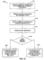
- Fig. 15 shows a flow chart that illustrates a method 1500 for manufacturing headsets in accordance with the present invention.
- Method 1500 is similar to method 200 and, as a result, utilizes the same reference numerals to designate the steps that are common to both methods.
- method 1500 is the same as method 200 up through step 212 (the formation of the housing styles), and diverges from method 200 at the next step, step 1514, where the number of housing styles is displayed to a user population.
- the housing styles can be displayed to the user population by utilizing a web page, a catalogue, or a retail setting.
- method 1500 includes step 1516 where orders are received from the users. The orders, in turn, identify the housing styles (and quantity) selected by the users. The orders can be received, for example, by using an interactive web page, a paper form, or in person at a retail shop.
- method 1500 moves to step 1520 where method 1500 determines if assembly is to be performed by the user. If assembly is to be performed by the user, method 1500 moves to step 1522 where the user is provided with either a selected housing (if only a housing was purchased) or both a selected housing and a transceiver (ifboth a housing and a transceiver were purchased). If the user receives both the selected housing and a transceiver, the user assembles the headset by attaching the transceiver to the housing.
- the user can also select or provide an example of an ornamentation to be formed on the selected housing.
- the ornamentation can include, for example, a logo, a trademark, a picture, or any design.
- self-printable labels can be included with each housing sold so that the user can design their own ornamentation. Payment for the order can be received either prior to accepting the order or following shipment of the order.
- sample headsets can be displayed to the user population with some or none of the headset components being manufactured until some time after orders for the headsets have been received. For example, every two weeks headsets could be manufactured to satisfy the orders received during the previous two weeks.
Landscapes
- Engineering & Computer Science (AREA)
- Signal Processing (AREA)
- Health & Medical Sciences (AREA)
- Otolaryngology (AREA)
- Manufacturing & Machinery (AREA)
- Physics & Mathematics (AREA)
- Acoustics & Sound (AREA)
- Telephone Set Structure (AREA)
- Headphones And Earphones (AREA)
- Surgical Instruments (AREA)
- Insulated Conductors (AREA)
- Installation Of Indoor Wiring (AREA)
Abstract
Description
- The present invention relates to headsets and, more particularly, to a headset and method of manufacturing headsets that utilize a single transceiver form-factor design with a number of different housing styles.
- A headset is a device that, when worn by a user, positions a speaker next to the user's ear and a microphone next to the user's mouth. The headset, which allows hands-free operation, is commonly worn by telephone operators and is increasingly being worn by personal computer users for telephony over the Internet, gaming, and speech recognition. In addition, more and more cell phone users are utilizing headsets.
-
Fig. 1 shows a perspective view that illustrates a prior-art headset 100. As shown inFig. 1 ,headset 100 has anelongated support member 110, aspeaker 112 which is connected to one end ofsupport member 110, and amicrophone 114, which is connected to the opposite end ofsupport member 110. - Further,
headset 100 has apositioning member 116 that is connected to supportmember 110. Positioningmember 116, which is designed to be worn over the ear, has a first section that is connected tomember 110, a second angled section that is connected to the first section, and an arcuate-shaped third section that is connected to the second section. - In addition to the ear-type headset shown in
Fig. 1 , headsets are also commonly available that use a headband to hold the support member, and thereby the speaker and microphone, in place. With a headband support member, the speaker is placed over one ear with the headband extending over and contacting the head with a padded end that rests above the opposite ear. - Another common type of headset, sometimes referred to as soap-on-a-rope, utilizes a speaker which is placed in or next to the ear, and a microphone which is located somewhere on the wire that connects the speaker to a telephone or computer. Although this soap-on-a-rope type headset is very compact and easy to transport, the location of the microphone, which is often clipped to the user's clothing, is susceptible to excessive background noise.
- The present invention provides a method of manufacturing headsets that utilizes a single transceiver form-factor design with a number of housing styles. By utilizing a single transceiver form-factor with a number of housing styles, development costs, manufacturing costs, and time to market are reduced while at the same time providing a wider variety of choices to the consumer. In addition, after buying the first headset, the consumer can purchase additional housings without purchasing additional transceivers as the transceiver from the first headset can be used in whatever housing the consumer desires to wear.
- The method of the present invention includes the step of forming a plurality of substantially identical transceivers. Each transceiver has a body, a speaker transducer connected to the body that outputs sound in response to a sound signal, and a microphone transducer connected to the body that outputs an electrical speech signal in response to input sound. The method also includes the step of forming a number of housings with different housing styles. The method further includes the step of attaching the substantially identical transceivers to the housings so that transceivers are attached to different housing styles. This, in turn, allows different headsets to be built with different outer shapes, all using the same transceiver design.
- The method of the present invention may also include the steps of displaying the housing styles to a user population, and receiving an order from a user. The order identifies a style of housing selected by the user.
- The method of the present invention produces a collection of headsets that include a number of first and second housings. The first and second housings each have an inner cavity. The collection of headsets also includes a number of substantially-identical transceivers. The transceivers are positioned within the inner cavity of each first housing and the inner cavity of each second housing.
- A better understanding of the features and advantages of the present invention will be obtained by reference to the following detailed description and accompanying drawings that set forth an illustrative embodiment in which the principles of the invention are utilized.
-
-
Fig. 1 is a perspective view illustrating a prior-art headset 100, -
Fig. 2 is a flow chart illustrating amethod 200 for manufacturing headsets in accordance with the present invention, -
Fig. 3 is a block diagram illustrating atransceiver 300 in accordance with the present invention, -
Figs. 4A and 4B are opposing perspective views of atransceiver 400 illustrating a first example of a form factor in accordance with the present invention, -
Figs. 5A and 5B are opposing perspective views of atransceiver 500 illustrating a second example of a form factor in accordance with the present invention, -
Figs. 6A and 6B are perspective views of ahousing 600 illustrating a first example of a housing style in accordance with the present invention, -
Fig. 7 is a perspective view of ahousing 700 illustrating a second example of a housing style in accordance with the present invention, -
Figs. 8A and 8B are perspective views of ahousing 800 illustrating a third example of a housing style in accordance with the present invention, -
Fig. 9 is a perspective view of ahousing 900 illustrating a fourth example of a housing style in accordance with the present invention, -
Fig. 10 is a perspective view of ahousing 1000 illustrating a fifth example of a housing style in accordance with the present invention, -
Fig.11 is a perspective view illustrating afirst retaining structure 1100 in accordance with the present invention, -
Fig. 12 is a perspective view illustrating a secondretaining structure 1200 in accordance with the present invention, -
Fig. 13 is a side view illustrating athird retaining structure 1300 in accordance with the present invention, -
Fig. 14 is a perspective view of aheadset 1400 illustrating the use of a retaining structure (clip) 1300 in accordance with the present invention, and -
Fig. 15 is a flow chart illustrating amethod 1500 for manufacturing headsets in accordance with the present invention. - -
Fig. 2 shows a flow chart that illustrates amethod 200 for manufacturing headsets in accordance with the present invention. As shown inFig. 2 ,method 200 includesstep 210 where a number of transceivers with an identical form factor are produced. (Transceivers that are intended to have the same form factor but have slight variations due to manufacturing tolerances are considered to be identical.) -
Fig. 3 shows a block diagram that illustrates atransceiver 300 in accordance with the present invention. As shown inFig. 3 ,transceiver 300 includes aspeaker transducer 310 that outputs sound in response to a received sound signal SS 1, and amicrophone transducer 312 which outputs an electrical speech signal SS2 in response to received (input) sound. - In addition, as shown by dashed lines L1 and L2,
transceiver 300 can optionally include a signal-processing circuit 314 that is connected to the speaker andmicrophone transducers processing circuit 314 can perform all or a portion of the signal processing that is required to interfacetransducers Signal processing circuit 314 can also perform other functions such as filtering, limiting, and echo cancelling. - Further, as shown by dashed lines L3 and L4,
transceiver 300 can optionally include a wireless transmission andreception circuit 316 that is connected tosignal processing circuit 314. Wireless transmission andreception circuit 316 transmits processed or partially processed signals fromsignal processing circuit 314 to the communication device, and transmits compatible signals from the communication device tosignal processing circuit 314, without the use of a connecting wire. In addition, as shown by dashed lines L5 and L6,speaker transducer 310 andmicrophone transducer 312 can optionally be connected directly to wireless transmission andreception circuit 316. - As noted above, the transceivers are produced to have a single form factor. Although the transceivers are produced to have a single form factor, the form factor can have any shape, such as an elongated shape, a circular shape, a square shape, or a flat laminated shape such as the shape of a shark's fin.
-
Figs. 4A and 4B show opposing perspective views of atransceiver 400 that illustrates a first example of a form factor in accordance with the present invention. As shown inFigs. 4A and 4B ,transceiver 400 has anelongate body 410 with a first end and a second end. In addition,transceiver 400 also has amember 412, which accommodates a speaker transducer, that is connected to the first end of the elongate body, and aprojection 414, which accommodates a microphone transducer, that is connected to the second end ofelongate body 410. -
Elongate body 410 oftransceiver 400 can be flexible or rigid such that a position of the speaker transducer with respect to the microphone transducer is changeable or fixed, respectively. In addition, when the transceiver does not have a wireless transmission and reception circuit, anexternal wire 416 is connected to transceiver 400 to provide a connection to the communication device (not shown). -
Figs. 5A and 5B show opposing perspective views of atransceiver 500 that illustrates a second example of a form factor in accordance with the present invention.Transceiver 500 is similar totransceiver 400 and, as a result, utilizes the same reference numerals to designate the structures that are common to both transceivers. - As shown in
Figs. 5A and 5B ,transceiver 500 differs fromtransceiver 400 in thattransceiver 500 has aprojection 514 that accommodates a microphone transducer. Unlikeprojection 414 that extends from the side oftransceiver 400,projection 514 extends from the end oftransceiver 500 along the longitudinal axis oftransceiver 500. - In addition to the above, rather than using a number of transceivers with a single form factor, a number of receivers with the same form factor can alternately be used.
- Returning to
Fig. 2 ,method 200 also includesstep 212 where a number of housings with different styles are produced. (Steps -
Figs. 6A and 6B show opposing perspective views of ahousing 600 that illustrates a first example of a housing style in accordance with the present invention. As shown inFigs. 6A and 6B ,housing 600 is a two-piece structure with afirst half 610 that has aninner side 612 and asecond half 614 that has aninner side 616. - When first and
second halves housing 600 has an elongate body with a first end and a second end. In addition,inner sides inner cavity 618 that has a number ofopenings 620 at the first end and anopening 622 at the second end. -
Inner cavity 618 receives a transceiver, such astransceiver openings 620 allow sound from the speaker transducer to pass out to the external world.Opening 622, in turn, directs sounds to the microphone transducer of the transceiver. Further, any of a number of structures, such asear piece 624, can be connected tohousing 600 to positionhousing 600 next to the ear of a user. -
Fig. 7 shows a perspective view of ahousing 700 that illustrates a second example of a housing style in accordance with the present invention. As shown inFig. 7 ,housing 700 is also a two-piece structure with afirst half 710 that has aninner side 712 and anouter side 714, and asecond half 716 that has aninner side 718. - When first and
second halves housing 700 has an elongate body with a first end and a second end that is shorter than the elongate body ofhousing 600. In addition,inner sides inner cavity 720 that has a number ofopenings 722 at the first end and anopening 724 inouter side 714 at the second end offirst half 710. -
Inner cavity 720 receives a transceiver, such astransceiver openings 722 allow sound from the speaker transducer to pass out to the external world.
Opening 724, in turn, directs sounds to the microphone transducer of the transceiver.
Further, any of a number of structures, such asear piece 726, can be connected tohousing 700 to positionhousing 700 next to the ear of a user. -
Figs. 8A and 8B show opposing perspective views of ahousing 800 that illustrates a third example of a housing style in accordance with the present invention. As shown inFigs. 8A and 8B ,housing 800 is a two-piece structure with afirst half 810 that has aninner side 812 and asecond half 814 that has aninner side 816. - When first and
second halves housing 800 has a circular body. In addition,inner sides inner cavity 818 that has a number ofopenings 820 at the centre of the body and anopening 822 in the side wall. -
Inner cavity 818 receives a transceiver, such astransceiver openings 820 allow sound from the speaker transducer to pass out to the external world.
Opening 822, in turn, directs sounds to the microphone transducer of the transceiver. - In addition,
housing 800 optionally includes a hollowsound conducting tube 824 that is connected to opening 822 to direct sounds to the microphone transducer. Optionally,sound conducting tube 824 can be directly connected to the transceiver. Further, any of a number of structures, such ashead band 826, can be used to positionhousing 800 next to the ear of a user. -
Fig. 9 shows a perspective view of ahousing 900 that illustrates a fourth example of a housing style in accordance with the present invention. As shown inFig. 9 ,housing 900 has a flexible,multi-layer laminate body 910. In addition,housing 900 has acutout 912, aninner cavity 914, afirst opening 916, and a number ofsecond openings 918.Cutout 912 allowshousing 900 to be hung from the ear of a user, whileinner cavity 914 receives a transceiver, such astransceiver first opening 916 exposes the microphone transducer of the transceiver to external sounds, whilesecond openings 918 expose the speaker transducer to the external world. -
Fig. 10 shows a perspective view of ahousing 1000 that illustrates a fifth example of a housing style in accordance with the present invention. As shown inFig.10 ,housing 1000 has a flexible, single-layer laminate body 1010 with acutout 1012 that allowshousing 1000 to be hung from the ear of a user. - Although five examples of housing styles have been discussed, the housings of the present invention are not limited to these five styles and may have, as noted above, any style. In addition, the housings can be partially or completely formed from a material that can be cut with a pair of scissors so that the user can cut the outer sides of the housing into whatever shape is desired. The material of the housings can include, for example, foamed plastic, thin films, fabrics, or rubber. When the material is penetrable, no sound holes are needed in the housings. Further, in addition to
housings housings - Returning to
Fig. 2 ,method 200 also includesstep 214 where the transceivers are attached to the housings having the different housing styles. A number of different retaining structures can be used to attach the transceivers to the housings.Fig. 11 shows a perspective view that illustrates afirst retaining structure 1100 in accordance with the present invention. - As shown in
Fig. 11 ,first retaining structure 1100 includes a number ofside walls 1110 that are connected to theinner side 1112 of a housing, such asinner side Side walls 1110 need not be connected together as shown inFig. 11 .)Side walls 1110 have a height H such that when the housing is assembled, theside walls 1110 contact or nearly contact the opposing inner side of the housing. In the preferred embodiment of the present invention,side walls 1110 are integrally formed with the housings. (Partial in register side walls can optionally be formed on the inner sides of both halves of a housing.) - In this example, a transceiver is attached to the housing by inserting the transceiver into a
region 1114 defined byside walls 1110. After this, the first and second halves of the housing, such ashalves 610/614, 710/716, or 810/814, are connected together such that the inner sides of the housings along withside walls 1110 keep the transceiver in place. -
Fig. 12 shows a perspective view that illustrates asecond retaining structure 1200 in accordance with the present invention. As shown inFig. 12 ,second retaining structure 1200 includes anend wall 1210, threeside walls 1212 and apartial side wall 1214.
Extending away frompartial side wall 1214 in the same plane aspartial side wall 1214 is aflexible member 1216 with a retainingclasp 1218. Further, amicrophone opening 1220 and a number ofspeaker openings 1222 are formed in the side walls. In the preferred embodiment of the present invention, retainingstructure 1200 is integrally formed with the housings such that at least one of the walls is in common with the inner side of a housing. - In this example, a transceiver is attached to the housing by pushing
flexible member 1216 away from the opposing side wall, sliding the transceiver into retainingstructure 1200, and then releasingflexible member 1216. Whenflexible member 1216 is released, it returns to its original position. In its original position, retainingclasp 1218 offlexible member 1216 retains the transceiver withinstructure 1200. - The advantage of retaining
structure 1200 is that the transceivers can be easily inserted; either during the manufacturing process or by the user themselves. In addition, retainingstructure 1200 gives the user the ability to switch a single transceiver among a number of housing styles. For example, a user may have a number ofhousing styles and a single transceiver. The user then has the ability to place the transceiver in the preferred housing, switch styles by switching housings whenever the mood occurs or buy new a housing. -
Fig. 13 shows a side view that illustrates athird retaining structure 1300 in accordance with the present invention. As shown inFig. 13 , retainingstructure 1300 is a clip with first andsecond legs U-shaped section 1314.Structure 1300, which utilizes a deformable material, is formed so thatfirst leg 1310 contacts and exerts a force againstsecond leg 1312. - In this example, a transceiver is attached to the housing by connecting retaining structure (clip) 1300 to a transceiver, such as
transceiver legs legs Structure 1300 offers many of the same advantages asstructure 1200 in that a user can switch the transceiver among a number of different housing styles. -
Fig. 14 shows a perspective view of aheadset 1400 that illustrates the use of retaining structure (clip) 1300 in accordance with the present invention. As shown inFig. 14 ,headset 1400 includes retainingstructure 1300,transceiver 500 which is attached to structure 1300, andhousing 1000 which is clamped bystructure 1300. - Alternately, rather than using retaining
structures - Thus,
method 200 forms a plurality of housing styles with different shapes that each utilize the same transceiver form factor. By utilizing a single transceiver form-factor with a number of housing styles, development costs, manufacturing costs, and time to market are reduced while at the same time providing a wider variety of choices to the consumer. - In addition to providing the user with a wider variety of housing styles, the present invention also allows the end user to view the available styles, and order the desired style. As shown by dashed
line 2A inFig. 2 ,method 200 can include step 216 where a number of housings with different housing styles are displayed to a user population.
The housing styles can be displayed to the user population, for example, by utilizing a web page, a catalogue, or in a traditional retail setting. In addition,method 200 includesstep 218 where orders are received from the users. - The orders, in turn, identify the housing styles (and quantity) selected by the users. The orders can be received, for example, by using an interactive web page, a paper form, or in person at a retail store. Once the order is received, delivery is arranged.
In a retail setting, stock on hand is sold. - In accordance with the present invention, rather than displaying the housings to the user population after the headsets have been assembled, some of the manufacturing steps can be delayed until after orders are received for the headsets.
-
Fig. 15 shows a flow chart that illustrates amethod 1500 for manufacturing headsets in accordance with the present invention.Method 1500 is similar tomethod 200 and, as a result, utilizes the same reference numerals to designate the steps that are common to both methods. - As shown in
Fig. 15 ,method 1500 is the same asmethod 200 up through step 212 (the formation of the housing styles), and diverges frommethod 200 at the next step,step 1514, where the number of housing styles is displayed to a user population. As inmethod 200, the housing styles can be displayed to the user population by utilizing a web page, a catalogue, or a retail setting. In addition,method 1500 includesstep 1516 where orders are received from the users. The orders, in turn, identify the housing styles (and quantity) selected by the users. The orders can be received, for example, by using an interactive web page, a paper form, or in person at a retail shop. - Next,
method 1500 moves to step 1520 wheremethod 1500 determines if assembly is to be performed by the user. If assembly is to be performed by the user,method 1500 moves to step 1522 where the user is provided with either a selected housing (if only a housing was purchased) or both a selected housing and a transceiver (ifboth a housing and a transceiver were purchased). If the user receives both the selected housing and a transceiver, the user assembles the headset by attaching the transceiver to the housing. - If assembly is not to be performed by the user,
method 1500 moves to step 1524 where transceivers are attached to the housings based on the orders received during a previous time period. For example, every two weeks transceivers could be attached to the ordered housings to form completed headsets to satisfy the orders received during the previous two weeks. By attaching transceivers on an as-ordered basis, the costs to assemble the headsets can be more related to the headsets that are being sold. By allowing the user to finish the final assembly, the costs to assemble the headsets can be largely eliminated. - In addition to selecting a housing style, the user can also select or provide an example of an ornamentation to be formed on the selected housing. The ornamentation can include, for example, a logo, a trademark, a picture, or any design. Alternately, self-printable labels can be included with each housing sold so that the user can design their own ornamentation. Payment for the order can be received either prior to accepting the order or following shipment of the order.
- In addition, sample headsets can be displayed to the user population with some or none of the headset components being manufactured until some time after orders for the headsets have been received. For example, every two weeks headsets could be manufactured to satisfy the orders received during the previous two weeks.
- It should be understood that various alternatives to the embodiment of the invention described herein may be employed in practising the invention. Thus, it is intended that the following claims define the scope of the invention and that methods and structures within the scope of these claims and their equivalents be covered thereby.
Claims (18)
- A method for manufacturing headsets, the method comprising the steps of:- forming a plurality of identical bodies, each body having a speaker transducer that outputs sound in response to a sound signal and a microphone transducer for receiving the speech of the user of the headset, said microphone transducer outputting a speech signal in reponse to sound;- forming a number of types of housings, each type of housing having an inner cavity configured to receive a body and having a different outer shape; and- mounting a body in the inner cavity of the housing so that bodies are mounted in different types of housings.
- The method of claim 1, wherein the body further includes a signal processing circuit connected to the speaker and microphone transducers.
- The method of claim 2, wherein the body further includes a wireless transmission and reception circuit connected to the signal processing circuit
- The method of claim 1, wherein the body further includes a wireless transmission and reception circuit connected to the speaker and microphone transducers.
- The method of claim 1, wherein the body has a shape selected from the group consisting of an elongated shape, a circular shape, a flat laminated shape, and a square shape.
- The method of claim 1, wherein the step of forming a number of housings includes the step of forming a retaining structure inside each housing, and the step of mounting includes the step of inserting the bodies into the retaining structure.
- The method of claim 6, wherein the retaining structure includes a number of side walls that extend away from an inner side of the housing, and wherein the step of inserting includes the step of placing the body into a region defined by the number of side walls.
- The method of claim 6, wherein the retaining structure includes a number of side walls, a partial side wall connected to the number of side walls, a flexible member that extends away from the partial side wall in a plane of the partial side wall, and a retaining clasp connected to the flexible member, and wherein the step of mounting includes the step of sliding the body into a region defined by the number of side walls and the partial side wall.
- The method of claim 1, wherein the housings have first and second sides, and a body is mounted in a housing by affixing the body to the first side of a housing, and connecting the first and second sides of the housing together.
- Headsets comprising:- a number of first housings, each first housing having an inner cavity;- a number of second housings, each second housing having an inner cavity;- the first housings and the second housings having different shapes; and- a number of identical bodies with a body being positioned within the inner cavity of each first housing and the inner cavity of each second housing, each body having a speaker transducer that outputs sound in response to a sound signal and a microphone transducer for receiving the speech of the user of the headset, said microphone transducer outputting a speech signal in response to sound.
- The headsets of claim 10, wherein the body further includes a signal processing circuit connected to the speaker and microphone transducers.
- The headsets of claim 11, wherein the body further includes a wireless transmission and reception circuit connected to the signal processing circuit
- The headsets of claim 10, wherein the body further includes a wireless transmission and reception circuit connected to the speaker and microphone transducers.
- The headsets of claim 10, wherein the inner cavity of each first housing is bounded by a flexible member with a retaining clasp that retains the body in the inner cavity.
- The headsets of claim 10, wherein each first housing has first and second sides.
- The headsets of claim 10, wherein the inner cavity of each first housing is bounded by four side walls that extend away from the first side of a housing.
- The headsets of any one of the claims 10-16, wherein the speaker transducer is arranged at a first end of the body and the microphone transducer is arranged at a second end of the body.
- The headset of claim 17, wherein the body is elongate and rigid such that a position of the speaker transducer with respect to the microphone transducer is fixed.
Applications Claiming Priority (3)
| Application Number | Priority Date | Filing Date | Title |
|---|---|---|---|
| US09/712,867 US6760458B1 (en) | 2000-11-15 | 2000-11-15 | Headset and method of manufacturing headsets that utilize a single transceiver form-factor design with a number of different housing styles |
| US712867 | 2000-11-15 | ||
| PCT/DK2001/000754 WO2002041608A1 (en) | 2000-11-15 | 2001-11-15 | Headset |
Publications (2)
| Publication Number | Publication Date |
|---|---|
| EP1334603A1 EP1334603A1 (en) | 2003-08-13 |
| EP1334603B1 true EP1334603B1 (en) | 2009-09-02 |
Family
ID=24863877
Family Applications (1)
| Application Number | Title | Priority Date | Filing Date |
|---|---|---|---|
| EP01996964A Expired - Lifetime EP1334603B1 (en) | 2000-11-15 | 2001-11-15 | Headset |
Country Status (9)
| Country | Link |
|---|---|
| US (2) | US6760458B1 (en) |
| EP (1) | EP1334603B1 (en) |
| JP (1) | JP3973555B2 (en) |
| KR (1) | KR100770618B1 (en) |
| CN (1) | CN1213586C (en) |
| AT (1) | ATE441997T1 (en) |
| AU (1) | AU2002223496A1 (en) |
| DE (1) | DE60139798D1 (en) |
| WO (1) | WO2002041608A1 (en) |
Families Citing this family (29)
| Publication number | Priority date | Publication date | Assignee | Title |
|---|---|---|---|---|
| US8204435B2 (en) * | 2003-05-28 | 2012-06-19 | Broadcom Corporation | Wireless headset supporting enhanced call functions |
| US20050136839A1 (en) * | 2003-05-28 | 2005-06-23 | Nambirajan Seshadri | Modular wireless multimedia device |
| USD509823S1 (en) * | 2003-11-13 | 2005-09-20 | Samsung Electronics Co., Ltd. | Wireless headset |
| USD527376S1 (en) * | 2004-03-24 | 2006-08-29 | Steven Swain | Headset |
| USD512991S1 (en) * | 2004-05-03 | 2005-12-20 | Sony Ericsson Mobile Communications Ab | Headset |
| USD529021S1 (en) * | 2005-01-14 | 2006-09-26 | Gn Netcom A/S | Wireless headset |
| US7778601B2 (en) * | 2005-01-24 | 2010-08-17 | Broadcom Corporation | Pairing modular wireless earpiece/microphone (HEADSET) to a serviced base portion and subsequent access thereto |
| US20060166717A1 (en) * | 2005-01-24 | 2006-07-27 | Nambirajan Seshadri | Managing access of modular wireless earpiece/microphone (HEADSET) to public/private servicing base station |
| US7555318B2 (en) * | 2005-02-15 | 2009-06-30 | Broadcom Corporation | Handover of call serviced by modular ear-piece/microphone between servicing base portions |
| CA111713S (en) * | 2005-06-30 | 2006-08-14 | Gennum Corp | Headset for an electronic device |
| USD541262S1 (en) * | 2005-12-09 | 2007-04-24 | Motorola, Inc. | Communication device |
| USD566693S1 (en) * | 2006-04-06 | 2008-04-15 | Gn Netcom A/S | Wireless headset |
| KR100757462B1 (en) * | 2006-07-14 | 2007-09-11 | 삼성전자주식회사 | earphone |
| TWD119391S1 (en) * | 2006-09-05 | 2007-10-11 | 愛迪聲科技有限公司 | Wireless headset |
| CA118213S (en) * | 2006-11-10 | 2007-12-13 | Gennum Corp | Headset for an electronic device |
| TWD125181S1 (en) * | 2007-02-09 | 2008-10-01 | 諾基亞股份有限公司 | Carholder |
| USD585430S1 (en) * | 2007-07-13 | 2009-01-27 | Lg Electronics Inc. | Headset for bluetooth |
| USD583805S1 (en) * | 2007-08-08 | 2008-12-30 | Nokia Corporation | Headset body, earclip of a headset and cover for a headset |
| USD581900S1 (en) * | 2007-12-21 | 2008-12-02 | Plantronics, Inc. | Communications headset |
| US8355515B2 (en) * | 2008-04-07 | 2013-01-15 | Sony Computer Entertainment Inc. | Gaming headset and charging method |
| TWI433554B (en) | 2009-03-18 | 2014-04-01 | Htc Corp | Ear piece |
| USD634736S1 (en) | 2010-01-29 | 2011-03-22 | Motorola Mobility, Inc. | Headset for a communication device |
| USD653244S1 (en) | 2010-03-18 | 2012-01-31 | Gn Netcom A/S | Ear piece |
| CN104219357A (en) * | 2013-05-30 | 2014-12-17 | 巍世科技有限公司 | Voice instruction network telephone and operation method thereof |
| US10021476B2 (en) * | 2014-08-26 | 2018-07-10 | Timothy Val Kolton | Earphone with interchangeable housing |
| USD747295S1 (en) * | 2014-12-23 | 2016-01-12 | Intel Corporation | In-ear headphone |
| USD790505S1 (en) * | 2015-06-18 | 2017-06-27 | Hand Held Products, Inc. | Wireless audio headset |
| USD944228S1 (en) * | 2021-03-16 | 2022-02-22 | Shenzhen Quanmeng Technology Co., Ltd. | Earphone |
| KR102473619B1 (en) * | 2022-07-18 | 2022-12-01 | 김종호 | Headset manufacturing method |
Citations (1)
| Publication number | Priority date | Publication date | Assignee | Title |
|---|---|---|---|---|
| EP0583900A1 (en) * | 1992-08-19 | 1994-02-23 | Sony Corporation | Improved headphone apparatus |
Family Cites Families (17)
| Publication number | Priority date | Publication date | Assignee | Title |
|---|---|---|---|---|
| US3826987A (en) * | 1973-05-30 | 1974-07-30 | J Stevens | Miniature radio receiver |
| US4302635A (en) | 1980-01-04 | 1981-11-24 | Koss Corporation | Headphone construction |
| US4319095A (en) | 1980-06-06 | 1982-03-09 | Northern Telecom Limited | Telephone handset transducer mounting |
| US4901355A (en) * | 1986-08-04 | 1990-02-13 | Moore Michael R | Combination multiple supported variable position audio intake control devices |
| JPH06237499A (en) * | 1993-02-09 | 1994-08-23 | Sony Corp | Headphone |
| FR2706103B1 (en) * | 1993-06-03 | 1997-01-31 | Ericsson Ge Mobile Communicat | Radiotelephone apparatus. |
| DE4343702C1 (en) * | 1993-12-21 | 1995-03-09 | Siemens Audiologische Technik | Hearing aid worn on the head |
| US5581627A (en) | 1994-08-03 | 1996-12-03 | Bowser; Bradford E. | Convertible cover headphones |
| US5960094A (en) * | 1996-01-24 | 1999-09-28 | Gn Netcom, Inc. | Communications headset |
| US6347218B1 (en) | 1996-02-28 | 2002-02-12 | Nokia Mobile Phones Limited | Electronic device with housing supplement |
| US6038329A (en) * | 1996-07-08 | 2000-03-14 | Lee; Youn M. | Earphone device |
| US6230029B1 (en) * | 1998-01-07 | 2001-05-08 | Advanced Mobile Solutions, Inc. | Modular wireless headset system |
| US6490362B1 (en) * | 1998-06-10 | 2002-12-03 | Wren Clegg | External ear speaker ear-hook boom microphone |
| DE19837765A1 (en) | 1998-08-20 | 2000-02-24 | Georg Floeh | Protective hinged two-part cover for mobile telephones made from hard material protects from damage such as scratches on display panels and shocks during physical movement. |
| US6084976A (en) * | 1999-06-11 | 2000-07-04 | Lin; Chung-Yu | Earphone without impulse noise and conductive hearing loss |
| US6374090B1 (en) * | 1999-11-16 | 2002-04-16 | William E. Morales | Cellular telephone handset holder |
| US6373942B1 (en) | 2000-04-07 | 2002-04-16 | Paul M. Braund | Hands-free communication device |
-
2000
- 2000-11-15 US US09/712,867 patent/US6760458B1/en not_active Expired - Lifetime
-
2001
- 2001-11-15 KR KR1020037006452A patent/KR100770618B1/en not_active Expired - Fee Related
- 2001-11-15 AU AU2002223496A patent/AU2002223496A1/en not_active Abandoned
- 2001-11-15 AT AT01996964T patent/ATE441997T1/en not_active IP Right Cessation
- 2001-11-15 DE DE60139798T patent/DE60139798D1/en not_active Expired - Lifetime
- 2001-11-15 JP JP2002543208A patent/JP3973555B2/en not_active Expired - Lifetime
- 2001-11-15 EP EP01996964A patent/EP1334603B1/en not_active Expired - Lifetime
- 2001-11-15 CN CNB018189210A patent/CN1213586C/en not_active Expired - Fee Related
- 2001-11-15 WO PCT/DK2001/000754 patent/WO2002041608A1/en not_active Ceased
-
2004
- 2004-04-12 US US10/823,345 patent/US20040190744A1/en not_active Abandoned
Patent Citations (1)
| Publication number | Priority date | Publication date | Assignee | Title |
|---|---|---|---|---|
| EP0583900A1 (en) * | 1992-08-19 | 1994-02-23 | Sony Corporation | Improved headphone apparatus |
Also Published As
| Publication number | Publication date |
|---|---|
| JP2004514345A (en) | 2004-05-13 |
| CN1213586C (en) | 2005-08-03 |
| CN1475071A (en) | 2004-02-11 |
| DE60139798D1 (en) | 2009-10-15 |
| US6760458B1 (en) | 2004-07-06 |
| AU2002223496A1 (en) | 2002-05-27 |
| EP1334603A1 (en) | 2003-08-13 |
| KR100770618B1 (en) | 2007-10-29 |
| WO2002041608A1 (en) | 2002-05-23 |
| JP3973555B2 (en) | 2007-09-12 |
| ATE441997T1 (en) | 2009-09-15 |
| US20040190744A1 (en) | 2004-09-30 |
| KR20030048142A (en) | 2003-06-18 |
| HK1060952A1 (en) | 2004-08-27 |
Similar Documents
| Publication | Publication Date | Title |
|---|---|---|
| EP1334603B1 (en) | Headset | |
| US4720857A (en) | Miniaturized headset for two-way voice communication | |
| US7031485B2 (en) | Ear mounting assembly for electronic component | |
| US6091832A (en) | Wearable personal audio loop apparatus | |
| US7680267B2 (en) | Headset with a retractable speaker portion | |
| US7123737B2 (en) | Ear clasp headset | |
| US5909498A (en) | Transducer device for use with communication apparatus | |
| US6373942B1 (en) | Hands-free communication device | |
| US20020065115A1 (en) | Accessory for a communication terminal | |
| JP2000341778A (en) | Handset using bone conduction speaker | |
| US20240236557A1 (en) | Smart glasses with sound enhancement function | |
| EP0651546B1 (en) | Cellular radio telephone set | |
| EP2372984A1 (en) | Communication item as a pendant on a choker | |
| US20030083111A1 (en) | Compact mobile phone device with hook | |
| US20040082359A1 (en) | Earprone system for mobile phone | |
| EP2378744A1 (en) | Communication item as a pendant on a necklace | |
| JP3504657B1 (en) | Ear wearing structure and rhythm generator | |
| WO1999059314A1 (en) | Arm-attached portable phone | |
| GB2417166A (en) | A headset assembly | |
| JP2002009919A (en) | Mounting article to body | |
| US6785385B2 (en) | Safety helmet structure with a hand-free receiver | |
| JP2002044770A (en) | Set of ear attachment for earphone or the like and hands-free earphone or the like | |
| JP3048283U (en) | Ancillary equipment for portable communication receiver | |
| JPH11164382A (en) | Earphone with microphone | |
| JPH0597189U (en) | Bone conduction transmitter / receiver |
Legal Events
| Date | Code | Title | Description |
|---|---|---|---|
| PUAI | Public reference made under article 153(3) epc to a published international application that has entered the european phase |
Free format text: ORIGINAL CODE: 0009012 |
|
| 17P | Request for examination filed |
Effective date: 20030508 |
|
| AK | Designated contracting states |
Designated state(s): AT BE CH CY DE DK ES FI FR GB GR IE IT LI LU MC NL PT SE TR |
|
| AX | Request for extension of the european patent |
Extension state: AL LT LV MK RO SI |
|
| GRAP | Despatch of communication of intention to grant a patent |
Free format text: ORIGINAL CODE: EPIDOSNIGR1 |
|
| RIN1 | Information on inventor provided before grant (corrected) |
Inventor name: BOGESKOV-JENSEN, TOM Inventor name: LARSEN, JAN |
|
| GRAS | Grant fee paid |
Free format text: ORIGINAL CODE: EPIDOSNIGR3 |
|
| GRAA | (expected) grant |
Free format text: ORIGINAL CODE: 0009210 |
|
| AK | Designated contracting states |
Kind code of ref document: B1 Designated state(s): AT BE CH CY DE DK ES FI FR GB GR IE IT LI LU MC NL PT SE TR |
|
| REG | Reference to a national code |
Ref country code: CH Ref legal event code: EP |
|
| REG | Reference to a national code |
Ref country code: IE Ref legal event code: FG4D |
|
| REF | Corresponds to: |
Ref document number: 60139798 Country of ref document: DE Date of ref document: 20091015 Kind code of ref document: P |
|
| PG25 | Lapsed in a contracting state [announced via postgrant information from national office to epo] |
Ref country code: FI Free format text: LAPSE BECAUSE OF FAILURE TO SUBMIT A TRANSLATION OF THE DESCRIPTION OR TO PAY THE FEE WITHIN THE PRESCRIBED TIME-LIMIT Effective date: 20090902 Ref country code: SE Free format text: LAPSE BECAUSE OF FAILURE TO SUBMIT A TRANSLATION OF THE DESCRIPTION OR TO PAY THE FEE WITHIN THE PRESCRIBED TIME-LIMIT Effective date: 20090902 |
|
| NLV1 | Nl: lapsed or annulled due to failure to fulfill the requirements of art. 29p and 29m of the patents act | ||
| PG25 | Lapsed in a contracting state [announced via postgrant information from national office to epo] |
Ref country code: NL Free format text: LAPSE BECAUSE OF FAILURE TO SUBMIT A TRANSLATION OF THE DESCRIPTION OR TO PAY THE FEE WITHIN THE PRESCRIBED TIME-LIMIT Effective date: 20090902 |
|
| PG25 | Lapsed in a contracting state [announced via postgrant information from national office to epo] |
Ref country code: CY Free format text: LAPSE BECAUSE OF FAILURE TO SUBMIT A TRANSLATION OF THE DESCRIPTION OR TO PAY THE FEE WITHIN THE PRESCRIBED TIME-LIMIT Effective date: 20090902 |
|
| PG25 | Lapsed in a contracting state [announced via postgrant information from national office to epo] |
Ref country code: ES Free format text: LAPSE BECAUSE OF FAILURE TO SUBMIT A TRANSLATION OF THE DESCRIPTION OR TO PAY THE FEE WITHIN THE PRESCRIBED TIME-LIMIT Effective date: 20091213 Ref country code: PT Free format text: LAPSE BECAUSE OF FAILURE TO SUBMIT A TRANSLATION OF THE DESCRIPTION OR TO PAY THE FEE WITHIN THE PRESCRIBED TIME-LIMIT Effective date: 20100104 |
|
| PG25 | Lapsed in a contracting state [announced via postgrant information from national office to epo] |
Ref country code: AT Free format text: LAPSE BECAUSE OF FAILURE TO SUBMIT A TRANSLATION OF THE DESCRIPTION OR TO PAY THE FEE WITHIN THE PRESCRIBED TIME-LIMIT Effective date: 20090902 Ref country code: BE Free format text: LAPSE BECAUSE OF FAILURE TO SUBMIT A TRANSLATION OF THE DESCRIPTION OR TO PAY THE FEE WITHIN THE PRESCRIBED TIME-LIMIT Effective date: 20090902 Ref country code: MC Free format text: LAPSE BECAUSE OF NON-PAYMENT OF DUE FEES Effective date: 20091130 |
|
| REG | Reference to a national code |
Ref country code: CH Ref legal event code: PL |
|
| PLBE | No opposition filed within time limit |
Free format text: ORIGINAL CODE: 0009261 |
|
| STAA | Information on the status of an ep patent application or granted ep patent |
Free format text: STATUS: NO OPPOSITION FILED WITHIN TIME LIMIT |
|
| PG25 | Lapsed in a contracting state [announced via postgrant information from national office to epo] |
Ref country code: DK Free format text: LAPSE BECAUSE OF FAILURE TO SUBMIT A TRANSLATION OF THE DESCRIPTION OR TO PAY THE FEE WITHIN THE PRESCRIBED TIME-LIMIT Effective date: 20090902 |
|
| 26N | No opposition filed |
Effective date: 20100603 |
|
| PG25 | Lapsed in a contracting state [announced via postgrant information from national office to epo] |
Ref country code: IE Free format text: LAPSE BECAUSE OF NON-PAYMENT OF DUE FEES Effective date: 20091115 Ref country code: LI Free format text: LAPSE BECAUSE OF NON-PAYMENT OF DUE FEES Effective date: 20091130 Ref country code: CH Free format text: LAPSE BECAUSE OF NON-PAYMENT OF DUE FEES Effective date: 20091130 Ref country code: GR Free format text: LAPSE BECAUSE OF FAILURE TO SUBMIT A TRANSLATION OF THE DESCRIPTION OR TO PAY THE FEE WITHIN THE PRESCRIBED TIME-LIMIT Effective date: 20091203 |
|
| PG25 | Lapsed in a contracting state [announced via postgrant information from national office to epo] |
Ref country code: IT Free format text: LAPSE BECAUSE OF FAILURE TO SUBMIT A TRANSLATION OF THE DESCRIPTION OR TO PAY THE FEE WITHIN THE PRESCRIBED TIME-LIMIT Effective date: 20090902 |
|
| PG25 | Lapsed in a contracting state [announced via postgrant information from national office to epo] |
Ref country code: LU Free format text: LAPSE BECAUSE OF NON-PAYMENT OF DUE FEES Effective date: 20091115 |
|
| PG25 | Lapsed in a contracting state [announced via postgrant information from national office to epo] |
Ref country code: TR Free format text: LAPSE BECAUSE OF FAILURE TO SUBMIT A TRANSLATION OF THE DESCRIPTION OR TO PAY THE FEE WITHIN THE PRESCRIBED TIME-LIMIT Effective date: 20090902 |
|
| REG | Reference to a national code |
Ref country code: FR Ref legal event code: PLFP Year of fee payment: 15 |
|
| REG | Reference to a national code |
Ref country code: FR Ref legal event code: PLFP Year of fee payment: 16 |
|
| REG | Reference to a national code |
Ref country code: FR Ref legal event code: PLFP Year of fee payment: 17 |
|
| PGFP | Annual fee paid to national office [announced via postgrant information from national office to epo] |
Ref country code: DE Payment date: 20191120 Year of fee payment: 19 |
|
| PGFP | Annual fee paid to national office [announced via postgrant information from national office to epo] |
Ref country code: FR Payment date: 20191115 Year of fee payment: 19 |
|
| PGFP | Annual fee paid to national office [announced via postgrant information from national office to epo] |
Ref country code: GB Payment date: 20191118 Year of fee payment: 19 |
|
| REG | Reference to a national code |
Ref country code: DE Ref legal event code: R119 Ref document number: 60139798 Country of ref document: DE |
|
| GBPC | Gb: european patent ceased through non-payment of renewal fee |
Effective date: 20201115 |
|
| PG25 | Lapsed in a contracting state [announced via postgrant information from national office to epo] |
Ref country code: FR Free format text: LAPSE BECAUSE OF NON-PAYMENT OF DUE FEES Effective date: 20201130 |
|
| PG25 | Lapsed in a contracting state [announced via postgrant information from national office to epo] |
Ref country code: GB Free format text: LAPSE BECAUSE OF NON-PAYMENT OF DUE FEES Effective date: 20201115 Ref country code: DE Free format text: LAPSE BECAUSE OF NON-PAYMENT OF DUE FEES Effective date: 20210601 |