EP1334334B1 - Apparatus and method for compensating mass flow rate of a material when the density of the material causes an unacceptable error in flow rate - Google Patents
Apparatus and method for compensating mass flow rate of a material when the density of the material causes an unacceptable error in flow rate Download PDFInfo
- Publication number
- EP1334334B1 EP1334334B1 EP01990076A EP01990076A EP1334334B1 EP 1334334 B1 EP1334334 B1 EP 1334334B1 EP 01990076 A EP01990076 A EP 01990076A EP 01990076 A EP01990076 A EP 01990076A EP 1334334 B1 EP1334334 B1 EP 1334334B1
- Authority
- EP
- European Patent Office
- Prior art keywords
- density
- flow rate
- uncompensated
- instructions
- compensation factor
- Prior art date
- Legal status (The legal status is an assumption and is not a legal conclusion. Google has not performed a legal analysis and makes no representation as to the accuracy of the status listed.)
- Expired - Lifetime
Links
Images


Classifications
-
- G—PHYSICS
- G01—MEASURING; TESTING
- G01F—MEASURING VOLUME, VOLUME FLOW, MASS FLOW OR LIQUID LEVEL; METERING BY VOLUME
- G01F15/00—Details of, or accessories for, apparatus of groups G01F1/00 - G01F13/00 insofar as such details or appliances are not adapted to particular types of such apparatus
- G01F15/02—Compensating or correcting for variations in pressure, density or temperature
- G01F15/022—Compensating or correcting for variations in pressure, density or temperature using electrical means
- G01F15/024—Compensating or correcting for variations in pressure, density or temperature using electrical means involving digital counting
-
- G—PHYSICS
- G01—MEASURING; TESTING
- G01F—MEASURING VOLUME, VOLUME FLOW, MASS FLOW OR LIQUID LEVEL; METERING BY VOLUME
- G01F1/00—Measuring the volume flow or mass flow of fluid or fluent solid material wherein the fluid passes through a meter in a continuous flow
- G01F1/76—Devices for measuring mass flow of a fluid or a fluent solid material
- G01F1/78—Direct mass flowmeters
- G01F1/80—Direct mass flowmeters operating by measuring pressure, force, momentum, or frequency of a fluid flow to which a rotational movement has been imparted
- G01F1/84—Coriolis or gyroscopic mass flowmeters
- G01F1/8409—Coriolis or gyroscopic mass flowmeters constructional details
- G01F1/8436—Coriolis or gyroscopic mass flowmeters constructional details signal processing
-
- G—PHYSICS
- G01—MEASURING; TESTING
- G01F—MEASURING VOLUME, VOLUME FLOW, MASS FLOW OR LIQUID LEVEL; METERING BY VOLUME
- G01F1/00—Measuring the volume flow or mass flow of fluid or fluent solid material wherein the fluid passes through a meter in a continuous flow
- G01F1/76—Devices for measuring mass flow of a fluid or a fluent solid material
- G01F1/78—Direct mass flowmeters
- G01F1/80—Direct mass flowmeters operating by measuring pressure, force, momentum, or frequency of a fluid flow to which a rotational movement has been imparted
- G01F1/84—Coriolis or gyroscopic mass flowmeters
- G01F1/845—Coriolis or gyroscopic mass flowmeters arrangements of measuring means, e.g., of measuring conduits
- G01F1/8468—Coriolis or gyroscopic mass flowmeters arrangements of measuring means, e.g., of measuring conduits vibrating measuring conduits
- G01F1/8472—Coriolis or gyroscopic mass flowmeters arrangements of measuring means, e.g., of measuring conduits vibrating measuring conduits having curved measuring conduits, i.e. whereby the measuring conduits' curved center line lies within a plane
- G01F1/8477—Coriolis or gyroscopic mass flowmeters arrangements of measuring means, e.g., of measuring conduits vibrating measuring conduits having curved measuring conduits, i.e. whereby the measuring conduits' curved center line lies within a plane with multiple measuring conduits
Definitions
- This invention relates to the calculation of a mass flow rate of material flowing through a Coriolis flowmeter. More particularly, this invention relates to compensating a measured flow rate for error in the flow rate caused by the density of the material being measured. Still more particularly, this invention relates to determining when the density of a material is causing an unacceptable error in the mass flow rate and compensating for the error caused by density in the flow rate.
- a driver applies a force to the flow tube.
- the force causes the flow tube to oscillate.
- all points along a flow tube oscillate with an identical phase.
- Coriolis accelerations cause each point along the flow tube to have a different phase with respect to other points along the flow tube.
- the phase on the inlet side of the flow tube lags the driver, while the phase on the outlet side leads the driver.
- Sensors are placed at two different points on the flow tube to produce sinusoidal signals representative of the motion of the flow tube at the two points. A phase difference of the two signals received from the sensors is calculated in units of time.
- the phase difference between the two sensor signals is proportional to the mass flow rate of the material flowing through the flow tube or flow tubes.
- the mass flow rate of the material is determined by multiplying the phase difference by a flow calibration factor.
- This flow calibration factor is determined by material properties and cross sectional properties of the flow tube.
- Coriolis flowmeters It is a problem that properties of a material may effect mass flow rates measured by Coriolis flowmeters. Some properties of a material that may effect measured flow rates include density, temperature, pressure, and viscosity. In most cases, a Coriolis flowmeter is designed to be insensitive to the errors caused by these properties. In other cases, meter electronics compensate for errors in the measured mass flow rate caused by these properties. For example, meter electronics commonly compensate for errors caused by the temperature and pressure of a material.
- the error caused by the properties of a material are insignificant under normal operating conditions and the error in flow rate is not corrected.
- a property of a material may cause unacceptable errors after a certain threshold is surpassed.
- the density of a material often does not affect the flow rate in most flow meters at most densities.
- density of the material effects the measured flow rate of the material after a certain threshold.
- low flow rate is 5 lbs./ minute or less. At this time, it is unknown what causes these errors.
- a determination of a mass flow rate that is compensated for density in accordance with this invention is performed in the following manner. First a material flows through a vibrating conduit in a Coriolis flowmeter. The conduit is vibrated and sensors affixed to the conduit generate signals representing the motion of the conduit. Signals from sensors affixed to the vibrating conduit are received by the meter electronics. An uncompensated flow rate of the material is then calculated by the meter electronics from the received signals. A density compensation factor is then determined using uncompensated flow rate and non-linear information relating density to errors in flow rate. A density compensated flow rate is then generated by applying the density compensation factor to the uncompensated flow rate.
- the meter electronics may also calculate a density of the material from the signals received from the sensors. The calculated density then may be compared to a threshold to determine whether the density surpasses a threshold value. If the density does surpass the threshold value the density compensated flow rate is generated. Otherwise the uncompensated flow rate is output.
- a linear density compensation factor may be calculated using the uncompensated flow rate and linear information relating errors in the mass flow rate to the density of the material if the threshold is not exceeded.
- the compensated flow rate can be calculated by applying said linear density compensation to said uncompensated mass flow rate.
- the density compensation factor may be determined by inserting the uncompensated flow rate into a N order polynomial equation relating density to flow rate error data wherein N is greater than 1.
- the N order polynomial is a curve fit of density to error rate in measured mass flow.
- the polynomial may be generated by performing an N order curve fit of the density to flow rate error data wherein N is greater than 1.
- a method for determining a flow rate of a material flowing through a vibrating conduit comprising the steps of:
- said threshold value comprises a density value of 1.030.
- the method further comprises the steps of:
- said step of determining said density compensation factor comprises the step of:
- the method further comprises the step of:
- said step of performing said N order curve fit comprises the step of:
- N 4.
- said step of determining said density compensation factor comprises the step of:
- the method further comprises the step of:
- the step of performing said two dimensional N order curve fit comprises the step of:
- meter electronics for a Coriolis flowmeter having a processing unit that provides a flow rate and comprising:
- said threshold value comprises a density value of 1.030.
- said instructions further comprise:
- said instructions to determine said density compensation factor comprises:
- said instructions further comprise:
- said instructions to perform said N order curve fit comprises:
- N 4.
- said instructions to determine said density compensation factor comprise:
- said instructions further comprise:
- said instructions to perform said two dimensional N order curve fit comprises:
- FIG. 1 illustrates an exemplary Coriolis flowmeter that may provide a compensated mass flow rate in accordance with this invention.
- Coriolis flowmeter 100 includes a flowmeter assembly 110 and meter electronics 150.
- Meter electronics 150 are connected to meter assembly 110 via leads 120 to provide for example, but not limited to, density, mass-flow-rate, volume-flow-rate, and totalized mass-flow rate information over a path 125.
- a Coriolis flowmeter structure is described although it should be apparent to those skilled in the art that the present invention could be practiced in conjunction with any apparatus having loads requiring currents of alternating voltage.
- a Coriolis flowmeter structure is described although it should be apparent to those skilled in the art that the present invention could be practiced in conjunction with any apparatus having a vibrating conduit to measure properties of material flowing through the conduit.
- a second example of such an apparatus is a vibrating tube densitometerwhich does not have the additional measurement capability provided by Coriolis mass flowmeters.
- Meter assembly 110 includes a pair of flanges 101 and 101', manifold 102 and conduits 103A and 103B.
- Driver 104, pick-off sensors 105 and 105', and temperature sensor 107 are connected to conduits 103A and 103B.
- Brace bars 106 and 106' serve to define the axis W and W' about which each conduit oscillates.
- Coriolis flowmeter 100 When Coriolis flowmeter 100 is inserted into a pipeline system (not shown) which carries the process material that is being measured, material enters flowmeter assembly 110 through flange 101, passes through manifold 102 where the material is directed to enter conduits 103A and 103B. The material then flows through conduits 103A and 103B and back into manifold 102 from where it exits meter assembly 110 through flange 101'.
- Conduits 103A and 103B are selected and appropriately mounted to the manifold 102 so as to have substantially the same mass distribution, moments of inertia and elastic modules about bending axes W-W and W'-W', respectively.
- the conduits 103A-103B extend outwardly from the manifold in an essentially parallel fashion.
- Conduits 103A-103B are driven by driver 104 in opposite directions about their respective bending axes W and W' and at what is termed the first out of phase bending mode of the flowmeter.
- Driver 104 may comprise any one of many well known arrangements, such as a magnet mounted to conduit 103A and an opposing coil mounted to conduit 103B and through which an alternating current is passed for vibrating both conduits.
- a suitable drive signal is applied by meter electronics 150 to driver 104 via path 112.
- Pick-off sensors 105 and 105' are affixed to at least one of conduits 103A and 103B on opposing ends of the conduit to measure oscillation of the conduits. As the conduit 103A-103B vibrates, pick-off sensors 105-105' generate a first pick-off signal and a second pick-off signal. The first and second pick-off signals are applied to paths 111 and 111'. The driver velocity signal is applied to path 112.
- Temperature sensor 107 is affixed to at least one conduit 103A and/or 103B. Temperature sensor 107 measures the temperature of the conduit in order to modify equations for the temperature of the system. Path 111" carries temperature signals from temperature sensor 107 to meter electronics 150.
- Meter electronics 150 receives the first and second pick-off signals appearing on paths 111 and 111', respectively.
- Meter electronics 150 processes the first and second velocity signals to compute the mass flow rate, the density, or other property of the material passing through flowmeter assembly 110. This computed information is applied by meter electronics 150 over path 125 to a utilization means (not shown).
- a utilization means not shown.
- Coriolis flowmeter 100 is quite similar in structure to a vibrating tube densitometer. Vibrating tube densitometers also utilize a vibrating tube through which fluid flows or, in the case of a sample-type densitometer, within which fluid is held. Vibrating tube densitometers also employ a drive system for exciting the conduit to vibrate. Vibrating tube densitometers typically utilize only single feedback signal since a density measurement requires only the measurement of frequency and a phase measurement is not necessary. The descriptions of the present invention herein apply equally to vibrating tube densitometers.
- the meter electronics 150 are physically divided into 2 components a host system 170 and a signal conditioner 160. In conventional meter electronics, these components are housed in one unit.
- Signal conditioner 160 includes drive circuitry 163 and sensor signal conditioning circuitry 161.
- Drive circuitry 163 generates a drive signal and applies an alternating drive current to driver 104 via path 112 of path 120.
- the circuitry of the present invention may be included in drive circuitry 163 to provide an alternating current to driver 104.
- path 112 is a first and a second lead.
- Drive circuitry 163 is communicatively connected to sensor signal conditioning circuitry 161 via path 162.
- Path 162 allows drive circuitry to monitor the incoming pick-off signals to adjust the drive signal.
- Power to operate drive circuitry 163 and sensor signal conditioning circuitry 161 is supplied from host system 170 via a first wire 173 and a second wire 174.
- First wire 173 and second wire 174 may be a part of a conventional 2-wire, 4-wire cable, or a portion of a multi-pair cable.
- Sensor signal conditioning circuitry 161 receives input signals from first pick-off 105, second pick-off 105', and temperature sensor 107 via paths 111, 111' and 111". Sensor signal conditioning circuitry 161 determines the frequency of the pick-off signals and may also determine properties of a material flowing through conduits 103A-103B. After the frequency of the input signals from pick-off sensors 105-105' and properties of the material are determined, parameter signals carrying this information are generated and transmitted to a secondary processing unit 171 in host system 170 via path 176. In a preferred embodiment, path 176 includes 2 leads. However, one skilled in the art will recognize that path 176 may be carried over first wire 173 and second wire 174 or over any other number of wires.
- Host system 170 includes a power supply 172 and secondary processing unit 171.
- Power supply 172 receives electricity from a source and converts the received electricity to the proper power needed by the system.
- Secondary processing unit 171 receives the parameter signals from pick-off signal conditioning circuitry 161 and then may perform processes needed to provide properties of the material flowing through conduits 103A-103B needed by a user. Such properties may include but are not limited to density, mass flow rate, and volumetric flow rate.
- FIG. 5 illustrates a conventional processing unit that is operative to implement this invention.
- Processing system 500 includes a Central Processing Unit (CPU) 501.
- CPU 501 is a processor, microprocessor, or combination of processor and/or microprocessor which execute instructions that are stored in memory.
- Memory bus 502 connects CPU 501 to memory needed to execute instructions.
- Non-volatile memory such as Read Only Memory (ROM) 510 is connected to memory bus 502 via path 511.
- ROM 510 stores configuration instructions and other instructions needed to properly operate processing system 500.
- a volatile memory, such Random Access Memory 520, is connected to memory bus 502 via path 521.
- RAM 520 stores instructions and data needed to perform applications executed by CPU 501.
- I/O bus 503 connects CPU 501 to other devices needed to execute instructions.
- Analog to Digital (A/D) convertor 530 allow CPU 501 to receive signals from analog circuitry such as pick-off sensors 105-105' of FIG. 1 .
- A/D convertor 530 is connected to I/O bus 503 and receives analog signals from other circuitry (Not Shown) via path 532.
- Peripheral device 540 is another device that performs a required function for processing system 500 to provide data to CPU 501.
- Peripheral device 540 is connected to I/O bus 503 via path 541.
- Memory 550 is a device that provides extra data storage capability to processing system 500, such as a disk drive and disk. Memory 550 is connected to I/O bus 503 via path 551.
- Coriolis flowmeter 100 may be affected by properties of the measured material.
- One such property is density of the material.
- Small Coriolis flowmeters are particularly susceptible to errors caused by the density of the measured material.
- a small Coriolis flowmeter is a flowmeter that has flow tubes with a diameter of .33 cm (.130 inches).
- An example of such a flowmeter is the CMF 010 Coriolis Flowmeter produced by Micro Motion INC. of Boulder, Colorado.
- FIG. 2 is an illustration of a plotting of error in flow rates of materials having varying densities.
- Line 201 represents error in uncompensated flow rates as the flow rate changes for a material having a density .9957.
- Line 202 represents the error in uncompensated flow rates as flow rates change for materials having a density of .9489.
- Line 203 represents the error in uncompensated flow rates for material having a density of .85284.
- Line 204 represents error rates of uncompensated flow rates for a material having a density of .78922.
- Line 205 represents the error in uncompensated flow rates for materials having a density of .90452.
- the present invention corrects the flow rate by multiplying the measured flow rate by a density compensation factor.
- the density compensation factor may be calculated in any of the following manners: a look up for compensation factors based upon uncompensated flow rates, comparing density to a least squared polynomial fit of uncompensated density, or a two dimensional least square curve fit of uncompensated density and mass flow rate.
- a look up for compensation factors based upon uncompensated flow rates comparing density to a least squared polynomial fit of uncompensated density, or a two dimensional least square curve fit of uncompensated density and mass flow rate.
- FIGS. 3 and 4 illustrate alternative processes for providing a flow rate having a density compensation .
- the process illustrated in FIGS. 3 and 4 are executed by meter electronics 150 or by a secondary processing unit which receives data from meter electronics 150.
- Process 300 illustrated in FIG. 3 is a first alternative embodiment . In process 300, every flow rate measurement is compensated for density in the following manner.
- Process 300 begins in step 301 with signals indicating mass flow rate being received from the sensors affixed to the vibrating conduit.
- signals indicating mass flow rate may be the analog signals received directly from the pick-off sensors or the signals may be digital signals representing the phase difference between signals from the sensor. This is a design choice and varies depending on the type of circuitry used to perform the process.
- step 302 an uncompensated flow rate is calculated.
- the flow rate is calculated in a conventional manner well known in the art and a description of flow rate calculation is omitted for brevity and clarity.
- a density compensation factor is then determined in step 303.
- the density compensation factor may be determined in many different manners.
- a first solution would be to maintain a memory that stores a flow rate and associated compensation factor or compensated flow rate.
- a simple look-up could then be performed to determine the compensation factor or compensated flow rate.
- a prior art method for determining a compensation factor is a linear or first order curve fit of data. The uncompensated flow rate is inserted into the equation and a proper density compensation factor is determined.
- a first order curve fit does not provide an accurate representation of the data. Therefore, it is preferable to generate an N order polynomial equation that better fits gathered data to represent the compensation factor. The uncompensated flow rate is then inserted into the equation to solve for the density compensation factor. In a preferred embodiment, it is determined that a 4 th order polynomial best fits the data and therefore the fourth order equation is used. However, one skilled in the art will recognize that other ordered equations may be used based upon the accuracy of the results.
- DCF a 0 + a 1 ⁇ m + a 2 ⁇ m 2 + a 3 ⁇ m 3 + a 4 ⁇ m 4
- a second method for determining a compensation factor is accomplished using a two dimension curve fit to a N order polynomial.
- a two dimensional curve fit is a curve fit for two variables of data.
- the curve fit is for mass flow represented by m and density represented by d.
- a least square fit of density and mass flow rate to the compensation factor is provided.
- compensation factor a 0 + a 1 ⁇ m + a 2 ⁇ m 2 + a 3 ⁇ m 3 + a 4 ⁇ m 4 + a 5 ⁇ m ⁇ d + a 6 ⁇ d + a 7 ⁇ d 2 + a 8 ⁇ d 3 + a 9 ⁇ d 4
- the density compensation factor is applied to the uncompensated mass flow rate to generate a density compensated mass flow rate in step 304 and process 300 ends.
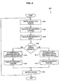
- Process 400 illustrated in FIG. 4 illustrates a second alternative embodiment in accordance with the present invention for providing a flow rate compensated for errors caused by density.
- a density compensation factor may not be applied to the measured flow rate if the density of the material is within a range of densities that do not add unacceptable error to the measured flow rate.
- Process 400 begins in step 401 by receiving signals indicating mass flow rate from sensors affixed to a vibrating conduit. The signals are then used to calculate an uncompensated flow rate in step 402. The flow rate is calculated in a conventional manner well known to those skilled in the art.
- the calculated density is compared to a threshold density in step 404.
- the density may surpass the threshold density by being greater than or less than the threshold density. The comparison used is left to those skilled in the art.
- a density compensation factor is determined in step 405.
- the density compensation factor is determined in the manner described above in step 303 of FIG.3 .
- the density compensation factor is then applied to the uncompensated mass flow rate and a compensated mass flow rate is generated in step 406.
- the uncompensated flow rate may be returned in step 420.
- a density compensation may be determined using a linear compensation in step 411.
- a compensated flow rate is then generated in step 412 by applying the linear density compensation factor to the uncompensated flow rate.
- step 420 the compensated flow rate calculated in step 406 or step 412 is returned and process 400 ends.
Abstract
Description
- This invention relates to the calculation of a mass flow rate of material flowing through a Coriolis flowmeter. More particularly, this invention relates to compensating a measured flow rate for error in the flow rate caused by the density of the material being measured. Still more particularly, this invention relates to determining when the density of a material is causing an unacceptable error in the mass flow rate and compensating for the error caused by density in the flow rate.
- It is known to ruse Coriolis effect mass flowmeters to measure mass flow and other information of materials flowing through a pipeline as disclosed in
U.S. Patent No. 4,491,025 issued to J.E. Smith, et al. of January 1, 1985 andRe. 31,450 to J.E. Smith of February 11, 1982 . These flowmeters have one or more flow tubes of a curved configuration. Each flow tube configuration in a Coriolis mass flowmeter has a set of natural vibration modes, which may be of a simple bending, torsional, radial, or coupled type. Each flow tube is driven to oscillate at resonance in one of these natural modes. The natural vibration modes of the vibrating, material filled systems are defined in part by the combined mass of the flow tubes and the material within the flow tubes. Material flows into the flowmeter from a connected pipeline on the inlet side of the flowmeter. The material is then directed through the flow tube or flow tubes and exits the flowmeter to a pipeline connected on the outlet side. - A driver applies a force to the flow tube. The force causes the flow tube to oscillate. When there is no material flowing through the flowmeter, all points along a flow tube oscillate with an identical phase. As a material begins to flow through the flow tube, Coriolis accelerations cause each point along the flow tube to have a different phase with respect to other points along the flow tube. The phase on the inlet side of the flow tube lags the driver, while the phase on the outlet side leads the driver. Sensors are placed at two different points on the flow tube to produce sinusoidal signals representative of the motion of the flow tube at the two points. A phase difference of the two signals received from the sensors is calculated in units of time.
- The phase difference between the two sensor signals is proportional to the mass flow rate of the material flowing through the flow tube or flow tubes. The mass flow rate of the material is determined by multiplying the phase difference by a flow calibration factor. This flow calibration factor is determined by material properties and cross sectional properties of the flow tube.
- It is a problem that properties of a material may effect mass flow rates measured by Coriolis flowmeters. Some properties of a material that may effect measured flow rates include density, temperature, pressure, and viscosity. In most cases, a Coriolis flowmeter is designed to be insensitive to the errors caused by these properties. In other cases, meter electronics compensate for errors in the measured mass flow rate caused by these properties. For example, meter electronics commonly compensate for errors caused by the temperature and pressure of a material.
- Sometimes the error caused by the properties of a material are insignificant under normal operating conditions and the error in flow rate is not corrected. However, a property of a material may cause unacceptable errors after a certain threshold is surpassed. For example, the density of a material often does not affect the flow rate in most flow meters at most densities. However, in low flow rate Coriolis flowmeters, it has been observed that density of the material effects the measured flow rate of the material after a certain threshold. For purposes of this discussion, low flow rate is 5 lbs./ minute or less. At this time, it is unknown what causes these errors.
- Therefore, it is desirable to determine when the density of the measured material surpasses a threshold and to compensate for the error in flow rate caused by the density.
- The above and other problems are solved and an advance in the art is made by the provision of a method and apparatus for compensating for errors in measured mass flow rates caused by density in a Coriolis flowmeter. One advantage of this invention is that errors in a measured flow rate attributable to density are corrected. A second advantage of this invention is that the compensation is more accurate than other systems as non-linear equations that more precisely fit measured data are used to determine a compensation factor. A third advantage of this invention that the compensation may only occur after the density has surpassed a certain threshold where the error caused by density surpasses an unacceptable level. This reduces the amount of computation needed to provide an accurate flow rate.
- A determination of a mass flow rate that is compensated for density in accordance with this invention is performed in the following manner. First a material flows through a vibrating conduit in a Coriolis flowmeter. The conduit is vibrated and sensors affixed to the conduit generate signals representing the motion of the conduit. Signals from sensors affixed to the vibrating conduit are received by the meter electronics. An uncompensated flow rate of the material is then calculated by the meter electronics from the received signals. A density compensation factor is then determined using uncompensated flow rate and non-linear information relating density to errors in flow rate. A density compensated flow rate is then generated by applying the density compensation factor to the uncompensated flow rate.
- In accordance with this invention, the meter electronics may also calculate a density of the material from the signals received from the sensors. The calculated density then may be compared to a threshold to determine whether the density surpasses a threshold value. If the density does surpass the threshold value the density compensated flow rate is generated. Otherwise the uncompensated flow rate is output.
- In an alternative embodiment, a linear density compensation factor may be calculated using the uncompensated flow rate and linear information relating errors in the mass flow rate to the density of the material if the threshold is not exceeded. The compensated flow rate can be calculated by applying said linear density compensation to said uncompensated mass flow rate.
- In accordance with this invention the density compensation factor may be determined by inserting the uncompensated flow rate into a N order polynomial equation relating density to flow rate error data wherein N is greater than 1. The N order polynomial is a curve fit of density to error rate in measured mass flow. The polynomial may be generated by performing an N order curve fit of the density to flow rate error data wherein N is greater than 1.
- According to one aspect of the present invention, a method for determining a flow rate of a material flowing through a vibrating conduit, the method comprising the steps of:
- receiving signals from sensors affixed to said vibrating conduit;
- calculating an uncompensated flow rate of said material from said signals;
- calculating a density of said material from said signals;
- said method characterized by the steps of:
- determining whether said density surpasses a threshold value;
- responsive to said density surpassing said threshold value,
- determining a density compensation factor from said uncompensated flow rate and information gathered through non-linear data fitting method, relating density to errors in flow rate, and
- calculating a density compensated flow rate by applying said density compensation factor to said uncompensated flow rate; and
- responsive to said density not surpassing said threshold value,
- outputting a flow rate that is not density compensated by said density compensation factor.
- Preferably, said threshold value comprises a density value of 1.030.
- Preferably, the method further comprises the steps of:
- responsive to said density not surpassing said threshold value,
- determining a linear density compensation factor from said uncompensated flow rate and linear information relating errors in flow rate to density; and
- calculating said density compensated flow rate by applying said linear density compensation factor to said uncompensated flow rate.
- Preferably, said step of determining said density compensation factor comprises the step of:
- inserting said uncompensated flow rate into a N order polynomial equation relating density to flow rate error data wherein N is greater than 1.
- Preferably, the method further comprises the step of:
- performing an N order curve fit of said density to flow rate error data wherein N is greater than 1 to determine said N order polynomial equation.
- Preferably, said step of performing said N order curve fit comprises the step of:
- performing a least squares curve fit.
- Preferably, N equals 4.
- Preferably, said step of determining said density compensation factor comprises the step of:
- inserting said uncompensated flow rate and said density into a two dimensional N order polynomial equation relating density to flow rate error data wherein N is greater than 1.
- Preferably, the method further comprises the step of:
- performing a two dimensional N order curve fit of said density and said uncompensated flow rate to determine said N order polynomial.
- Preferably, the step of performing said two dimensional N order curve fit comprises the step of:
- performing a least square curve fit of data for said uncompensated flow rate and said density to determine said two dimensional N order polynomial.
- According to another aspect of the present invention meter electronics for a Coriolis flowmeter having a processing unit that provides a flow rate and comprising:
- instructions for directing said processing unit to:
- receive signals from sensors affixed to a vibrating conduit,
- calculate an uncompensated flow rate of said material from said signals;
- calculate a density of said material from said signals; and
- a media readable by said processing unit that stores said instructions;
- said meter electronics characterized by said instructions directing said processing unit to:
- determine whether said density surpasses a threshold value;
- responsive to said density surpassing said threshold value,
- determine a density compensation factor from said uncompensated flow rate and information gathered through non-linear fitting method, relating density to errors in flow rate, and
- calculate a density compensated flow rate by applying said density compensation factor to said uncompensated flow rate; and
- responsive to said density not surpassing said threshold value,
- output a flow rate that is not density compensated by said density compensation factor.
- Preferably, said threshold value comprises a density value of 1.030.
- Preferably, said instructions further comprise:
- instructions for directing said processing unit to:
- responsive to said density not surpassing said threshold valve,
- determine a linear density compensation factor from said uncompensated flow rate and linear information relating errors in flow rate to density, and
- calculate said density compensated flow rate by applying said linear density compensation factor to said uncompensated flow rate.
- Preferably, said instructions to determine said density compensation factor comprises:
- instructions for directing said processing unit to:
- insert said uncompensated flow rate into a N order polynomial equation relating density to flow rate error data wherein N is greater than 1.
- Preferably, said instructions further comprise:
- instructions for directing said processing unit to:
- perform an N order curve fit of said density to flow rate error data wherein N is greater than 1 to determine said N order polynomial equation.
- Preferably, said instructions to perform said N order curve fit comprises:
- instructions for directing said processing unit to:
- perform a least squares curve fit.
- Preferably, N equals 4.
- Preferably, said instructions to determine said density compensation factor comprise:
- instructions for directing said processing unit to:
- insert said uncompensated flow rate and said density into a two dimensional N order polynomial equation relating density to flow rate error data wherein N is greater than 1.
- Preferably, said instructions further comprise:
- instructions for directing said processing unit to:
- perform a two dimensional N order curve fit of said density and said uncompensated flow rate to determine said N order polynomial.
- Preferably, said instructions to perform said two dimensional N order curve fit comprises:
- instructions for directing said processing unit to:
- perform a least square curve fit of data for said uncompensated flow rate and said density to determine said two dimensional N order polynomial.
- The above and other advantages and aspects of this invention are explained in the detailed description and following drawings:
-
FIG. 1 illustrating a Coriolis flowmeter that incorporates the method and apparatus of this invention; -
FIG. 2 illustrating a chart showing error rates compared to flow rates for varying densities; -
FIG. 3 illustrating a first embodiment of a method for compensating a flow rate for errors caused by density ; -
FIG. 4 illustrating a second embodiment of a method for compensating for errors caused by density in accordance with this invention; and -
FIG. 5 illustrating a processor. - The present invention relates to providing a mass flow rate measurement from a Coriolis flowmeter that compensates for errors in the flow rate caused by the density of a material.
FIG. 1 illustrates an exemplary Coriolis flowmeter that may provide a compensated mass flow rate in accordance with this invention.Coriolis flowmeter 100 includes aflowmeter assembly 110 andmeter electronics 150.Meter electronics 150 are connected tometer assembly 110 vialeads 120 to provide for example, but not limited to, density, mass-flow-rate, volume-flow-rate, and totalized mass-flow rate information over apath 125. A Coriolis flowmeter structure is described although it should be apparent to those skilled in the art that the present invention could be practiced in conjunction with any apparatus having loads requiring currents of alternating voltage. - A Coriolis flowmeter structure is described although it should be apparent to those skilled in the art that the present invention could be practiced in conjunction with any apparatus having a vibrating conduit to measure properties of material flowing through the conduit. A second example of such an apparatus is a vibrating tube densitometerwhich does not have the additional measurement capability provided by Coriolis mass flowmeters.
-
Meter assembly 110 includes a pair offlanges 101 and 101',manifold 102 andconduits Driver 104, pick-offsensors 105 and 105', andtemperature sensor 107 are connected toconduits - When
Coriolis flowmeter 100 is inserted into a pipeline system (not shown) which carries the process material that is being measured, material entersflowmeter assembly 110 throughflange 101, passes throughmanifold 102 where the material is directed to enterconduits conduits manifold 102 from where it exitsmeter assembly 110 through flange 101'. -
Conduits conduits 103A-103B extend outwardly from the manifold in an essentially parallel fashion. -
Conduits 103A-103B are driven bydriver 104 in opposite directions about their respective bending axes W and W' and at what is termed the first out of phase bending mode of the flowmeter.Driver 104 may comprise any one of many well known arrangements, such as a magnet mounted toconduit 103A and an opposing coil mounted toconduit 103B and through which an alternating current is passed for vibrating both conduits. A suitable drive signal is applied bymeter electronics 150 todriver 104 viapath 112. - Pick-off
sensors 105 and 105' are affixed to at least one ofconduits conduit 103A-103B vibrates, pick-off sensors 105-105' generate a first pick-off signal and a second pick-off signal. The first and second pick-off signals are applied topaths 111 and 111'. The driver velocity signal is applied topath 112. -
Temperature sensor 107 is affixed to at least oneconduit 103A and/or 103B.Temperature sensor 107 measures the temperature of the conduit in order to modify equations for the temperature of the system.Path 111" carries temperature signals fromtemperature sensor 107 tometer electronics 150. -
Meter electronics 150 receives the first and second pick-off signals appearing onpaths 111 and 111', respectively.Meter electronics 150 processes the first and second velocity signals to compute the mass flow rate, the density, or other property of the material passing throughflowmeter assembly 110. This computed information is applied bymeter electronics 150 overpath 125 to a utilization means (not shown). It is known to those skilled in the art thatCoriolis flowmeter 100 is quite similar in structure to a vibrating tube densitometer. Vibrating tube densitometers also utilize a vibrating tube through which fluid flows or, in the case of a sample-type densitometer, within which fluid is held. Vibrating tube densitometers also employ a drive system for exciting the conduit to vibrate. Vibrating tube densitometers typically utilize only single feedback signal since a density measurement requires only the measurement of frequency and a phase measurement is not necessary. The descriptions of the present invention herein apply equally to vibrating tube densitometers. - In
Coriolis flowmeter 100, themeter electronics 150 are physically divided into 2 components ahost system 170 and asignal conditioner 160. In conventional meter electronics, these components are housed in one unit. -
Signal conditioner 160 includesdrive circuitry 163 and sensorsignal conditioning circuitry 161. One skilled in the art will recognize that inactuality drive circuitry 163 and pick-offconditioning circuitry 161 may be separate analog circuits or may be separate functions provided by a digital signal processor or other digital components.Drive circuitry 163 generates a drive signal and applies an alternating drive current todriver 104 viapath 112 ofpath 120. The circuitry of the present invention may be included indrive circuitry 163 to provide an alternating current todriver 104. - In actuality,
path 112 is a first and a second lead.Drive circuitry 163 is communicatively connected to sensorsignal conditioning circuitry 161 viapath 162.Path 162 allows drive circuitry to monitor the incoming pick-off signals to adjust the drive signal. Power to operatedrive circuitry 163 and sensorsignal conditioning circuitry 161 is supplied fromhost system 170 via afirst wire 173 and asecond wire 174.First wire 173 andsecond wire 174 may be a part of a conventional 2-wire, 4-wire cable, or a portion of a multi-pair cable. - Sensor
signal conditioning circuitry 161 receives input signals from first pick-off 105, second pick-off 105', andtemperature sensor 107 viapaths signal conditioning circuitry 161 determines the frequency of the pick-off signals and may also determine properties of a material flowing throughconduits 103A-103B. After the frequency of the input signals from pick-off sensors 105-105' and properties of the material are determined, parameter signals carrying this information are generated and transmitted to asecondary processing unit 171 inhost system 170 viapath 176. In a preferred embodiment,path 176 includes 2 leads. However, one skilled in the art will recognize thatpath 176 may be carried overfirst wire 173 andsecond wire 174 or over any other number of wires. -
Host system 170 includes apower supply 172 andsecondary processing unit 171.Power supply 172 receives electricity from a source and converts the received electricity to the proper power needed by the system.Secondary processing unit 171 receives the parameter signals from pick-offsignal conditioning circuitry 161 and then may perform processes needed to provide properties of the material flowing throughconduits 103A-103B needed by a user. Such properties may include but are not limited to density, mass flow rate, and volumetric flow rate. - The following invention is implemented by a processing unit. Either a digital signal processor in
signal conditioner 160 orsecondary processing unit 171 may implement the present invention.FIG. 5 illustrates a conventional processing unit that is operative to implement this invention. -
Processing system 500 includes a Central Processing Unit (CPU) 501.CPU 501 is a processor, microprocessor, or combination of processor and/or microprocessor which execute instructions that are stored in memory.Memory bus 502 connectsCPU 501 to memory needed to execute instructions. Non-volatile memory such as Read Only Memory (ROM) 510 is connected tomemory bus 502 viapath 511.ROM 510 stores configuration instructions and other instructions needed to properly operateprocessing system 500. A volatile memory, suchRandom Access Memory 520, is connected tomemory bus 502 viapath 521.RAM 520 stores instructions and data needed to perform applications executed byCPU 501. - Input/ Output (I/O)
bus 503 connectsCPU 501 to other devices needed to execute instructions. Analog to Digital (A/D)convertor 530 allowCPU 501 to receive signals from analog circuitry such as pick-off sensors 105-105' ofFIG. 1 . A/D convertor 530 is connected to I/O bus 503 and receives analog signals from other circuitry (Not Shown) viapath 532.Peripheral device 540 is another device that performs a required function forprocessing system 500 to provide data toCPU 501.Peripheral device 540 is connected to I/O bus 503 viapath 541.Memory 550 is a device that provides extra data storage capability toprocessing system 500, such as a disk drive and disk.Memory 550 is connected to I/O bus 503 viapath 551. - It is a problem that the mass flow measurement provided by a Coriolis flowmeter such as
Coriolis flowmeter 100 may be affected by properties of the measured material. One such property is density of the material. Small Coriolis flowmeters are particularly susceptible to errors caused by the density of the measured material. For purposes of this discussion a small Coriolis flowmeter is a flowmeter that has flow tubes with a diameter of .33 cm (.130 inches). An example of such a flowmeter, is the CMF 010 Coriolis Flowmeter produced by Micro Motion INC. of Boulder, Colorado. -
FIG. 2 is an illustration of a plotting of error in flow rates of materials having varying densities.Line 201 represents error in uncompensated flow rates as the flow rate changes for a material having a density .9957.Line 202 represents the error in uncompensated flow rates as flow rates change for materials having a density of .9489.Line 203 represents the error in uncompensated flow rates for material having a density of .85284.Line 204 represents error rates of uncompensated flow rates for a material having a density of .78922.Line 205 represents the error in uncompensated flow rates for materials having a density of .90452. - As can be seen from
FIG. 2 , material having densities proximate to 1.0 cause less percentage error. While densities that are not proximate 1.0 tend to have a percentage of error that is greater than .1 %. - From the graph of
FIG. 2 , one skilled in the art can see that densities that are not proximate to 1 cause a small flowmeter to provide inaccurate flow rates. The present invention corrects the flow rate by multiplying the measured flow rate by a density compensation factor. - The density compensation factor may be calculated in any of the following manners: a look up for compensation factors based upon uncompensated flow rates, comparing density to a least squared polynomial fit of uncompensated density, or a two dimensional least square curve fit of uncompensated density and mass flow rate. One skilled in the art will recognize that other data fitting methods may be used to determine the density compensation factor.
- The relationship between density and flow rate can then be used to compensate the flow rate for errors caused by density.
FIGS. 3 and4 illustrate alternative processes for providing a flow rate having a density compensation . The process illustrated inFIGS. 3 and4 are executed bymeter electronics 150 or by a secondary processing unit which receives data frommeter electronics 150.Process 300 illustrated inFIG. 3 is a first alternative embodiment . Inprocess 300, every flow rate measurement is compensated for density in the following manner. -
Process 300 begins instep 301 with signals indicating mass flow rate being received from the sensors affixed to the vibrating conduit. One skilled in the art will recognize that these signals may be the analog signals received directly from the pick-off sensors or the signals may be digital signals representing the phase difference between signals from the sensor. This is a design choice and varies depending on the type of circuitry used to perform the process. - In
step 302, an uncompensated flow rate is calculated. The flow rate is calculated in a conventional manner well known in the art and a description of flow rate calculation is omitted for brevity and clarity. - A density compensation factor is then determined in
step 303. The density compensation factor may be determined in many different manners. A first solution would be to maintain a memory that stores a flow rate and associated compensation factor or compensated flow rate. A simple look-up could then be performed to determine the compensation factor or compensated flow rate. - A prior art method for determining a compensation factor is a linear or first order curve fit of data. The uncompensated flow rate is inserted into the equation and a proper density compensation factor is determined.
- However, a first order curve fit does not provide an accurate representation of the data. Therefore, it is preferable to generate an N order polynomial equation that better fits gathered data to represent the compensation factor. The uncompensated flow rate is then inserted into the equation to solve for the density compensation factor. In a preferred embodiment, it is determined that a 4th order polynomial best fits the data and therefore the fourth order equation is used. However, one skilled in the art will recognize that other ordered equations may be used based upon the accuracy of the results.
- In the preferred embodiment, it is determined that the following 4th order equation best fits the data.

- a 0 = +.9983;
- a 1 = +.0052;
- a 2 = +.0094;
- a 3 = +.0051;
- a 4 = -.0008; and
- m = uncompensated flow rate
- A second method for determining a compensation factor is accomplished using a two dimension curve fit to a N order polynomial. A two dimensional curve fit is a curve fit for two variables of data. In this case, the curve fit is for mass flow represented by m and density represented by d. In a preferred embodiment, a least square fit of density and mass flow rate to the compensation factor. Through experimentation of fitting data to various polynomials, it has been determined that a fourth order polynomial fit of density and mass flow rate to the compensation factor as shown in the following equation:

- a 1,a 2,a 3,a 4,a 5,a 6,a 7,a 8,a 9 = coefficients;
- m= mass flow rate; and
- d= density
- After the density compensation factor is determined in
step 303, the density compensation factor is applied to the uncompensated mass flow rate to generate a density compensated mass flow rate instep 304 andprocess 300 ends. -
Process 400 illustrated inFIG. 4 illustrates a second alternative embodiment in accordance with the present invention for providing a flow rate compensated for errors caused by density. In this embodiment, a density compensation factor may not be applied to the measured flow rate if the density of the material is within a range of densities that do not add unacceptable error to the measured flow rate. -
Process 400 begins instep 401 by receiving signals indicating mass flow rate from sensors affixed to a vibrating conduit. The signals are then used to calculate an uncompensated flow rate instep 402. The flow rate is calculated in a conventional manner well known to those skilled in the art. - In
step 403, a density of the material is calculated from the signals from a conventional or well known equation such as:
- p = density of material
- p1 = density of a first known material such as water;
- p2 = density of a second known material such as air;
- K1 = constant of the first known material such as water;
- K2 = constant of the second known material such as air; and
- τ = rate of oscillation of the flow tube.
- After the density is calculated, the calculated density is compared to a threshold density in
step 404. The density may surpass the threshold density by being greater than or less than the threshold density. The comparison used is left to those skilled in the art. - If the calculated density surpasses the threshold density, a density compensation factor is determined in
step 405. The density compensation factor is determined in the manner described above instep 303 ofFIG.3 . The density compensation factor is then applied to the uncompensated mass flow rate and a compensated mass flow rate is generated instep 406. - If the calculated density does not surpass a threshold density, the uncompensated flow rate may be returned in
step 420. Alternatively, since it is known that a linear density compensation may be sufficient, a density compensation may be determined using a linear compensation instep 411. A compensated flow rate is then generated instep 412 by applying the linear density compensation factor to the uncompensated flow rate. - In
step 420, the compensated flow rate calculated instep 406 or step 412 is returned andprocess 400 ends.
Claims (20)
- A method (300) for determining a flow rate of a material flowing through a vibrating conduit (103A, 103B), the method comprising the steps of:receiving (301) signals from sensors (105, 105') affixed to said vibrating conduit;calculating (302) an uncompensated flow rate of said material from said signals;calculating a density of said material from said signals;said method characterized by the steps of:determining whether said density surpasses a threshold value;responsive to said density surpassing said threshold value,
determining (303) a density compensation factor from said uncompensated flow rate and information gathered through non-linear data fitting method, relating density to errors in flow rate, and
calculating (304) a density compensated flow rate by applying said density compensation factor to said uncompensated flow rate; andresponsive to said density not surpassing said threshold value,
outputting a flow rate that is not density compensated by said density compensation factor. - The method (300) of claim 1 wherein said threshold value comprises a density value of 1.030.
- The method (300) of claim 1 further comprising the steps of:responsive to said density not surpassing said threshold value,
determining (411) a linear density compensation factor from said uncompensated flow rate and linear information relating errors in flow rate to density; and
calculating (412) said density compensated flow rate by applying said linear density compensation factor to said uncompensated flow rate. - The method (300) of claim 1 wherein said step of determining said density compensation factor comprises the step of:inserting said uncompensated flow rate into a N order polynomial equation relating density to flow rate error data wherein N is greater than 1.
- The method (300) of claim 4 further comprising the step of:performing an N order curve fit of said density to flow rate error data wherein N is greater than 1 to determine said N order polynomial equation.
- The method (300) of claim 5 wherein said step of performing said N order curve fit comprises the step of:performing a least squares curve fit.
- The method (300) of claim 4 wherein N equals 4.
- The method (300) of claim 1 wherein said step of determining said density compensation factor comprises the step of:inserting said uncompensated flow rate and said density into a two dimensional N order polynomial equation relating density to flow rate error data wherein N is greater than 1.
- The method (300) of claim 8 further comprising the step of:performing a two dimensional N order curve fit of said density and said uncompensated flow rate to determine said N order polynomial.
- The method (300) of claim 9 wherein said step of performing said two dimensional N order curve fit comprises the step of:performing a least square curve fit of data for said uncompensated flow rate and said density to determine said two dimensional N order polynomial.
- Meter electronics (150) for a Coriolis flowmeter (110) having a processing unit that (500) provides a flow rate and comprising:instructions for directing said processing unit to:receive signals from sensors (105, 105') affixed to a vibrating conduit (103A, 103B),calculate an uncompensated flow rate of said material from said signals;calculate a density of said material from said signals; anda media readable (550) by said processing unit that stores said instructions;said meter electronics characterized by said instructions directing said processing unit to:determine whether said density surpasses a threshold value;responsive to said density surpassing said threshold value,
determine a density compensation factor from said uncompensated flow rate and information gathered through non-linear data fitting method, relating density to errors in flow rate, and
calculate a density compensated flow rate by applying said density compensation factor to said uncompensated flow rate; andresponsive to said density not surpassing said threshold value,
output a flow rate that is not density compensated by said density compensation factor. - The meter electronics (150) of claim 11 wherein said threshold value comprises a density value of 1.030.
- The meter electronics (150) of claim 11 wherein said instructions further comprise:instructions for directing said processing unit (500) to:responsive to said density not surpassing said threshold value,
determine a linear density compensation factor from said uncompensated flow rate and linear information relating errors in flow rate to density, and
calculate said density compensated flow rate by applying said linear density compensation factor to said uncompensated flow rate. - The meter electronics (150) of claim 11 wherein said instructions to determine said density compensation factor comprises:instructions for directing said processing unit (500) to:insert said uncompensated flow rate into a N order polynomial equation relating density to flow rate error data wherein N is greater than 1.
- The meter electronics (150) of claim 14 wherein said instructions further comprise:instructions for directing said processing unit (500) to:perform an N order curve fit of said density to flow rate error data wherein N is greater than 1 to determine said N order polynomial equation.
- The meter electronics (150) of claim 15 wherein said instructions to perform said N order curve fit comprises:instructions for directing said processing unit (500) to:perform a least squares curve fit.
- The meter electronics (150) of claim 14 wherein N equals 4.
- The meter electronics (150) of claim 11 wherein said instructions to determine said density compensation factor comprise:instructions for directing said processing unit (500) to:insert said uncompensated flow rate and said density into a two dimensional N order polynomial equation relating density to flow rate error data wherein N is greater than 1.
- The meter electronics (150) of claim 18 wherein said instructions further comprise:instructions for directing said processing unit (500) to:perform a two dimensional N order curve fit of said density and said uncompensated flow rate to determine said N order polynomial.
- The meter electronics (150) of claim 19 wherein said instructions to perform said two dimensional N order curve fit comprises:instructions for directing said processing unit (500) to:perform a least square curve fit of data for said uncompensated flow rate and said density to determine said two dimensional N order polynomial.
Applications Claiming Priority (3)
| Application Number | Priority Date | Filing Date | Title |
|---|---|---|---|
| US705995 | 1991-05-28 | ||
| US09/705,995 US6556931B1 (en) | 2000-11-03 | 2000-11-03 | Apparatus and method for compensating mass flow rate of a material when the density of the material causes an unacceptable error in flow rate |
| PCT/US2001/047609 WO2002037063A2 (en) | 2000-11-03 | 2001-10-26 | Apparatus and method for compensating mass flow rate of a material when the density of the material causes an unacceptable error in flow rate |
Publications (2)
| Publication Number | Publication Date |
|---|---|
| EP1334334A2 EP1334334A2 (en) | 2003-08-13 |
| EP1334334B1 true EP1334334B1 (en) | 2012-05-30 |
Family
ID=24835779
Family Applications (1)
| Application Number | Title | Priority Date | Filing Date |
|---|---|---|---|
| EP01990076A Expired - Lifetime EP1334334B1 (en) | 2000-11-03 | 2001-10-26 | Apparatus and method for compensating mass flow rate of a material when the density of the material causes an unacceptable error in flow rate |
Country Status (16)
| Country | Link |
|---|---|
| US (1) | US6556931B1 (en) |
| EP (1) | EP1334334B1 (en) |
| JP (1) | JP4588293B2 (en) |
| KR (1) | KR100606207B1 (en) |
| CN (1) | CN1227514C (en) |
| AR (1) | AR031030A1 (en) |
| AU (2) | AU2894702A (en) |
| BR (1) | BR0114951B1 (en) |
| CA (1) | CA2424348C (en) |
| DK (1) | DK1334334T3 (en) |
| HK (1) | HK1061066A1 (en) |
| MX (1) | MXPA03003862A (en) |
| MY (1) | MY126832A (en) |
| PL (1) | PL199791B1 (en) |
| RU (1) | RU2265191C2 (en) |
| WO (1) | WO2002037063A2 (en) |
Families Citing this family (25)
| Publication number | Priority date | Publication date | Assignee | Title |
|---|---|---|---|---|
| US7040181B2 (en) | 2004-03-19 | 2006-05-09 | Endress + Hauser Flowtec Ag | Coriolis mass measuring device |
| US7284449B2 (en) | 2004-03-19 | 2007-10-23 | Endress + Hauser Flowtec Ag | In-line measuring device |
| DE102004018326B4 (en) | 2004-04-13 | 2023-02-23 | Endress + Hauser Flowtec Ag | Device and method for measuring a density and/or a viscosity of a fluid |
| EP1759177B1 (en) * | 2004-06-22 | 2022-02-23 | Micro Motion, Inc. | Meter electronics and method for detecting a residual material in a flow meter assembly |
| DE102005046319A1 (en) | 2005-09-27 | 2007-03-29 | Endress + Hauser Flowtec Ag | Two or multi-phase medium e.g. fluid`s, physical flow parameter e.g. flow rate, measuring method, involves producing measurement values representing parameter by considering pressure difference of medium and by usage of transfer function |
| US7360452B2 (en) * | 2005-12-27 | 2008-04-22 | Endress + Hauser Flowtec Ag | In-line measuring devices and method for compensation measurement errors in in-line measuring devices |
| US7360453B2 (en) * | 2005-12-27 | 2008-04-22 | Endress + Hauser Flowtec Ag | In-line measuring devices and method for compensation measurement errors in in-line measuring devices |
| CN101336364B (en) | 2005-12-27 | 2011-04-13 | 恩德斯+豪斯流量技术股份有限公司 | In-line measuring devices and method for compensating measurement errors in in-line measuring devices |
| US7280927B1 (en) * | 2006-10-11 | 2007-10-09 | Honeywell International Inc. | Method and system for providing a linear signal from a mass airflow and/or liquid flow transducer |
| DE102006062600B4 (en) | 2006-12-29 | 2023-12-21 | Endress + Hauser Flowtec Ag | Method for commissioning and/or monitoring an in-line measuring device |
| AU2007352590B2 (en) * | 2007-05-03 | 2011-03-17 | Micro Motion, Inc. | Vibratory flow meter and method for correcting for an entrained phase in a two-phase flow of a flow material |
| DE102008016235A1 (en) | 2008-03-27 | 2009-10-01 | Endress + Hauser Flowtec Ag | A method of operating a meter disposed on a rotary carousel filling machine |
| DE102008050113A1 (en) | 2008-10-06 | 2010-04-08 | Endress + Hauser Flowtec Ag | In-line measuring device |
| DE102008050115A1 (en) | 2008-10-06 | 2010-04-08 | Endress + Hauser Flowtec Ag | In-line measuring device |
| DE102008050116A1 (en) | 2008-10-06 | 2010-04-08 | Endress + Hauser Flowtec Ag | In-line measuring device |
| JP5307292B2 (en) * | 2009-05-27 | 2013-10-02 | マイクロ モーション インコーポレイテッド | Method and apparatus for determining flow rate error of vibratory flow meter |
| MX360511B (en) | 2014-10-21 | 2018-11-07 | Micro Motion Inc | Apparatus for applying a variable zero algorithm in a vibrating flowmeter and related method. |
| CA2982732C (en) * | 2015-04-14 | 2020-03-10 | Micro Motion, Inc. | Detecting an inaccurate flow rate measurement by a vibratory meter |
| MX2020009297A (en) | 2018-04-02 | 2020-09-28 | Micro Motion Inc | Method of compensating for mass flow using known density. |
| CN108955837B (en) * | 2018-07-20 | 2020-02-28 | 浙江中衡商品检验有限公司 | Method for determining online system error of mass flowmeter and application thereof |
| EP3899456B1 (en) * | 2018-12-17 | 2023-10-11 | Micro Motion, Inc. | Converting a directly measured mass flow rate to account for buoyancy |
| KR102160408B1 (en) * | 2019-04-15 | 2020-10-05 | 한국생산기술연구원 | Volumetric water wheel |
| DE102019126883A1 (en) * | 2019-10-07 | 2021-04-08 | Endress+Hauser Flowtec Ag | Method for monitoring a measuring device system |
| DE102021131866A1 (en) | 2021-12-03 | 2023-06-07 | Endress+Hauser Flowtec Ag | Method for detecting a foreign body in a medium |
| CN116148754B (en) * | 2023-04-18 | 2023-06-27 | 石家庄科林电气股份有限公司 | Electric energy meter adjusting method and device and electronic equipment |
Family Cites Families (8)
| Publication number | Priority date | Publication date | Assignee | Title |
|---|---|---|---|---|
| USRE31450E (en) | 1977-07-25 | 1983-11-29 | Micro Motion, Inc. | Method and structure for flow measurement |
| US4491025A (en) | 1982-11-03 | 1985-01-01 | Micro Motion, Inc. | Parallel path Coriolis mass flow rate meter |
| US5497665A (en) | 1991-02-05 | 1996-03-12 | Direct Measurement Corporation | Coriolis mass flow rate meter having adjustable pressure and density sensitivity |
| US5448921A (en) | 1991-02-05 | 1995-09-12 | Direct Measurement Corporation | Coriolis mass flow rate meter |
| US5827979A (en) | 1996-04-22 | 1998-10-27 | Direct Measurement Corporation | Signal processing apparati and methods for attenuating shifts in zero intercept attributable to a changing boundary condition in a Coriolis mass flow meter |
| US5687100A (en) * | 1996-07-16 | 1997-11-11 | Micro Motion, Inc. | Vibrating tube densimeter |
| US6092409A (en) | 1998-01-29 | 2000-07-25 | Micro Motion, Inc. | System for validating calibration of a coriolis flowmeter |
| US6367336B1 (en) * | 1998-12-29 | 2002-04-09 | Hugo Gabriel Martina | Process mass flow apparatus and method for measuring the mass flow of powdered and granulated solids as well as the accumulated weight of material passed during a specified time |
-
2000
- 2000-11-03 US US09/705,995 patent/US6556931B1/en not_active Expired - Lifetime
-
2001
- 2001-10-16 MY MYPI20014800A patent/MY126832A/en unknown
- 2001-10-22 AR ARP010104940A patent/AR031030A1/en active IP Right Grant
- 2001-10-26 MX MXPA03003862A patent/MXPA03003862A/en active IP Right Grant
- 2001-10-26 BR BRPI0114951-2B1A patent/BR0114951B1/en active IP Right Grant
- 2001-10-26 AU AU2894702A patent/AU2894702A/en active Pending
- 2001-10-26 AU AU2002228947A patent/AU2002228947B2/en not_active Ceased
- 2001-10-26 JP JP2002539773A patent/JP4588293B2/en not_active Expired - Lifetime
- 2001-10-26 EP EP01990076A patent/EP1334334B1/en not_active Expired - Lifetime
- 2001-10-26 CA CA002424348A patent/CA2424348C/en not_active Expired - Lifetime
- 2001-10-26 WO PCT/US2001/047609 patent/WO2002037063A2/en active IP Right Grant
- 2001-10-26 DK DK01990076.0T patent/DK1334334T3/en active
- 2001-10-26 RU RU2003116240/28A patent/RU2265191C2/en active
- 2001-10-26 PL PL360994A patent/PL199791B1/en unknown
- 2001-10-26 CN CNB018182607A patent/CN1227514C/en not_active Expired - Fee Related
- 2001-10-26 KR KR1020037006163A patent/KR100606207B1/en active IP Right Grant
-
2004
- 2004-06-08 HK HK04104078A patent/HK1061066A1/en not_active IP Right Cessation
Also Published As
| Publication number | Publication date |
|---|---|
| CN1227514C (en) | 2005-11-16 |
| KR100606207B1 (en) | 2006-07-28 |
| JP4588293B2 (en) | 2010-11-24 |
| AU2002228947B2 (en) | 2005-05-12 |
| MY126832A (en) | 2006-10-31 |
| KR20030048113A (en) | 2003-06-18 |
| US6556931B1 (en) | 2003-04-29 |
| BR0114951A (en) | 2003-11-04 |
| CA2424348A1 (en) | 2002-05-10 |
| CA2424348C (en) | 2007-10-09 |
| EP1334334A2 (en) | 2003-08-13 |
| PL360994A1 (en) | 2004-09-20 |
| AR031030A1 (en) | 2003-09-03 |
| DK1334334T3 (en) | 2012-08-13 |
| BR0114951B1 (en) | 2013-09-03 |
| PL199791B1 (en) | 2008-10-31 |
| AU2894702A (en) | 2002-05-15 |
| MXPA03003862A (en) | 2004-04-20 |
| CN1473262A (en) | 2004-02-04 |
| RU2265191C2 (en) | 2005-11-27 |
| WO2002037063A8 (en) | 2002-08-01 |
| WO2002037063A3 (en) | 2003-03-20 |
| HK1061066A1 (en) | 2004-09-03 |
| JP2004521319A (en) | 2004-07-15 |
| WO2002037063A2 (en) | 2002-05-10 |
Similar Documents
| Publication | Publication Date | Title |
|---|---|---|
| EP1334334B1 (en) | Apparatus and method for compensating mass flow rate of a material when the density of the material causes an unacceptable error in flow rate | |
| EP1421346B1 (en) | A majority component proportion determination of a fluid using a coriolis flowmeter | |
| AU2002228947A1 (en) | Apparatus and method for compensating mass flow rate of a material when the density of the material causes an unacceptable error in flow rate | |
| EP0690981B1 (en) | Vibrating tube densimeter | |
| EP1051597B1 (en) | System for validating calibration of a coriolis flowmeter | |
| EP0912882B9 (en) | Vibrating tube densimeter | |
| EP1301761B1 (en) | A system for calibrating a drive signal in a coriolis flowmeter | |
| US20130121376A1 (en) | Method and apparatus for determining a temperature of a vibrating sensor component of a vibrating meter | |
| EP2435801B1 (en) | Method and apparatus for determining a flow rate error in a vibrating flow meter | |
| AU2002323396A1 (en) | A majority component proportion determination of a fluid using a coriolis flowmeter | |
| JP2004521319A5 (en) | ||
| EP1798536B1 (en) | Temperature measurement with a Coriolis flow meter | |
| WO2001001084A1 (en) | Type identification for drive control of a coriolis flowmeter | |
| EP1285238B1 (en) | Method and apparatus to control power drawn by a measurement device | |
| EP1668322B1 (en) | Method for detecting corrosion, erosion or product buildup on vibrating element densitometers and coriolis flowmeters and calibration validation |
Legal Events
| Date | Code | Title | Description |
|---|---|---|---|
| PUAI | Public reference made under article 153(3) epc to a published international application that has entered the european phase |
Free format text: ORIGINAL CODE: 0009012 |
|
| 17P | Request for examination filed |
Effective date: 20030502 |
|
| AK | Designated contracting states |
Designated state(s): AT BE CH CY DE DK ES FI FR GB GR IE IT LI LU MC NL PT SE TR |
|
| AX | Request for extension of the european patent |
Extension state: AL LT LV MK RO SI |
|
| 17Q | First examination report despatched |
Effective date: 20071228 |
|
| REG | Reference to a national code |
Ref country code: DE Ref legal event code: R079 Ref document number: 60146640 Country of ref document: DE Free format text: PREVIOUS MAIN CLASS: G01F0001000000 Ipc: G01F0015020000 |
|
| GRAP | Despatch of communication of intention to grant a patent |
Free format text: ORIGINAL CODE: EPIDOSNIGR1 |
|
| RIC1 | Information provided on ipc code assigned before grant |
Ipc: G01F 15/02 20060101AFI20111118BHEP Ipc: G01F 1/84 20060101ALI20111118BHEP |
|
| GRAS | Grant fee paid |
Free format text: ORIGINAL CODE: EPIDOSNIGR3 |
|
| GRAA | (expected) grant |
Free format text: ORIGINAL CODE: 0009210 |
|
| AK | Designated contracting states |
Kind code of ref document: B1 Designated state(s): AT BE CH CY DE DK ES FI FR GB GR IE IT LI LU MC NL PT SE TR |
|
| REG | Reference to a national code |
Ref country code: GB Ref legal event code: FG4D |
|
| REG | Reference to a national code |
Ref country code: CH Ref legal event code: EP |
|
| REG | Reference to a national code |
Ref country code: AT Ref legal event code: REF Ref document number: 560271 Country of ref document: AT Kind code of ref document: T Effective date: 20120615 |
|
| REG | Reference to a national code |
Ref country code: IE Ref legal event code: FG4D |
|
| REG | Reference to a national code |
Ref country code: DE Ref legal event code: R096 Ref document number: 60146640 Country of ref document: DE Effective date: 20120726 |
|
| REG | Reference to a national code |
Ref country code: DK Ref legal event code: T3 |
|
| REG | Reference to a national code |
Ref country code: CH Ref legal event code: NV Representative=s name: VOSSIUS & PARTNER |
|
| REG | Reference to a national code |
Ref country code: NL Ref legal event code: T3 |
|
| PG25 | Lapsed in a contracting state [announced via postgrant information from national office to epo] |
Ref country code: FI Free format text: LAPSE BECAUSE OF FAILURE TO SUBMIT A TRANSLATION OF THE DESCRIPTION OR TO PAY THE FEE WITHIN THE PRESCRIBED TIME-LIMIT Effective date: 20120530 Ref country code: SE Free format text: LAPSE BECAUSE OF FAILURE TO SUBMIT A TRANSLATION OF THE DESCRIPTION OR TO PAY THE FEE WITHIN THE PRESCRIBED TIME-LIMIT Effective date: 20120530 Ref country code: CY Free format text: LAPSE BECAUSE OF FAILURE TO SUBMIT A TRANSLATION OF THE DESCRIPTION OR TO PAY THE FEE WITHIN THE PRESCRIBED TIME-LIMIT Effective date: 20120530 |
|
| REG | Reference to a national code |
Ref country code: AT Ref legal event code: MK05 Ref document number: 560271 Country of ref document: AT Kind code of ref document: T Effective date: 20120530 |
|
| PG25 | Lapsed in a contracting state [announced via postgrant information from national office to epo] |
Ref country code: GR Free format text: LAPSE BECAUSE OF FAILURE TO SUBMIT A TRANSLATION OF THE DESCRIPTION OR TO PAY THE FEE WITHIN THE PRESCRIBED TIME-LIMIT Effective date: 20120831 |
|
| PG25 | Lapsed in a contracting state [announced via postgrant information from national office to epo] |
Ref country code: BE Free format text: LAPSE BECAUSE OF FAILURE TO SUBMIT A TRANSLATION OF THE DESCRIPTION OR TO PAY THE FEE WITHIN THE PRESCRIBED TIME-LIMIT Effective date: 20120530 |
|
| PG25 | Lapsed in a contracting state [announced via postgrant information from national office to epo] |
Ref country code: AT Free format text: LAPSE BECAUSE OF FAILURE TO SUBMIT A TRANSLATION OF THE DESCRIPTION OR TO PAY THE FEE WITHIN THE PRESCRIBED TIME-LIMIT Effective date: 20120530 |
|
| PG25 | Lapsed in a contracting state [announced via postgrant information from national office to epo] |
Ref country code: PT Free format text: LAPSE BECAUSE OF FAILURE TO SUBMIT A TRANSLATION OF THE DESCRIPTION OR TO PAY THE FEE WITHIN THE PRESCRIBED TIME-LIMIT Effective date: 20121001 |
|
| PLBE | No opposition filed within time limit |
Free format text: ORIGINAL CODE: 0009261 |
|
| STAA | Information on the status of an ep patent application or granted ep patent |
Free format text: STATUS: NO OPPOSITION FILED WITHIN TIME LIMIT |
|
| PG25 | Lapsed in a contracting state [announced via postgrant information from national office to epo] |
Ref country code: ES Free format text: LAPSE BECAUSE OF FAILURE TO SUBMIT A TRANSLATION OF THE DESCRIPTION OR TO PAY THE FEE WITHIN THE PRESCRIBED TIME-LIMIT Effective date: 20120910 |
|
| 26N | No opposition filed |
Effective date: 20130301 |
|
| PG25 | Lapsed in a contracting state [announced via postgrant information from national office to epo] |
Ref country code: MC Free format text: LAPSE BECAUSE OF NON-PAYMENT OF DUE FEES Effective date: 20121031 |
|
| REG | Reference to a national code |
Ref country code: DE Ref legal event code: R097 Ref document number: 60146640 Country of ref document: DE Effective date: 20130301 |
|
| REG | Reference to a national code |
Ref country code: IE Ref legal event code: MM4A |
|
| PG25 | Lapsed in a contracting state [announced via postgrant information from national office to epo] |
Ref country code: IE Free format text: LAPSE BECAUSE OF NON-PAYMENT OF DUE FEES Effective date: 20121026 |
|
| PG25 | Lapsed in a contracting state [announced via postgrant information from national office to epo] |
Ref country code: TR Free format text: LAPSE BECAUSE OF FAILURE TO SUBMIT A TRANSLATION OF THE DESCRIPTION OR TO PAY THE FEE WITHIN THE PRESCRIBED TIME-LIMIT Effective date: 20120530 |
|
| PG25 | Lapsed in a contracting state [announced via postgrant information from national office to epo] |
Ref country code: LU Free format text: LAPSE BECAUSE OF NON-PAYMENT OF DUE FEES Effective date: 20121026 |
|
| PGFP | Annual fee paid to national office [announced via postgrant information from national office to epo] |
Ref country code: DK Payment date: 20141027 Year of fee payment: 14 |
|
| REG | Reference to a national code |
Ref country code: FR Ref legal event code: PLFP Year of fee payment: 15 |
|
| REG | Reference to a national code |
Ref country code: DK Ref legal event code: EBP Effective date: 20151031 |
|
| REG | Reference to a national code |
Ref country code: CH Ref legal event code: PFA Owner name: MICRO MOTION, INC., US Free format text: FORMER OWNER: MICRO MOTION, INC., US |
|
| REG | Reference to a national code |
Ref country code: FR Ref legal event code: PLFP Year of fee payment: 16 |
|
| PG25 | Lapsed in a contracting state [announced via postgrant information from national office to epo] |
Ref country code: DK Free format text: LAPSE BECAUSE OF NON-PAYMENT OF DUE FEES Effective date: 20151031 |
|
| REG | Reference to a national code |
Ref country code: FR Ref legal event code: PLFP Year of fee payment: 17 |
|
| REG | Reference to a national code |
Ref country code: FR Ref legal event code: PLFP Year of fee payment: 18 |
|
| PGFP | Annual fee paid to national office [announced via postgrant information from national office to epo] |
Ref country code: DE Payment date: 20191029 Year of fee payment: 19 Ref country code: NL Payment date: 20191026 Year of fee payment: 19 |
|
| PGFP | Annual fee paid to national office [announced via postgrant information from national office to epo] |
Ref country code: FR Payment date: 20191025 Year of fee payment: 19 Ref country code: IT Payment date: 20191023 Year of fee payment: 19 |
|
| PGFP | Annual fee paid to national office [announced via postgrant information from national office to epo] |
Ref country code: CH Payment date: 20191104 Year of fee payment: 19 |
|
| PGFP | Annual fee paid to national office [announced via postgrant information from national office to epo] |
Ref country code: GB Payment date: 20191028 Year of fee payment: 19 |
|
| REG | Reference to a national code |
Ref country code: DE Ref legal event code: R119 Ref document number: 60146640 Country of ref document: DE |
|
| REG | Reference to a national code |
Ref country code: CH Ref legal event code: PL |
|
| REG | Reference to a national code |
Ref country code: NL Ref legal event code: MM Effective date: 20201101 |
|
| GBPC | Gb: european patent ceased through non-payment of renewal fee |
Effective date: 20201026 |
|
| PG25 | Lapsed in a contracting state [announced via postgrant information from national office to epo] |
Ref country code: DE Free format text: LAPSE BECAUSE OF NON-PAYMENT OF DUE FEES Effective date: 20210501 Ref country code: NL Free format text: LAPSE BECAUSE OF NON-PAYMENT OF DUE FEES Effective date: 20201101 Ref country code: FR Free format text: LAPSE BECAUSE OF NON-PAYMENT OF DUE FEES Effective date: 20201031 |
|
| PG25 | Lapsed in a contracting state [announced via postgrant information from national office to epo] |
Ref country code: LI Free format text: LAPSE BECAUSE OF NON-PAYMENT OF DUE FEES Effective date: 20201031 Ref country code: GB Free format text: LAPSE BECAUSE OF NON-PAYMENT OF DUE FEES Effective date: 20201026 Ref country code: CH Free format text: LAPSE BECAUSE OF NON-PAYMENT OF DUE FEES Effective date: 20201031 |
|
| PG25 | Lapsed in a contracting state [announced via postgrant information from national office to epo] |
Ref country code: IT Free format text: LAPSE BECAUSE OF NON-PAYMENT OF DUE FEES Effective date: 20201026 |