EP1333982B1 - Apparatus and method for protecting printing heads - Google Patents
Apparatus and method for protecting printing heads Download PDFInfo
- Publication number
- EP1333982B1 EP1333982B1 EP01980868A EP01980868A EP1333982B1 EP 1333982 B1 EP1333982 B1 EP 1333982B1 EP 01980868 A EP01980868 A EP 01980868A EP 01980868 A EP01980868 A EP 01980868A EP 1333982 B1 EP1333982 B1 EP 1333982B1
- Authority
- EP
- European Patent Office
- Prior art keywords
- print head
- pin
- cable carrier
- receiver
- movable component
- Prior art date
- Legal status (The legal status is an assumption and is not a legal conclusion. Google has not performed a legal analysis and makes no representation as to the accuracy of the status listed.)
- Expired - Lifetime
Links
- 238000000034 method Methods 0.000 title claims abstract description 8
- 238000007639 printing Methods 0.000 title description 9
- 230000001012 protector Effects 0.000 claims description 3
- 229920001296 polysiloxane Polymers 0.000 claims description 2
- 238000007641 inkjet printing Methods 0.000 description 6
- 238000012986 modification Methods 0.000 description 2
- 230000004048 modification Effects 0.000 description 2
- 239000000758 substrate Substances 0.000 description 2
- 238000010521 absorption reaction Methods 0.000 description 1
- 230000005611 electricity Effects 0.000 description 1
- 239000002184 metal Substances 0.000 description 1
- 230000008520 organization Effects 0.000 description 1
- 238000006467 substitution reaction Methods 0.000 description 1
Images

Classifications
-
- B—PERFORMING OPERATIONS; TRANSPORTING
- B41—PRINTING; LINING MACHINES; TYPEWRITERS; STAMPS
- B41J—TYPEWRITERS; SELECTIVE PRINTING MECHANISMS, i.e. MECHANISMS PRINTING OTHERWISE THAN FROM A FORME; CORRECTION OF TYPOGRAPHICAL ERRORS
- B41J29/00—Details of, or accessories for, typewriters or selective printing mechanisms not otherwise provided for
- B41J29/08—Sound-deadening, or shock-absorbing stands, supports, cases or pads separate from machines
-
- B—PERFORMING OPERATIONS; TRANSPORTING
- B41—PRINTING; LINING MACHINES; TYPEWRITERS; STAMPS
- B41J—TYPEWRITERS; SELECTIVE PRINTING MECHANISMS, i.e. MECHANISMS PRINTING OTHERWISE THAN FROM A FORME; CORRECTION OF TYPOGRAPHICAL ERRORS
- B41J11/00—Devices or arrangements of selective printing mechanisms, e.g. ink-jet printers or thermal printers, for supporting or handling copy material in sheet or web form
- B41J11/36—Blanking or long feeds; Feeding to a particular line, e.g. by rotation of platen or feed roller
- B41J11/42—Controlling printing material conveyance for accurate alignment of the printing material with the printhead; Print registering
-
- B—PERFORMING OPERATIONS; TRANSPORTING
- B41—PRINTING; LINING MACHINES; TYPEWRITERS; STAMPS
- B41J—TYPEWRITERS; SELECTIVE PRINTING MECHANISMS, i.e. MECHANISMS PRINTING OTHERWISE THAN FROM A FORME; CORRECTION OF TYPOGRAPHICAL ERRORS
- B41J13/00—Devices or arrangements of selective printing mechanisms, e.g. ink-jet printers or thermal printers, specially adapted for supporting or handling copy material in short lengths, e.g. sheets
- B41J13/0072—Handling wide cut sheets, e.g. using means for enabling or facilitating the conveyance of wide sheets
-
- B—PERFORMING OPERATIONS; TRANSPORTING
- B41—PRINTING; LINING MACHINES; TYPEWRITERS; STAMPS
- B41J—TYPEWRITERS; SELECTIVE PRINTING MECHANISMS, i.e. MECHANISMS PRINTING OTHERWISE THAN FROM A FORME; CORRECTION OF TYPOGRAPHICAL ERRORS
- B41J2/00—Typewriters or selective printing mechanisms characterised by the printing or marking process for which they are designed
- B41J2/005—Typewriters or selective printing mechanisms characterised by the printing or marking process for which they are designed characterised by bringing liquid or particles selectively into contact with a printing material
- B41J2/01—Ink jet
- B41J2/17—Ink jet characterised by ink handling
- B41J2/175—Ink supply systems ; Circuit parts therefor
-
- B—PERFORMING OPERATIONS; TRANSPORTING
- B41—PRINTING; LINING MACHINES; TYPEWRITERS; STAMPS
- B41J—TYPEWRITERS; SELECTIVE PRINTING MECHANISMS, i.e. MECHANISMS PRINTING OTHERWISE THAN FROM A FORME; CORRECTION OF TYPOGRAPHICAL ERRORS
- B41J2/00—Typewriters or selective printing mechanisms characterised by the printing or marking process for which they are designed
- B41J2/005—Typewriters or selective printing mechanisms characterised by the printing or marking process for which they are designed characterised by bringing liquid or particles selectively into contact with a printing material
- B41J2/01—Ink jet
- B41J2/17—Ink jet characterised by ink handling
- B41J2/19—Ink jet characterised by ink handling for removing air bubbles
-
- B—PERFORMING OPERATIONS; TRANSPORTING
- B41—PRINTING; LINING MACHINES; TYPEWRITERS; STAMPS
- B41J—TYPEWRITERS; SELECTIVE PRINTING MECHANISMS, i.e. MECHANISMS PRINTING OTHERWISE THAN FROM A FORME; CORRECTION OF TYPOGRAPHICAL ERRORS
- B41J29/00—Details of, or accessories for, typewriters or selective printing mechanisms not otherwise provided for
- B41J29/02—Framework
Definitions
- the present invention is generally related to apparatus for protecting a print head from a flexible cable carrier with which it is coupled and in particular is related to apparatus for protecting ink-jet printing heads.
- the print array heads may be moved along one or more axes to print on to the substrate.
- Ink is generally supplied to the print heads by an ink delivery system.
- the ink delivery system may include tubing and hoses for supplying the ink.
- the printing system includes cables for data transfer and control information as well as electricity supply cables. Commonly, the tubing, hoses and cables associated with the printing system are enclosed within a cable carrier, which is rigidly attached to the print heads that they move together with the movement of the print heads.
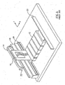
- Fig. 1 illustrates the print head 12 and cable carrier 14 of a printing system.
- the cable carrier 14 is rigidly attached to the print head 12 by a plate 16 configured to allow the ink supply tubing and data and electronic cables to pass through to the cable carrier 14.
- the cable carrier 14 is generally flexible and travels along a support structure 18.
- the print head 12 is configured to travel on a linear bearing zip by a linear motor (not shown) along the "Y"-axis. As the print head 12 moves along the "Y"-axis, the cable carrier 14 rotates as indicated by arrow 22.
- the height of the print head above the substrate may be as small as 2mm.
- the weight of the tubing, hoses and cables is generally relatively heavy and causes vibration. Any vibration of the ink delivery system owing to the weight and movement of the tubing and cables, for example, will cause the print head to vibrate because of the rigidity of the attachment between the ink delivery system and the print heads. The vibration may lead to inaccurate, uneven and poor quality printing results.
- US 4,566,814 discloses a print head carriage assembly which provides parallel guidance of a print head to the platen of a printing system.
- the print head is mounted on a platform.
- Linear movement of the carriage is accomplished by a guide roller; which is spring-biased towards a channel, at one side of the platform and by a slide assembly at the other side of the platform.
- US 6,007,190 discloses an ink supply system for an ink jet printer having remotely located large volume ink containers. Ink is supplied from the ink containers to the movable print head by an ink supply carrier assembly which includes a cable carrier track.
- Apparatus and method for protecting print heads from unwanted movement and vibration is provided as defined in claim 1 and in claim 5.
- Fig 2 is a sectional elevation illustration of a print head protecting system, generally designated 50, constructed and operative according to some embodiments of the present invention.
- Figs. 2A and 2B are enlarged sectional details of part of the print head protecting apparatus 50.
- the print head protecting apparatus 50 is described with reference to protecting ink jet printing heads from uncontrolled movement and vibration, but, as will be appreciated by those skilled in the art, the apparatus is not limited thereto.
- the print head protecting apparatus 50 comprises a linear bearing component 52 ( Fig. 2B ) and a pin connection component 54 ( Fig. 2A ) which isolate the unwanted movement and vibration of the cable carrier 56 from the print head 58 to which a flexible cable carrier 56 is coupled.
- Linear bearing component 52 and pin connection component 54 prevent vibration being transferred from flexible cable carrier 56 to the print head 58.
- Flexible cable carrier 56 may be any suitable cable carrier, such as the cable carrier system supplied by Igus Inc of E. Buffalo, Richmond, USA.
- the flexible cable carrier protects and supports the supply hoses.
- the flexible cable carrier 56 may be similar to cable carrier 14 of Fig. 1 .
- the print head protecting apparatus 50 may be part of a printing system, such as a ink-jet printing machine.
- the print head protecting apparatus 50 also comprises a cable carrier support 60, which supports the cable carrier and is configured to allow the flexible cable carrier 56 to travel along the cable carrier support 60 in the Y-axis in parallel to and together with the movement of the print head 58.
- a plate 64 (which may be metal) is suitable attached to cable carrier 56.
- a pin 70 is suitable attached at the other end 68 of plate 64.
- Pin 70 protrudes from the plate 64.
- Pin connection component 54 comprises a receiver 72, which is suitably attached to print head 58.
- Receiver 72 is configured to receive pin 70 within an elliptical opening formed therein and allow the pin 70 freedom of movement along all axes including the "Z"-axis.
- pin 70 may be suitably attached to print head 58 and receiver 72 may be suitably attached to plate 64.
- Linear bearing component 52 may be a linear bearing track, known in the art, which comprises a generally "U"-channel 74 suitably attached to plate 64 and a track 76 suitably attached to cable carrier support 60.
- Channel 74 moves along the longitudinal axis of the linear bearing component 52.
- the two components of the print head protecting apparatus 50 provide protection at two levels. Any vibration or sudden movement of the cable carrier 56 is transferred to the plate 64. At a first level, the linear bearing of the linear bearing component 52 absorbs at least part of the energy being transferred. Secondly, if there is any continuing vibration, which travels down to pin 70, the receiver 72 allows the pin 70 to vibrate within certain limits without directly affecting the print head itself. In a further embodiment, a rubber or silicone protector may be inserted within receiver 72 to provide yet further absorption of any sundry vibration.
- linear bearing component 52 and pin connection component 54 prevent vibration being transferred from the flexible cable carrier 56 to the print head 58.
- the apparatus 50 is described with reference to protecting ink jet printing heads, but, as will be appreciated by those skilled in the art, the apparatus is not limited to ink jet printing heads.
Landscapes
- Accessory Devices And Overall Control Thereof (AREA)
- Ink Jet (AREA)
- Electronic Switches (AREA)
- Printers Characterized By Their Purpose (AREA)
- Vehicle Body Suspensions (AREA)
- Body Structure For Vehicles (AREA)
Abstract
Description
- The present invention is generally related to apparatus for protecting a print head from a flexible cable carrier with which it is coupled and in particular is related to apparatus for protecting ink-jet printing heads.
- During printing, for example ink jet printing, the print array heads may be moved along one or more axes to print on to the substrate. Ink is generally supplied to the print heads by an ink delivery system. As the print heads moves, the ink delivery system attached to the print heads travels with the print heads. The ink delivery system may include tubing and hoses for supplying the ink. In addition, the printing system includes cables for data transfer and control information as well as electricity supply cables. Commonly, the tubing, hoses and cables associated with the printing system are enclosed within a cable carrier, which is rigidly attached to the print heads that they move together with the movement of the print heads.
- Reference is now made to
Fig. 1 , which illustrates theprint head 12 andcable carrier 14 of a printing system. Thecable carrier 14 is rigidly attached to theprint head 12 by aplate 16 configured to allow the ink supply tubing and data and electronic cables to pass through to thecable carrier 14. Thecable carrier 14 is generally flexible and travels along asupport structure 18. Theprint head 12 is configured to travel on a linear bearing zip by a linear motor (not shown) along the "Y"-axis. As theprint head 12 moves along the "Y"-axis, thecable carrier 14 rotates as indicated byarrow 22. - The height of the print head above the substrate may be as small as 2mm. The weight of the tubing, hoses and cables is generally relatively heavy and causes vibration. Any vibration of the ink delivery system owing to the weight and movement of the tubing and cables, for example, will cause the print head to vibrate because of the rigidity of the attachment between the ink delivery system and the print heads. The vibration may lead to inaccurate, uneven and poor quality printing results.
-
US 4,566,814 discloses a print head carriage assembly which provides parallel guidance of a print head to the platen of a printing system. The print head is mounted on a platform. Linear movement of the carriage is accomplished by a guide roller; which is spring-biased towards a channel, at one side of the platform and by a slide assembly at the other side of the platform. -
US 6,007,190 discloses an ink supply system for an ink jet printer having remotely located large volume ink containers. Ink is supplied from the ink containers to the movable print head by an ink supply carrier assembly which includes a cable carrier track. - It would be advantageous to provide an apparatus that overcomes the disadvantages of the prior art,
- Apparatus and method for protecting print heads from unwanted movement and vibration is provided as defined in claim 1 and in claim 5.
- The subject matter regarded as the invention is particularly pointed out and distinctly claimed in the concluding portion of the specification. The invention, however, both as to organization and method of operation, together with objects, features, and advantages thereof, may best be understood by reference to the following detailed description when read with the accompanying drawings in which:
-
Fig. 1 is an illustration of the print-head and cable carrier of a prior art printing system; -
Fig. 2 is a sectional elevation illustration of a print-head protecting apparatus constructed and operative according to some embodiments of the present invention; and -
Figs. 2A and 2B are enlarged sectional details of the print-head protecting apparatus. - It will be appreciated that for simplicity and clarity of illustration, elements shown in the figures have not necessarily been drawn to scale. For example, the dimensions of some of the elements may be exaggerated relative to other elements for clarity. Further, where considered appropriate, reference numerals may be repeated among the figures to indicate corresponding or analogous elements.
- In the following detailed description, numerous specific details are set forth in order to provide a thorough understanding of the invention. However, it will be understood by those skilled in the art that the present invention may be practiced without these specific details. In other instances, well-known methods, procedures, and components have not been described in detail so as not to obscure the present invention.
- Reference is now made to
Figs. 2, 2A and 2B. Fig 2 is a sectional elevation illustration of a print head protecting system, generally designated 50, constructed and operative according to some embodiments of the present invention.Figs. 2A and 2B are enlarged sectional details of part of the printhead protecting apparatus 50. - For exemplary purposes only, the print
head protecting apparatus 50 is described with reference to protecting ink jet printing heads from uncontrolled movement and vibration, but, as will be appreciated by those skilled in the art, the apparatus is not limited thereto. - The print
head protecting apparatus 50 comprises a linear bearing component 52 (Fig. 2B ) and a pin connection component 54 (Fig. 2A ) which isolate the unwanted movement and vibration of thecable carrier 56 from theprint head 58 to which aflexible cable carrier 56 is coupled.Linear bearing component 52 andpin connection component 54 prevent vibration being transferred fromflexible cable carrier 56 to theprint head 58. -
Flexible cable carrier 56 may be any suitable cable carrier, such as the cable carrier system supplied by Igus Inc of E. Providence, Richmond, USA. The flexible cable carrier protects and supports the supply hoses. Theflexible cable carrier 56 may be similar tocable carrier 14 ofFig. 1 . - The print
head protecting apparatus 50 may be part of a printing system, such as a ink-jet printing machine. The printhead protecting apparatus 50 also comprises acable carrier support 60, which supports the cable carrier and is configured to allow theflexible cable carrier 56 to travel along thecable carrier support 60 in the Y-axis in parallel to and together with the movement of theprint head 58. - One
end 66 of a plate 64 (which may be metal) is suitable attached tocable carrier 56. At theother end 68 ofplate 64, apin 70 is suitable attached.Pin 70 protrudes from theplate 64.Pin connection component 54 comprises areceiver 72, which is suitably attached toprint head 58.Receiver 72 is configured to receivepin 70 within an elliptical opening formed therein and allow thepin 70 freedom of movement along all axes including the "Z"-axis. - In an alternative embodiment,
pin 70 may be suitably attached to printhead 58 andreceiver 72 may be suitably attached toplate 64. -
Linear bearing component 52 may be a linear bearing track, known in the art, which comprises a generally "U"-channel 74 suitably attached toplate 64 and atrack 76 suitably attached tocable carrier support 60.Channel 74 moves along the longitudinal axis of the linear bearingcomponent 52. - In practice, as the
print head 58 moves along the "Y"-axis,pin 70 is moved along with it. "U"-channel 74, which is attached toplate 64 also moves along the "Y"-axis on the linear bearingtrack 76. Thecable carrier 56 is rotated and also effectively moves along thecable carrier support 60 in parallel with theprint head 58. - The two components of the print head protecting apparatus 50 (
linear bearing component 52 and pin connection component 54) provide protection at two levels. Any vibration or sudden movement of thecable carrier 56 is transferred to theplate 64. At a first level, the linear bearing of thelinear bearing component 52 absorbs at least part of the energy being transferred. Secondly, if there is any continuing vibration, which travels down topin 70, thereceiver 72 allows thepin 70 to vibrate within certain limits without directly affecting the print head itself. In a further embodiment, a rubber or silicone protector may be inserted withinreceiver 72 to provide yet further absorption of any sundry vibration. - Thus,
linear bearing component 52 andpin connection component 54 prevent vibration being transferred from theflexible cable carrier 56 to theprint head 58. - The
apparatus 50 is described with reference to protecting ink jet printing heads, but, as will be appreciated by those skilled in the art, the apparatus is not limited to ink jet printing heads. - While certain features of the invention have been illustrated and described herein, many modifications, substitutions, changes, and equivalents will now occur to those of ordinary skill in the art. It is, therefore, to be understood that the appended claims are intended to cover all such modifications and changes.
Claims (5)
- An apparatus comprising:at least one print head (58), ;a movable component attachable to a flexible cable carrier which protects and supports ink supply hoses, said movable component being coupled to said at least one print head (58), andan isolating component attachable to said movable component, for isolating uncontrolled movement and vibration of said flexible cable carrier (56) from said atleast one print head (58), wherein said isolating component comprises a linear bearing track (52); characterized in that thesaid movable component comprises:(i) a pin (70) attached to a second end (68) of said movable component, said second end (68) being distal from a first end (66) of said movable component, and wherein said isolating component further comprises a receiver (72) attached to said print head (58), said receiver (72) being configured to receive said pin (70) and allow said pin (70) freedom of movement in at least one direction;
or(ii) a receiver (72) attached to the second end (68) of said movable component, said second end (68) being distal from said first end (66), and wherein said isolating component further comprises a pin (70) attached to said print head (58), said receiver (72) being configured to receive said pin (70) and allow said pin (70) freedom of movement in at least one direction. - The apparatus according to claim 1, wherein said movable component comprises a plate (64) attached at one end to said flexible cable carrier (56).
- The apparatus according to claims 1 and 2, wherein said receiver (72) comprises a rubber protector.
- The apparatus according to claims 1 and 2, wherein said receiver (72) comprises a silicone protector.
- A method for isolating uncontrolled movement and vibration of a print head (58) from a flexible cable carrier (56) which protects and supports ink supply hoses, said print head (58) being coupled to said flexible cable carrier (56), said method comprising:attaching a first one end (66) of a movable component to said flexible cable carrier (56);attaching an isolating component comprising a linear bearing track (52) to said movable component; characterized in that(i) attaching a pin (70) to a second end (68) of said movable component, said second end (68) being distal from said first end (66), and a receiver (72) to said print head (58), said receiver (72) being configured to receive said pin (70) and allow said pin (70) freedom of movement in at least one direction;
or(ii) attaching a receiver (72) to a second end (68) of said movable component, said second end (68) being distal from said first end (66), and a pin (70) to said print head (58), said receiver (72) being configured to receive said pin (70) and allow said pin (70) freedom of movement in at least one direction.
Applications Claiming Priority (3)
| Application Number | Priority Date | Filing Date | Title |
|---|---|---|---|
| US24214100P | 2000-10-23 | 2000-10-23 | |
| US242141P | 2000-10-23 | ||
| PCT/IL2001/000974 WO2002034524A2 (en) | 2000-10-23 | 2001-10-22 | Apparatus and method for protecting printing heads |
Publications (3)
| Publication Number | Publication Date |
|---|---|
| EP1333982A2 EP1333982A2 (en) | 2003-08-13 |
| EP1333982A4 EP1333982A4 (en) | 2005-06-15 |
| EP1333982B1 true EP1333982B1 (en) | 2011-03-09 |
Family
ID=22913610
Family Applications (1)
| Application Number | Title | Priority Date | Filing Date |
|---|---|---|---|
| EP01980868A Expired - Lifetime EP1333982B1 (en) | 2000-10-23 | 2001-10-22 | Apparatus and method for protecting printing heads |
Country Status (7)
| Country | Link |
|---|---|
| US (1) | US6726307B2 (en) |
| EP (1) | EP1333982B1 (en) |
| AT (1) | ATE500969T1 (en) |
| AU (2) | AU2002212650A1 (en) |
| DE (1) | DE60144193D1 (en) |
| IL (1) | IL155512A0 (en) |
| WO (2) | WO2002034524A2 (en) |
Families Citing this family (2)
| Publication number | Priority date | Publication date | Assignee | Title |
|---|---|---|---|---|
| US9610791B2 (en) | 2015-05-05 | 2017-04-04 | Océ-Technologies B.V. | Print head mounting structure |
| US10343430B2 (en) * | 2016-09-22 | 2019-07-09 | Océ Holding B.V. | Assembly for moving a carriage |
Family Cites Families (13)
| Publication number | Priority date | Publication date | Assignee | Title |
|---|---|---|---|---|
| CH320467A (en) * | 1954-05-29 | 1957-03-31 | Contraves Ag | Shock-absorbing connection between mechanical flat parts |
| US4566814A (en) * | 1983-04-06 | 1986-01-28 | Standard Precision, Inc. | Print head carriage assembly |
| JPS63503051A (en) * | 1986-04-07 | 1988-11-10 | エヌ・シー・アール・インターナショナル・インコーポレイテッド | printer |
| EP0602020B1 (en) * | 1988-12-29 | 1998-06-10 | Canon Kabushiki Kaisha | Ink jet recording head and ink jet recording apparatus |
| ES2048024B1 (en) * | 1990-04-25 | 1995-02-16 | Fujitsu Ltd | PRINTING DEVICE PROVIDED WITH HEAD INTERVAL ADJUSTMENT DEVICE. |
| JPH04216971A (en) * | 1990-12-17 | 1992-08-07 | Oki Electric Ind Co Ltd | Recording device |
| US5369429A (en) * | 1993-10-20 | 1994-11-29 | Lasermaster Corporation | Continuous ink refill system for disposable ink jet cartridges having a predetermined ink capacity |
| JPH08156353A (en) * | 1994-10-07 | 1996-06-18 | Canon Inc | Printing equipment |
| US6007190A (en) | 1994-12-29 | 1999-12-28 | Encad, Inc. | Ink supply system for an ink jet printer having large volume ink containers |
| US5719608A (en) | 1995-05-04 | 1998-02-17 | Calcomp Inc. | Constant flow ink delivery system |
| JP3841315B2 (en) * | 1995-12-26 | 2006-11-01 | キヤノン株式会社 | Printing apparatus and printing method used in the apparatus |
| US6068370A (en) * | 1996-08-30 | 2000-05-30 | Hewlett-Packard Company | Fluidic delivery system with tubing and manifolding for an off-axis printing system |
| KR100230318B1 (en) * | 1997-07-30 | 1999-11-15 | 윤종용 | Pressure controlling apparatus for laser printer |
-
2001
- 2001-10-22 WO PCT/IL2001/000974 patent/WO2002034524A2/en not_active Ceased
- 2001-10-22 US US09/982,985 patent/US6726307B2/en not_active Expired - Fee Related
- 2001-10-22 DE DE60144193T patent/DE60144193D1/en not_active Expired - Lifetime
- 2001-10-22 WO PCT/IL2001/000972 patent/WO2002034543A2/en not_active Ceased
- 2001-10-22 IL IL15551201A patent/IL155512A0/en not_active IP Right Cessation
- 2001-10-22 AU AU2002212650A patent/AU2002212650A1/en not_active Abandoned
- 2001-10-22 AT AT01980868T patent/ATE500969T1/en not_active IP Right Cessation
- 2001-10-22 EP EP01980868A patent/EP1333982B1/en not_active Expired - Lifetime
- 2001-10-22 AU AU1265202A patent/AU1265202A/en active Pending
Also Published As
| Publication number | Publication date |
|---|---|
| WO2002034524A2 (en) | 2002-05-02 |
| WO2002034543A3 (en) | 2002-09-06 |
| WO2002034543A2 (en) | 2002-05-02 |
| AU1265202A (en) | 2002-05-06 |
| EP1333982A2 (en) | 2003-08-13 |
| EP1333982A4 (en) | 2005-06-15 |
| AU2002212650A1 (en) | 2002-05-06 |
| IL155512A0 (en) | 2003-11-23 |
| US6726307B2 (en) | 2004-04-27 |
| ATE500969T1 (en) | 2011-03-15 |
| DE60144193D1 (en) | 2011-04-21 |
| US20020070996A1 (en) | 2002-06-13 |
| WO2002034524A3 (en) | 2002-07-04 |
Similar Documents
| Publication | Publication Date | Title |
|---|---|---|
| EP0564297B1 (en) | Portable printing apparatus | |
| EP0924092A2 (en) | Stationary Pen Printer | |
| EP0826504A3 (en) | Fluid delivery system with tubing for printing system | |
| US6494630B2 (en) | Datum structure for compact print cartridge | |
| EP0873879A3 (en) | An ink jet recording apparatus | |
| JP2003300358A5 (en) | ||
| SG48435A1 (en) | Recording apparatus with improved head installation mechanism | |
| EP0540344A3 (en) | Recovery mechanism and an ink jet recording apparatus using the recovery mechanism | |
| JPH01168475A (en) | Support device for flexible elongate component part | |
| ATE194555T1 (en) | INKJET RECORDING HEAD AND ASSOCIATED APPARATUS | |
| EP3552832A1 (en) | Printer | |
| JPH01176565A (en) | Inkjet recording apparatus | |
| US6726307B2 (en) | Apparatus and method for protecting printing heads | |
| US8123210B1 (en) | Paper feeding assembly for printers | |
| JP2011230416A (en) | Inkjet recorder | |
| CA2304520A1 (en) | Large format ink-jet colour printer | |
| US8905518B2 (en) | Recording apparatus including a supporting member that supports a connecting member | |
| HUP0202559A3 (en) | Spring pad, carriage assembly for holding a printhead assembly of an inkjet printing system, and method for electrically coupled a print cartridge including an inkjet printhead assembly and the printer carriage | |
| IL155512A (en) | Apparatus and method for protecting printing heads | |
| US5548311A (en) | Mount for replaceable ink jet head | |
| JPH0976485A (en) | Ink jet recording device | |
| JPS63154354A (en) | Liquid jet recorder | |
| US20120105542A1 (en) | Inclined motor in an inkjet printer | |
| KR100186587B1 (en) | Device for transferring data from an ink-jet printer to a carrier | |
| JP2022123632A (en) | Liquid discharge device |
Legal Events
| Date | Code | Title | Description |
|---|---|---|---|
| PUAI | Public reference made under article 153(3) epc to a published international application that has entered the european phase |
Free format text: ORIGINAL CODE: 0009012 |
|
| 17P | Request for examination filed |
Effective date: 20030519 |
|
| AK | Designated contracting states |
Designated state(s): AT BE CH CY DE DK ES FI FR GB GR IE IT LI LU MC NL PT SE TR |
|
| AX | Request for extension of the european patent |
Extension state: AL LT LV MK RO SI |
|
| A4 | Supplementary search report drawn up and despatched |
Effective date: 20050504 |
|
| RIC1 | Information provided on ipc code assigned before grant |
Ipc: 7B 41J 29/08 B Ipc: 7B 41J 2/17 A |
|
| RAP1 | Party data changed (applicant data changed or rights of an application transferred) |
Owner name: HEWLETT-PACKARD INDUSTRIAL PRINTING |
|
| 17Q | First examination report despatched |
Effective date: 20090427 |
|
| GRAP | Despatch of communication of intention to grant a patent |
Free format text: ORIGINAL CODE: EPIDOSNIGR1 |
|
| GRAJ | Information related to disapproval of communication of intention to grant by the applicant or resumption of examination proceedings by the epo deleted |
Free format text: ORIGINAL CODE: EPIDOSDIGR1 |
|
| GRAP | Despatch of communication of intention to grant a patent |
Free format text: ORIGINAL CODE: EPIDOSNIGR1 |
|
| GRAS | Grant fee paid |
Free format text: ORIGINAL CODE: EPIDOSNIGR3 |
|
| GRAA | (expected) grant |
Free format text: ORIGINAL CODE: 0009210 |
|
| AK | Designated contracting states |
Kind code of ref document: B1 Designated state(s): AT BE CH CY DE DK ES FI FR GB GR IE IT LI LU MC NL PT SE TR |
|
| REG | Reference to a national code |
Ref country code: GB Ref legal event code: FG4D |
|
| REG | Reference to a national code |
Ref country code: CH Ref legal event code: EP |
|
| REG | Reference to a national code |
Ref country code: IE Ref legal event code: FG4D |
|
| REF | Corresponds to: |
Ref document number: 60144193 Country of ref document: DE Date of ref document: 20110421 Kind code of ref document: P |
|
| REG | Reference to a national code |
Ref country code: DE Ref legal event code: R096 Ref document number: 60144193 Country of ref document: DE Effective date: 20110421 |
|
| REG | Reference to a national code |
Ref country code: NL Ref legal event code: VDEP Effective date: 20110309 |
|
| PG25 | Lapsed in a contracting state [announced via postgrant information from national office to epo] |
Ref country code: SE Free format text: LAPSE BECAUSE OF FAILURE TO SUBMIT A TRANSLATION OF THE DESCRIPTION OR TO PAY THE FEE WITHIN THE PRESCRIBED TIME-LIMIT Effective date: 20110309 Ref country code: ES Free format text: LAPSE BECAUSE OF FAILURE TO SUBMIT A TRANSLATION OF THE DESCRIPTION OR TO PAY THE FEE WITHIN THE PRESCRIBED TIME-LIMIT Effective date: 20110620 Ref country code: GR Free format text: LAPSE BECAUSE OF FAILURE TO SUBMIT A TRANSLATION OF THE DESCRIPTION OR TO PAY THE FEE WITHIN THE PRESCRIBED TIME-LIMIT Effective date: 20110610 |
|
| PG25 | Lapsed in a contracting state [announced via postgrant information from national office to epo] |
Ref country code: NL Free format text: LAPSE BECAUSE OF FAILURE TO SUBMIT A TRANSLATION OF THE DESCRIPTION OR TO PAY THE FEE WITHIN THE PRESCRIBED TIME-LIMIT Effective date: 20110309 Ref country code: CY Free format text: LAPSE BECAUSE OF FAILURE TO SUBMIT A TRANSLATION OF THE DESCRIPTION OR TO PAY THE FEE WITHIN THE PRESCRIBED TIME-LIMIT Effective date: 20110309 Ref country code: AT Free format text: LAPSE BECAUSE OF FAILURE TO SUBMIT A TRANSLATION OF THE DESCRIPTION OR TO PAY THE FEE WITHIN THE PRESCRIBED TIME-LIMIT Effective date: 20110309 Ref country code: FI Free format text: LAPSE BECAUSE OF FAILURE TO SUBMIT A TRANSLATION OF THE DESCRIPTION OR TO PAY THE FEE WITHIN THE PRESCRIBED TIME-LIMIT Effective date: 20110309 |
|
| PG25 | Lapsed in a contracting state [announced via postgrant information from national office to epo] |
Ref country code: BE Free format text: LAPSE BECAUSE OF FAILURE TO SUBMIT A TRANSLATION OF THE DESCRIPTION OR TO PAY THE FEE WITHIN THE PRESCRIBED TIME-LIMIT Effective date: 20110309 |
|
| PG25 | Lapsed in a contracting state [announced via postgrant information from national office to epo] |
Ref country code: PT Free format text: LAPSE BECAUSE OF FAILURE TO SUBMIT A TRANSLATION OF THE DESCRIPTION OR TO PAY THE FEE WITHIN THE PRESCRIBED TIME-LIMIT Effective date: 20110711 |
|
| PLBE | No opposition filed within time limit |
Free format text: ORIGINAL CODE: 0009261 |
|
| STAA | Information on the status of an ep patent application or granted ep patent |
Free format text: STATUS: NO OPPOSITION FILED WITHIN TIME LIMIT |
|
| PGFP | Annual fee paid to national office [announced via postgrant information from national office to epo] |
Ref country code: FR Payment date: 20111028 Year of fee payment: 11 |
|
| 26N | No opposition filed |
Effective date: 20111212 |
|
| PG25 | Lapsed in a contracting state [announced via postgrant information from national office to epo] |
Ref country code: DK Free format text: LAPSE BECAUSE OF FAILURE TO SUBMIT A TRANSLATION OF THE DESCRIPTION OR TO PAY THE FEE WITHIN THE PRESCRIBED TIME-LIMIT Effective date: 20110309 |
|
| REG | Reference to a national code |
Ref country code: DE Ref legal event code: R097 Ref document number: 60144193 Country of ref document: DE Effective date: 20111212 |
|
| PG25 | Lapsed in a contracting state [announced via postgrant information from national office to epo] |
Ref country code: MC Free format text: LAPSE BECAUSE OF NON-PAYMENT OF DUE FEES Effective date: 20111031 Ref country code: IT Free format text: LAPSE BECAUSE OF FAILURE TO SUBMIT A TRANSLATION OF THE DESCRIPTION OR TO PAY THE FEE WITHIN THE PRESCRIBED TIME-LIMIT Effective date: 20110309 |
|
| REG | Reference to a national code |
Ref country code: CH Ref legal event code: PL |
|
| PG25 | Lapsed in a contracting state [announced via postgrant information from national office to epo] |
Ref country code: CH Free format text: LAPSE BECAUSE OF NON-PAYMENT OF DUE FEES Effective date: 20111031 Ref country code: LI Free format text: LAPSE BECAUSE OF NON-PAYMENT OF DUE FEES Effective date: 20111031 |
|
| REG | Reference to a national code |
Ref country code: IE Ref legal event code: MM4A |
|
| PG25 | Lapsed in a contracting state [announced via postgrant information from national office to epo] |
Ref country code: IE Free format text: LAPSE BECAUSE OF NON-PAYMENT OF DUE FEES Effective date: 20111022 |
|
| PG25 | Lapsed in a contracting state [announced via postgrant information from national office to epo] |
Ref country code: LU Free format text: LAPSE BECAUSE OF NON-PAYMENT OF DUE FEES Effective date: 20111022 |
|
| REG | Reference to a national code |
Ref country code: FR Ref legal event code: ST Effective date: 20130628 |
|
| PG25 | Lapsed in a contracting state [announced via postgrant information from national office to epo] |
Ref country code: FR Free format text: LAPSE BECAUSE OF NON-PAYMENT OF DUE FEES Effective date: 20121031 |
|
| PG25 | Lapsed in a contracting state [announced via postgrant information from national office to epo] |
Ref country code: TR Free format text: LAPSE BECAUSE OF FAILURE TO SUBMIT A TRANSLATION OF THE DESCRIPTION OR TO PAY THE FEE WITHIN THE PRESCRIBED TIME-LIMIT Effective date: 20110309 |
|
| PGFP | Annual fee paid to national office [announced via postgrant information from national office to epo] |
Ref country code: GB Payment date: 20130923 Year of fee payment: 13 |
|
| PGFP | Annual fee paid to national office [announced via postgrant information from national office to epo] |
Ref country code: DE Payment date: 20130920 Year of fee payment: 13 |
|
| REG | Reference to a national code |
Ref country code: DE Ref legal event code: R119 Ref document number: 60144193 Country of ref document: DE |
|
| GBPC | Gb: european patent ceased through non-payment of renewal fee |
Effective date: 20141022 |
|
| PG25 | Lapsed in a contracting state [announced via postgrant information from national office to epo] |
Ref country code: DE Free format text: LAPSE BECAUSE OF NON-PAYMENT OF DUE FEES Effective date: 20150501 Ref country code: GB Free format text: LAPSE BECAUSE OF NON-PAYMENT OF DUE FEES Effective date: 20141022 |