EP1333747B1 - Telescopic extension for an electric household appliance - Google Patents
Telescopic extension for an electric household appliance Download PDFInfo
- Publication number
- EP1333747B1 EP1333747B1 EP01993418A EP01993418A EP1333747B1 EP 1333747 B1 EP1333747 B1 EP 1333747B1 EP 01993418 A EP01993418 A EP 01993418A EP 01993418 A EP01993418 A EP 01993418A EP 1333747 B1 EP1333747 B1 EP 1333747B1
- Authority
- EP
- European Patent Office
- Prior art keywords
- sleeve
- outer tube
- inner tube
- telescopic extension
- tube
- Prior art date
- Legal status (The legal status is an assumption and is not a legal conclusion. Google has not performed a legal analysis and makes no representation as to the accuracy of the status listed.)
- Expired - Lifetime
Links
Images


Classifications
-
- A—HUMAN NECESSITIES
- A47—FURNITURE; DOMESTIC ARTICLES OR APPLIANCES; COFFEE MILLS; SPICE MILLS; SUCTION CLEANERS IN GENERAL
- A47L—DOMESTIC WASHING OR CLEANING; SUCTION CLEANERS IN GENERAL
- A47L9/00—Details or accessories of suction cleaners, e.g. mechanical means for controlling the suction or for effecting pulsating action; Storing devices specially adapted to suction cleaners or parts thereof; Carrying-vehicles specially adapted for suction cleaners
- A47L9/24—Hoses or pipes; Hose or pipe couplings
- A47L9/242—Hose or pipe couplings
- A47L9/244—Hose or pipe couplings for telescopic or extensible hoses or pipes
Abstract
Description
- The present invention relates to a telescopic extension for an electric household appliance.
- EP-B1-0 520 534 discloses a telescopic extension for a vacuum cleaner, comprising an inner tube and an outer tube sealingly slidable one inside the other, a sleeve, a means for constraining the inner tube and outer tube, a thrust slider and an actuating pushbutton.
- The inner tube is provided with a row of recesses having a predefined shape and the outer tube is provided with an end tubular portion with a flared shape which is formed as one piece therewith and inside which the sleeve is fastened.
- The constraining means consists of a cylinder piece integral with a plate provided with a pin. By means of the pin and the plate, the cylinder piece is rotatably supported in a hollow seat of the sleeve. The seat has, formed in it, a slit by means of which the cylinder piece is able to engage with a recess of the inner tube and disengage from the recess .
- In this telescopic extension, the thrust slider is operationally connected to the actuating pushbutton, is slidably supported inside the seat of the sleeve and is subject to the action of resilient means.
- The resilient means cause the thrust slider to engage with the plate integral with the cylinder piece to force the latter into the recess of the inner tube and lock the inner tube inside the outer tube. As a result, the extension assumes a predefined length.
- In order to adjust the length of the extension, the actuating pushbutton is pushed manually against the action of the resilient means so that the thrust slider is able to disengage from the plate and leave the cylinder piece free to come out of the recess of the inner tube, releasing the inner tube from the outer tube. By means of sliding of the inner tube inside the outer tube, the extension assumes the desired length.
- In order to assemble the extension, the sleeve is fitted onto the inner tube and the constraining means, the slider/pushbutton assembly and the resilient means are pre-mounted in the hollow seat of the sleeve. Then, the inner tube is mounted inside the outer tube and the sleeve is inserted into the end tubular portion, centred with respect thereto, passing the slider/pushbutton assembly through an end opening of the outer tube. A telescopic extension according to the preamble of
claim 1 is known for example from EP-A-1033103. - The object of the present invention is to improve the abovementioned extension, reducing the number of components and making assembly easier.
- The present invention relates to a telescopic extension for an electric household appliance, comprising:
- a) an inner tube and an outer tube slidable one inside the other,
- b) a sleeve fastened to said outer tube,
- c) a constraining means capable of making integral said inner tube and said outer tube,
- d) a thrust slider which can be engaged with said constraining means under the action of resilient means, and
- e) actuating means operationally connected to said thrust slider,
- f) said inner tube being provided with a row of recesses having a predefined shape,
- g) said sleeve being arranged between said inner tube and said outer tube,
- h) said constraining means and said thrust slider being movably supported by said sleeve,
- i) said thrust slider acting on said constraining means under the action of said resilient means to force said constraining means into a recess of said inner tube and lock said inner tube with respect to said outer tube,
- j) said actuating means being capable of disengaging said thrust slider from said constraining means to leave said constraining means free to move radially and come out of said recess, releasing said inner tube from said outer tube and allowing said inner tube to slide with respect to said outer tube in order to adjust the length of said extension,
- k) said constraining means having an appendix,
- I) said appendix consists of a resilient tongue having one end formed as one piece with said sleeve, said resilient tongue being radially movable with respect to said sleeve,
- m) said constraining means consists of a projection on said resilient tongue, and
- n) said thrust slider can be engaged with said resilient tongue to force said projection into a recess of said inner tube and thus lock said inner and outer tubes and can be disengaged from said resilient tongue to allow said projection to come out of said recess of said inner tube and thus release said inner and outer tubes, characterized in that said thrust slider is movably supported by said sleeve, said sleeve has a longitudinal cavity able to house said thrust slider and said resilient means, and the resilient tongue comprises a ramp and the thrust slider comprises a plate with an inclined wall, the ramp and the inclined wall cooperating for forcing the projection into a recess, the plate remaining embedded inside the cavity, being flush with the external surface of the sleeve and being radially constrained by the outer tube.
- Advantageously, said longitudinal cavity has an opening inside which said resilient tongue is located, said end of said resilient tongue being formed as one piece with a wall of said longitudinal cavity.
- Preferably, said sleeve has an internal longitudinal boss which is located underneath said longitudinal cavity and said inner tube has a longitudinal groove with which said internal longitudinal boss of said sleeve is coupled in order to centre said sleeve with respect to said inner tube.
- Preferably, said longitudinal groove of said inner tube has a bottom wall in which said recesses are present.
- Advantageously, said outer tube has a lateral opening which extends as far as one end thereof and said sleeve has an external longitudinal relief which engages with said lateral opening to couple said outer tube with said sleeve and centre said outer tube with respect to said sleeve.
- Preferably, said sleeve is provided with a collar against which said end of said outer tube comes into contact, said collar and said external relief having a thickness substantially equal to that of said outer tube so that it remains flush with said collar and said external relief .
- Advantageously, said thrust slider is provided with an upper head able to be inserted by means of pressure into a niche in said actuating means.
- Preferably, said sleeve, said resilient tongue and said projection are made of plastic material.
- Advantageously, said outer tube has a cross-section with a substantially constant diameter.
- The telescopic projection according to the invention has the advantage that it is compact, low-cost and simple to assemble.
- Characteristic features and advantages of the invention will now be illustrated with reference to an embodiment shown by way of a nonlimiting example in the accompanying drawings, in which:
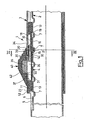
- Fig. 1 is a partial, longitudinal sectional view of a telescopic extension for an electric household appliance according to the invention, in the locked condition;
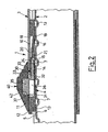
- Fig. 2 shows the extension according to Fig. 1 in the unlocked condition;
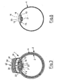
- Fig. 3 is a cross-sectional view taken along the plane III-III in Fig. 1;
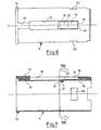
- Fig. 4 is a partial top view, on a reduced scale, of the extension of Fig. 1;
- Fig. 5 is a partial, perspective view of an outer tube, a sleeve and an inner tube of the extension of Fig. 1 in the disassembled condition;
- Fig. 6 is a top view of the sleeve of the extension of Fig. 1;
- Fig. 7 is a longitudinal sectional view of the sleeve of Fig. 6;
- Fig. 8 is a cross-sectional view taken along the plane VIII-VIII in Fig. 7;
- Fig. 9 is a bottom view of a pushbutton and a thrust slider of the extension of Fig. 1;
- Fig. 10 is a longitudinal sectional view of the pushbutton and the thrust slider of Fig. 9;
- Fig. 11 is a cross-sectional taken view along the plane XI-XI in Fig. 10;
- Figs. 12 and 13 are respectively a right-hand side view and top view of the pushbutton and thrust slider of Fig. 9.
- Figs. 1, 2 and 3 show a telescopic extension for an electric household appliance, such as a vacuum cleaner, numbered on the whole with 1. The
extension 1 comprises aninner tube 2, anouter tube 3 and asleeve 4 arranged between the inner tube and the outer tube. - The inner tube and
outer tube - The
inner tube 2 has alongitudinal groove 5, with a substantially parallelepiped shape, having a bottom wall 6 (Fig. 4) in which a row ofrecesses 7 with a partially cylindrical shape is formed. - The
sleeve 4 has a longitudinal cavity 10 (Figs. 6-8), anexternal relief 11, acollar 12 and an internal boss 13 (Fig. 7). Theexternal relief 11 has a substantially parallelepiped shape and is aligned with thecavity 10. Theinternal boss 13 has a substantially parallelepiped shape and a length nearly the same as that of thesleeve 4. - The
cavity 10 has abottom wall 14 in which anopening 15 is formed. Aresilient tongue 16 integral with thesleeve 4 is located in the opening 15. Theresilient tongue 16 projects from awall 18 of the opening 15 and has oneend 19 formed as one piece with thewall 18. Theresilient tongue 16 has on the upper side aninclined ramp 20 and on the lower side a tooth-shaped projection 21. Theresilient tongue 16 is movable radially with respect to thesleeve 4 and, during its centripetal radial movements, causes theprojection 21 to penetrate into arecess 7 of the tube 2 (Fig. 1), whereas, during its centrifugal radial movements, it extracts theprojection 21 from the recess 7 (Fig. 2). Therefore, theprojection 21 forms a means for constraining theinner tube 2 andouter tube 3, thesleeve 4 being made integral with theouter tube 4, as will be illustrated further below, and theresilient tongue 16 forms an appendix of theprojection 21. - The
outer tube 3 has alateral opening 22 which extends as far as oneend 23 and engages with theexternal relief 11 of thesleeve 4 until theend 23 of the outer tube comes into contact against thecollar 12 of the sleeve 4 (Fig. 4). Thus the outer tube is coupled with thesleeve 4 and is centred with respect thereto, remaining flush with thecollar 12 and with therelief 11 because the latter have a thickness which is practically the same as that of theouter tube 3. - The
outer tube 3 is fastened to thesleeve 4 by means of two indentations - not shown - which penetrate into twonotches 24 on the sleeve 4 (Figs. 5 and 6). The indentations are formed at the moment of assembly by means of deformation of the wall of thetube 3. - The
longitudinal cavity 10 of thesleeve 4 houses athrust slider 30 and ahelical spring 31. - The thrust slider 30 (Figs. 9-12) consists of a
rectangular plate 32 having aninclined wall 33 able to remain in contact with theinclined ramp 20 of thetongue 16, and atapered wall 34. Ahead 35 which is formed as one piece with the plate projects upwards from theplate 32. Thehead 35 and theplate 32 have ablind hole 36 in which thespring 31 is partially housed. Thespring 31 reacts against awall 37 of thecavity 10 in thesleeve 4 and is mounted pre-stressed so that theinclined wall 33 of theslider 30 is normally in contact with theinclined ramp 20 of the resilient tongue 16 (Fig. 1) and pushes theprojection 21 to penetrate into arecess 7 of theinner tube 2. In this way, thetubes extension 1 with a predefined length. - A pushbutton 40 (Figs. 9-13) is mounted on the
head 35 of the thrust slider 30 (Figs. 9-13). Thepushbutton 40 has aseat 41 provided with aniche 42 into which thehead 35 is inserted with pressure. Thuspushbutton 40 andslider 30 are locked together by means of interference. - The
thrust slider 30 and thepushbutton 40 may be formed as one piece. - The
tubes - The
sleeve 4 is made, for example, of a suitable plastic material. Thethrust slider 30 and thepushbutton 40 are also made of a suitable plastic material. - The
plate 32 of theslider 30 has an elongated and flattened form. It has a thickness practically equal to the depth of thecavity 10 in thesleeve 4. Thus theplate 32 remains embedded inside thecavity 10 and is flush with the external surface of thesleeve 4. - The
extension 1 has transverse dimensions which are minimized. Its compact form is also due to the fact that theresilient tongue 16 is provided with the tooth-shapedprojection 21 which engages with the indented, concave, recesses 7 of theinner tube 2. The increases in transverse dimensions of the inner tube, which would occur with a tongue which can be engaged with outward projecting protrusions of the inner tube, are thus avoided. - The
extension 1, in addition to having a simple and compact design, is also very resistant to stresses because theresilient tongue 16 has a stress resistance much greater than that of a tongue which can be engaged with protrusions projecting from the inner tube and which must have a curved end. - Another advantage of the
extension 1 consists in the fact that the contact between theinclined wall 33 of theslider 30 and theinclined ramp 20 of thetongue 16 extends over a surface and any wear which may occur with use of theextension 1 is uniformly distributed over the entire surface. The presence of thespring 31 prevents the formation of play between theslider 30 and thetongue 16 and ensures correct contact also after prolonged use of the extension. - In order to adjust the length of the
extension 1, thepushbutton 40 is operated manually, displacing it from the position shown in Fig. 1 to the position shown in Fig. 2 so that theslider 30 separates from theresilient tongue 16 and leaves it free to be raised to extract theprojection 21 from therecess 7 of thetube 2, inside which it is inserted. - This allows sliding of the
tube 2 inside thetube 3 until the desired length of theextension 1 is achieved. - Assembly of the
telescopic extension 1 is performed by fitting thesleeve 4 onto theinner tube 2 so that itsinternal boss 13 is coupled with thelongitudinal groove 5 of the inner tube. Theslider 30 with thespring 31 is then mounted in thecavity 10 of thesleeve 4 in a position where itsinclined wall 33 is in contact with theramp 20 of thetongue 16 and pushes theprojection 21 into arecess 7 of theinner tube 2. - At this point, the
outer tube 3 is fitted onto thesleeve 4, coupling itslateral opening 22 with theexternal relief 11 until itsend 23 is brought into contact against thecollar 12 of the sleeve. In this position, thehead 35 of theslider 30 projects outside theopening 22 and the pushbutton 401 may be press-fitted thereon. Therefore, the assembly of theextension 1 requires only a few simple and easy operations.
Claims (9)
- Telescopic extension for an electric household appliance, comprising:a) an inner tube (2) and an outer tube (3) slidable one inside the other,b) a sleeve (4) fastened to said outer tube (3),c) a constraining means (21) capable of making integral said inner tube (2) and said outer tube (3),d) a thrust slider (30) which can be engaged with said constraining means (21) under the action of resilient means (31), ande) actuating means (40) operationally connected to said thrust slider (30),f) said inner tube (2) being provided with a row of recesses (7) having a predefined shape,g) said sleeve (4) being arranged between said inner tube (2) and said outer tube (3),h) said constraining means (21) being movably supported by said sleeve (4),i) said thrust slider (30) acting on said constraining means (21) under the action of said resilient means (31) to force said constraining means (21) into a recess (7) of said inner tube (2) and lock said inner tube (2) with respect to said outer tube (3),j) said actuating means (40) being capable of disengaging said thrust slider (30) from said constraining means (21) to leave said constraining means (21) free to move radially and come out of said recess (7), releasing said inner tube (2) from said outer tube (3) and allowing said inner tube (2) to slide with respect to said outer tube (3) in order to adjust the length of said extension,k) said constraining means (21) having an appendix (16),l) said appendix (16) consists of a resilient tongue having one end (19) formed as one piece with said sleeve (4), said resilient tongue (16) being radially movable with respect to said sleeve (4),m) said constraining means (21) consists of a projection on said resilient tongue (16),n) said thrust slider (30) can be engaged with said resilient tongue (16) to force said projection (21) into a recess (7) of said inner tube (2) and thus lock said inner and outer tubes (2, 3) and can be disengaged from said resilient tongue (16) to allow said projection (21) to come out of said recess (7) of said inner tube (2) and thus release said inner and outer tubes (2, 3),
characterized In that said thrust slider (30) is movably supported by said sleeve (4);o) said sleeve (4) has a longitudinal cavity (10) able to house said thrust slider (30) and said resilient means (31), andp) the resilient tongue (16) comprises a ramp (20) and the thrust slider (30) comprises a plate (32) with an inclined wall (33), the ramp and the inclined wall cooperating for forcing the projection (21) into a recess (7), the plate (32) remaining embedded inside the cavity (10), being flush with the external surface of the sleeve (4) and being radially constrained by the outer tube (3). - Telescopic extension (1) according to Claim 1, characterized in that said longitudinal cavity (10) has an opening (15) inside which said resilient tongue (16) is located, said end (19) of said resilient tongue (16) being formed as one piece with a wall (18) of said longitudinal cavity (10).
- Telescopic extension (1) according to Claim 1, characterized in that said sleeve (4) has an internal longitudinal boss (13) which is located underneath said longitudinal cavity (10) and said inner tube (2) has a longitudinal groove (5) with which said internal longitudinal boss (13) of said sleeve is coupled in order to centre said sleeve (4) with respect to said inner tube (2).
- Telescopic extension (1) according to Claims 1 and 3, characterized in that said longitudinal groove (5) of said inner tube (2) has a bottom wall (6) in which said recesses (7) are present.
- Telescopic extension (1) according to Claim 1, characterized in that said outer tube (3) has a lateral opening (22) which extends as far as one end (23) thereof and said sleeve (4) has an external longitudinal relief (11) which engages with said lateral opening (22) to couple said outer tube (3) with said sleeve (4) and centre said outer tube (3) with respect to said sleeve (4).
- Telescopic extension (1) according to Claim 5, characterized in that said sleeve (4) is provided with a collar (12) against which said end (23) of said outer tube (3) comes into contact, said collar (12) and said external relief (11) having a thickness substantially equal to that of said outer tube (3) so that It remains flush with said collar (12) and said external relief (11).
- Telescopic extension (1) according to Claim 1, characterized in that said thrust slider (30) is provided with an upper head (35) able to be inserted by means of pressure into a niche (42) in said actuating means (40).
- Telescopic extension (1) according to Claim 1, characterized in that said steeve (4), said resilient tongue (16) and said projection (21) are made of plastic material.
- Telescopic extension (1) according to Claim 1, characterized in that said outer tube (3) has a cross-section with a substantially constant diameter.
Priority Applications (1)
| Application Number | Priority Date | Filing Date | Title |
|---|---|---|---|
| SI200130575T SI1333747T1 (en) | 2000-11-07 | 2001-10-23 | Telescopic extension for an electric household appliance |
Applications Claiming Priority (3)
| Application Number | Priority Date | Filing Date | Title |
|---|---|---|---|
| ITMI20000626U | 2000-11-07 | ||
| IT2000MI000626U IT249874Y1 (en) | 2000-11-07 | 2000-11-07 | TELESCOPIC EXTENSION FOR A HOME APPLIANCE |
| PCT/EP2001/012396 WO2002038026A1 (en) | 2000-11-07 | 2001-10-23 | Telescopic extension for an electric household appliance |
Publications (2)
| Publication Number | Publication Date |
|---|---|
| EP1333747A1 EP1333747A1 (en) | 2003-08-13 |
| EP1333747B1 true EP1333747B1 (en) | 2006-04-12 |
Family
ID=11444624
Family Applications (1)
| Application Number | Title | Priority Date | Filing Date |
|---|---|---|---|
| EP01993418A Expired - Lifetime EP1333747B1 (en) | 2000-11-07 | 2001-10-23 | Telescopic extension for an electric household appliance |
Country Status (17)
| Country | Link |
|---|---|
| US (1) | US7025383B2 (en) |
| EP (1) | EP1333747B1 (en) |
| JP (1) | JP4118677B2 (en) |
| KR (1) | KR100772605B1 (en) |
| CN (1) | CN1229070C (en) |
| AT (1) | ATE322858T1 (en) |
| AU (2) | AU2002245885B2 (en) |
| CA (1) | CA2426720C (en) |
| CZ (1) | CZ297660B6 (en) |
| DE (1) | DE60118770T2 (en) |
| DK (1) | DK1333747T3 (en) |
| ES (1) | ES2261513T3 (en) |
| HK (1) | HK1057853A1 (en) |
| IT (1) | IT249874Y1 (en) |
| RU (1) | RU2274415C2 (en) |
| SI (1) | SI1333747T1 (en) |
| WO (1) | WO2002038026A1 (en) |
Cited By (3)
| Publication number | Priority date | Publication date | Assignee | Title |
|---|---|---|---|---|
| US8038173B2 (en) | 2006-03-31 | 2011-10-18 | Omec S.P.A. | Telescopic extension for an electric household appliance |
| US8567825B2 (en) | 2010-08-13 | 2013-10-29 | Omec S.P.A. | Telescopic extension, in particular for a household appliance, and associated household appliance |
| US9895040B2 (en) | 2016-02-25 | 2018-02-20 | Omec S.P.A. | Compact telescopic extension for an electric household appliance and associated electric household appliance |
Families Citing this family (37)
| Publication number | Priority date | Publication date | Assignee | Title |
|---|---|---|---|---|
| CN1299630C (en) * | 2002-12-18 | 2007-02-14 | 张毓麒 | Hose for vacuum cleaner |
| SE525402C2 (en) * | 2003-06-19 | 2005-02-15 | Tetra Laval Holdings & Finance | Device and method for holding a source of radiation |
| US6832784B1 (en) * | 2004-05-27 | 2004-12-21 | Chang-Ying Chen | Control mechanism for retractable tube assembly |
| ITMI20041429A1 (en) * | 2004-07-16 | 2004-10-16 | Omec Spa | TELESCOPIC TUBE FOR HOUSEHOLD APPLIANCES EQUIPPED WITH ELECTRICITY CONDUCT |
| US7533688B2 (en) * | 2005-02-16 | 2009-05-19 | Mjsi, Inc. | Toilet fill valve lock and method |
| US7293934B1 (en) * | 2005-03-15 | 2007-11-13 | Ho Cheng Garden Tools Co., Ltd. | Telescopically adjustable pipe |
| GB0525850D0 (en) * | 2005-09-01 | 2006-02-01 | Trw Lucasvarity Electric Steer | A Steering Column Assembly |
| DE102005056891B3 (en) * | 2005-11-28 | 2007-05-31 | Faurecia Innenraum Systeme Gmbh | Air ducts connecting device for use in motor vehicle, has connecting unit for transition of air flow between ducts, where different notch positions are selected for connecting unit relative to one of ducts and are defined by fastening unit |
| DE102005059107B3 (en) * | 2005-12-08 | 2007-03-01 | Fon Telescopic Systems Gmbh | Telescopic dust cleaner suction pipe includes outer pipe and axially slidable inner pipe with locking recesses and adjustment body to facilitate locking and releasing |
| US7832050B2 (en) * | 2006-03-08 | 2010-11-16 | Panasonic Corporation Of North America | Floor care apparatus with a three section wand assembly |
| US7552806B2 (en) * | 2006-06-27 | 2009-06-30 | Sammy Fai Sai Tong | Extensible electrical connecting device |
| US8579537B2 (en) * | 2006-07-05 | 2013-11-12 | Husqvarna Consumer Outdoor Products N.A., Inc. | Coupling arrangement |
| GB0619295D0 (en) * | 2006-09-29 | 2006-11-08 | Airbus Uk Ltd | An aircraft fuel pipe coupling |
| DE102006061520B4 (en) * | 2006-12-21 | 2011-10-27 | Fischer Rohrtechnik Gmbh | Telescopic pipe connection for vacuum cleaner suction pipes or tripods |
| US7516988B2 (en) * | 2007-05-15 | 2009-04-14 | Kinergy Industrial Co., Ltd. | Telescopic coupling tube for a vacuum cleaner |
| US20090000054A1 (en) * | 2007-06-29 | 2009-01-01 | Leonard Hampton | Vacuum Cleaner Cleanout System |
| JP5052249B2 (en) | 2007-08-01 | 2012-10-17 | 花王株式会社 | Cleaning tool |
| US7959191B2 (en) * | 2008-04-08 | 2011-06-14 | Carrand Companies, Inc. | Water flow through pole with locking mechanism |
| JP5178377B2 (en) * | 2008-07-30 | 2013-04-10 | 花王株式会社 | Stick |
| DE202008011648U1 (en) * | 2008-09-02 | 2010-03-11 | Dolmar Gmbh | coupling member |
| US20110018257A1 (en) * | 2009-07-24 | 2011-01-27 | Samsung Gwangju Electronics Co., Ltd. | Telescopic pipe for electronic apparatus |
| US8025455B2 (en) * | 2009-09-24 | 2011-09-27 | Michael Lin | Fixing device for an extension tube of an exercise device |
| KR100971656B1 (en) * | 2009-11-20 | 2010-07-22 | 주식회사 동방이엔지 | Device for hanging placards |
| DE202010003706U1 (en) * | 2010-03-16 | 2011-09-02 | Dewert Antriebs- Und Systemtechnik Gmbh | Device with at least two relatively movable parts |
| US8388254B2 (en) * | 2010-10-28 | 2013-03-05 | Taiwan Bike Rack Co., Ltd. | Adjustable positioning structure of a shaft member |
| IT1403683B1 (en) * | 2011-02-07 | 2013-10-31 | Omec Spa | SEAL GASKET FOR A TELESCOPIC EXTENSION, IN PARTICULAR FOR A HOUSEHOLD APPLIANCE. |
| CN103501675B (en) | 2011-02-16 | 2016-08-17 | 创科地板护理技术有限公司 | Cleaning steam instrument including the quick connector for burnisher |
| CN103082942A (en) * | 2011-10-28 | 2013-05-08 | 乐金电子(天津)电器有限公司 | Telescopic dust absorption rigid pipe lock pipe sleeve anti-clamping structure |
| CN103181262A (en) * | 2011-12-30 | 2013-07-03 | 苏州宝时得电动工具有限公司 | Garden tool |
| GB2544104B (en) * | 2015-11-06 | 2018-05-09 | Dyson Technology Ltd | Telescopic wand for a vacuum cleaner |
| US9744662B1 (en) * | 2016-07-07 | 2017-08-29 | Derek Henry | Double-pin locking extensible handle |
| DK179825B1 (en) * | 2017-12-15 | 2019-07-15 | Falck-Schmidt Jan | Telescopic Mast |
| US10464203B1 (en) * | 2018-06-29 | 2019-11-05 | Cruz Osuna | Telescopic extension for drywall tools |
| US10611013B2 (en) * | 2018-09-07 | 2020-04-07 | Frank Cavaliere | Multiple purpose tool assembly |
| TWI669266B (en) * | 2018-11-16 | 2019-08-21 | 鴻安國際興業有限公司 | Telescopic tool |
| US10717183B1 (en) * | 2019-05-17 | 2020-07-21 | Clam Corporation | Locking hub and extensible handle assembly |
| EP4201287A1 (en) | 2021-12-22 | 2023-06-28 | OMEC S.r.l. | Tube arrangement and telescopic extension for an electric household appliance comprising such a tube arrangement |
Family Cites Families (15)
| Publication number | Priority date | Publication date | Assignee | Title |
|---|---|---|---|---|
| US3049367A (en) * | 1958-04-01 | 1962-08-14 | Electrolux Ab | Vacuum cleaner connection having reciprocating coupling means |
| US3351363A (en) * | 1964-12-23 | 1967-11-07 | Electrolux Corp | Adjustable length wand |
| EP0601620B1 (en) | 1991-06-28 | 1997-09-03 | OMEC S.p.A. | Telescopic extension for a vacuum cleaner |
| DE19528814C1 (en) * | 1995-08-05 | 1996-10-10 | Fischer Rohrtechnik Gmbh | Telescopic electric vacuum cleaner suction pipe |
| JPH10510041A (en) * | 1995-09-28 | 1998-09-29 | フィリップス エレクトロニクス ネムローゼ フェンノートシャップ | Fitting with an axially movable unlocking slide |
| DE19738194C1 (en) * | 1997-02-14 | 1998-06-10 | Froh Carl Gmbh | Telescopic suction pipe for vacuum cleaner |
| IT1292121B1 (en) | 1997-06-10 | 1999-01-25 | Omec Spa | TELESCOPIC EXTENSION FOR A ELECTRIC APPLIANCE AND MANUFACTURING PROCEDURE FOR SAID TELESCOPIC EXTENSION |
| EP0937435A3 (en) * | 1998-02-23 | 1999-11-24 | Lg Electronics Inc. | Extension tube assembly for vacuum cleaner |
| US6148474A (en) * | 1998-04-22 | 2000-11-21 | Matsushita Electric Corporation Of America | Vacuum cleaner and wand assembly |
| US6494492B1 (en) * | 1999-02-09 | 2002-12-17 | Jong Mok Ha | Suction pipe of a vacuum cleaner |
| ATE249163T1 (en) | 1999-02-22 | 2003-09-15 | Froh House Tech Gmbh & Co Kg | TELESCOPIC VACUUM CLEANER SUCTION TUBE |
| DE19924450C1 (en) * | 1999-05-28 | 2000-06-15 | Froh Carl Gmbh | Telescopic vacuum cleaner suction tube has actuator for the locking body in form of rotation body acting directly on locking body with spring for securing actuator locking position |
| ES2306502T3 (en) * | 1999-10-11 | 2008-11-01 | Omec S.P.A. | TELESCOPIC EXTENSION FOR AN ELECTRICAL APPLIANCE. |
| DE10059052A1 (en) * | 2000-11-28 | 2002-06-06 | Froh House Tech Gmbh & Co Kg | Telescopic vacuum cleaner suction pipe |
| US6832784B1 (en) * | 2004-05-27 | 2004-12-21 | Chang-Ying Chen | Control mechanism for retractable tube assembly |
-
2000
- 2000-11-07 IT IT2000MI000626U patent/IT249874Y1/en active
-
2001
- 2001-10-23 KR KR1020037006282A patent/KR100772605B1/en not_active IP Right Cessation
- 2001-10-23 CA CA002426720A patent/CA2426720C/en not_active Expired - Fee Related
- 2001-10-23 ES ES01993418T patent/ES2261513T3/en not_active Expired - Lifetime
- 2001-10-23 SI SI200130575T patent/SI1333747T1/en unknown
- 2001-10-23 CZ CZ20031255A patent/CZ297660B6/en not_active IP Right Cessation
- 2001-10-23 JP JP2002540618A patent/JP4118677B2/en not_active Expired - Fee Related
- 2001-10-23 AU AU2002245885A patent/AU2002245885B2/en not_active Ceased
- 2001-10-23 RU RU2003117012/12A patent/RU2274415C2/en not_active IP Right Cessation
- 2001-10-23 DE DE60118770T patent/DE60118770T2/en not_active Expired - Lifetime
- 2001-10-23 CN CNB018182526A patent/CN1229070C/en not_active Expired - Fee Related
- 2001-10-23 DK DK01993418T patent/DK1333747T3/en active
- 2001-10-23 AU AU4588502A patent/AU4588502A/en active Pending
- 2001-10-23 US US10/415,959 patent/US7025383B2/en not_active Expired - Lifetime
- 2001-10-23 AT AT01993418T patent/ATE322858T1/en active
- 2001-10-23 EP EP01993418A patent/EP1333747B1/en not_active Expired - Lifetime
- 2001-10-23 WO PCT/EP2001/012396 patent/WO2002038026A1/en active IP Right Grant
-
2004
- 2004-02-03 HK HK04100702A patent/HK1057853A1/en not_active IP Right Cessation
Cited By (3)
| Publication number | Priority date | Publication date | Assignee | Title |
|---|---|---|---|---|
| US8038173B2 (en) | 2006-03-31 | 2011-10-18 | Omec S.P.A. | Telescopic extension for an electric household appliance |
| US8567825B2 (en) | 2010-08-13 | 2013-10-29 | Omec S.P.A. | Telescopic extension, in particular for a household appliance, and associated household appliance |
| US9895040B2 (en) | 2016-02-25 | 2018-02-20 | Omec S.P.A. | Compact telescopic extension for an electric household appliance and associated electric household appliance |
Also Published As
| Publication number | Publication date |
|---|---|
| ITMI20000626U1 (en) | 2002-05-07 |
| US20040051302A1 (en) | 2004-03-18 |
| CA2426720C (en) | 2009-07-07 |
| ES2261513T3 (en) | 2006-11-16 |
| JP2004512889A (en) | 2004-04-30 |
| HK1057853A1 (en) | 2004-04-23 |
| CZ297660B6 (en) | 2007-02-28 |
| KR100772605B1 (en) | 2007-11-02 |
| US7025383B2 (en) | 2006-04-11 |
| EP1333747A1 (en) | 2003-08-13 |
| CA2426720A1 (en) | 2002-05-16 |
| CN1229070C (en) | 2005-11-30 |
| ATE322858T1 (en) | 2006-04-15 |
| CZ20031255A3 (en) | 2003-10-15 |
| AU4588502A (en) | 2002-05-21 |
| IT249874Y1 (en) | 2003-06-05 |
| DE60118770D1 (en) | 2006-05-24 |
| WO2002038026A1 (en) | 2002-05-16 |
| SI1333747T1 (en) | 2006-10-31 |
| CN1473017A (en) | 2004-02-04 |
| DE60118770T2 (en) | 2007-01-25 |
| KR20030059815A (en) | 2003-07-10 |
| JP4118677B2 (en) | 2008-07-16 |
| DK1333747T3 (en) | 2006-07-31 |
| AU2002245885B2 (en) | 2005-03-17 |
| RU2274415C2 (en) | 2006-04-20 |
Similar Documents
| Publication | Publication Date | Title |
|---|---|---|
| EP1333747B1 (en) | Telescopic extension for an electric household appliance | |
| AU2002245885A1 (en) | Telescopic extension for an electric household appliance | |
| AU770833B2 (en) | Telescopic extension for an electric household appliance | |
| JP2004512889A5 (en) | ||
| US6474696B1 (en) | Telescopic extension for a household appliance and method for assembling thereof | |
| EP0601620B1 (en) | Telescopic extension for a vacuum cleaner | |
| EP2417890B1 (en) | Telescopic extension, in particular for a household appliance, and associated household appliance | |
| US6254305B1 (en) | Locking mechanism for telescopically adjustable extension pole | |
| US20020159860A1 (en) | Spring-loaded and locking pin press | |
| US5941575A (en) | Telescoping vacuum-cleaner suction pipe assembly | |
| US4429906A (en) | Female element for quick-coupling connection for flexible pipes | |
| CN108167216B (en) | Height adjusting pipe assembly and electric fan | |
| EP3687360B1 (en) | Sleeve for joining a tube to another tube, with a handle or with an accessory for a vacuum cleaner or the like | |
| JP3035246U (en) | Prefabricated walking stick | |
| JPH0763414B2 (en) | Fully automatic umbrella | |
| JPH0221934Y2 (en) | ||
| JPH05115316A (en) | Completely automatic foldable umbrella |
Legal Events
| Date | Code | Title | Description |
|---|---|---|---|
| PUAI | Public reference made under article 153(3) epc to a published international application that has entered the european phase |
Free format text: ORIGINAL CODE: 0009012 |
|
| 17P | Request for examination filed |
Effective date: 20030423 |
|
| AK | Designated contracting states |
Designated state(s): AT BE CH CY DE DK ES FI FR GB GR IE IT LI LU MC NL PT SE TR |
|
| AX | Request for extension of the european patent |
Extension state: AL LT LV MK RO SI |
|
| GRAP | Despatch of communication of intention to grant a patent |
Free format text: ORIGINAL CODE: EPIDOSNIGR1 |
|
| GRAS | Grant fee paid |
Free format text: ORIGINAL CODE: EPIDOSNIGR3 |
|
| GRAA | (expected) grant |
Free format text: ORIGINAL CODE: 0009210 |
|
| AK | Designated contracting states |
Kind code of ref document: B1 Designated state(s): AT BE CH CY DE DK ES FI FR GB GR IE IT LI LU MC NL PT SE TR |
|
| AX | Request for extension of the european patent |
Extension state: AL LT LV MK RO SI |
|
| PG25 | Lapsed in a contracting state [announced via postgrant information from national office to epo] |
Ref country code: IT Free format text: LAPSE BECAUSE OF FAILURE TO SUBMIT A TRANSLATION OF THE DESCRIPTION OR TO PAY THE FEE WITHIN THE PRESCRIBED TIME-LIMIT;WARNING: LAPSES OF ITALIAN PATENTS WITH EFFECTIVE DATE BEFORE 2007 MAY HAVE OCCURRED AT ANY TIME BEFORE 2007. THE CORRECT EFFECTIVE DATE MAY BE DIFFERENT FROM THE ONE RECORDED. Effective date: 20060412 Ref country code: NL Free format text: LAPSE BECAUSE OF FAILURE TO SUBMIT A TRANSLATION OF THE DESCRIPTION OR TO PAY THE FEE WITHIN THE PRESCRIBED TIME-LIMIT Effective date: 20060412 |
|
| REG | Reference to a national code |
Ref country code: GB Ref legal event code: FG4D |
|
| REG | Reference to a national code |
Ref country code: CH Ref legal event code: EP |
|
| REF | Corresponds to: |
Ref document number: 60118770 Country of ref document: DE Date of ref document: 20060524 Kind code of ref document: P |
|
| REG | Reference to a national code |
Ref country code: IE Ref legal event code: FG4D |
|
| REG | Reference to a national code |
Ref country code: SE Ref legal event code: TRGR |
|
| REG | Reference to a national code |
Ref country code: DK Ref legal event code: T3 Ref country code: CH Ref legal event code: NV Representative=s name: E. BLUM & CO. PATENTANWAELTE |
|
| PG25 | Lapsed in a contracting state [announced via postgrant information from national office to epo] |
Ref country code: PT Free format text: LAPSE BECAUSE OF FAILURE TO SUBMIT A TRANSLATION OF THE DESCRIPTION OR TO PAY THE FEE WITHIN THE PRESCRIBED TIME-LIMIT Effective date: 20060912 |
|
| REG | Reference to a national code |
Ref country code: GR Ref legal event code: EP Ref document number: 20060402428 Country of ref document: GR |
|
| REG | Reference to a national code |
Ref country code: HK Ref legal event code: GR Ref document number: 1057853 Country of ref document: HK |
|
| LTIE | Lt: invalidation of european patent or patent extension |
Effective date: 20060412 |
|
| NLV1 | Nl: lapsed or annulled due to failure to fulfill the requirements of art. 29p and 29m of the patents act | ||
| PG25 | Lapsed in a contracting state [announced via postgrant information from national office to epo] |
Ref country code: MC Free format text: LAPSE BECAUSE OF NON-PAYMENT OF DUE FEES Effective date: 20061031 |
|
| REG | Reference to a national code |
Ref country code: ES Ref legal event code: FG2A Ref document number: 2261513 Country of ref document: ES Kind code of ref document: T3 |
|
| ET | Fr: translation filed | ||
| PLBE | No opposition filed within time limit |
Free format text: ORIGINAL CODE: 0009261 |
|
| STAA | Information on the status of an ep patent application or granted ep patent |
Free format text: STATUS: NO OPPOSITION FILED WITHIN TIME LIMIT |
|
| 26N | No opposition filed |
Effective date: 20070115 |
|
| PGFP | Annual fee paid to national office [announced via postgrant information from national office to epo] |
Ref country code: LU Payment date: 20070926 Year of fee payment: 7 |
|
| REG | Reference to a national code |
Ref country code: CH Ref legal event code: PFA Owner name: OMEC S.P.A. Free format text: OMEC S.P.A.#VIA E. MATTEI 20#21055 GORLA MINORE (VARESE) (IT) -TRANSFER TO- OMEC S.P.A.#VIA E. MATTEI 20#21055 GORLA MINORE (VARESE) (IT) |
|
| PGFP | Annual fee paid to national office [announced via postgrant information from national office to epo] |
Ref country code: GR Payment date: 20070926 Year of fee payment: 7 |
|
| PG25 | Lapsed in a contracting state [announced via postgrant information from national office to epo] |
Ref country code: CY Free format text: LAPSE BECAUSE OF FAILURE TO SUBMIT A TRANSLATION OF THE DESCRIPTION OR TO PAY THE FEE WITHIN THE PRESCRIBED TIME-LIMIT Effective date: 20060412 |
|
| PG25 | Lapsed in a contracting state [announced via postgrant information from national office to epo] |
Ref country code: GR Free format text: LAPSE BECAUSE OF NON-PAYMENT OF DUE FEES Effective date: 20090505 |
|
| PGFP | Annual fee paid to national office [announced via postgrant information from national office to epo] |
Ref country code: IE Payment date: 20091013 Year of fee payment: 9 |
|
| PG25 | Lapsed in a contracting state [announced via postgrant information from national office to epo] |
Ref country code: LU Free format text: LAPSE BECAUSE OF NON-PAYMENT OF DUE FEES Effective date: 20081023 |
|
| PGFP | Annual fee paid to national office [announced via postgrant information from national office to epo] |
Ref country code: AT Payment date: 20101027 Year of fee payment: 10 |
|
| PGFP | Annual fee paid to national office [announced via postgrant information from national office to epo] |
Ref country code: TR Payment date: 20101005 Year of fee payment: 10 Ref country code: GB Payment date: 20101025 Year of fee payment: 10 |
|
| PGFP | Annual fee paid to national office [announced via postgrant information from national office to epo] |
Ref country code: ES Payment date: 20101015 Year of fee payment: 10 |
|
| PG25 | Lapsed in a contracting state [announced via postgrant information from national office to epo] |
Ref country code: IE Free format text: LAPSE BECAUSE OF NON-PAYMENT OF DUE FEES Effective date: 20101025 |
|
| PGFP | Annual fee paid to national office [announced via postgrant information from national office to epo] |
Ref country code: CH Payment date: 20111031 Year of fee payment: 11 Ref country code: BE Payment date: 20111024 Year of fee payment: 11 Ref country code: FI Payment date: 20111021 Year of fee payment: 11 Ref country code: DK Payment date: 20111012 Year of fee payment: 11 Ref country code: FR Payment date: 20111017 Year of fee payment: 11 Ref country code: SE Payment date: 20111021 Year of fee payment: 11 |
|
| PGFP | Annual fee paid to national office [announced via postgrant information from national office to epo] |
Ref country code: DE Payment date: 20111220 Year of fee payment: 11 |
|
| REG | Reference to a national code |
Ref country code: AT Ref legal event code: MM01 Ref document number: 322858 Country of ref document: AT Kind code of ref document: T Effective date: 20111023 |
|
| PG25 | Lapsed in a contracting state [announced via postgrant information from national office to epo] |
Ref country code: AT Free format text: LAPSE BECAUSE OF NON-PAYMENT OF DUE FEES Effective date: 20111023 |
|
| REG | Reference to a national code |
Ref country code: ES Ref legal event code: FD2A Effective date: 20130417 |
|
| BERE | Be: lapsed |
Owner name: *OMEC S.P.A. Effective date: 20121031 |
|
| PG25 | Lapsed in a contracting state [announced via postgrant information from national office to epo] |
Ref country code: ES Free format text: LAPSE BECAUSE OF NON-PAYMENT OF DUE FEES Effective date: 20111024 |
|
| REG | Reference to a national code |
Ref country code: CH Ref legal event code: PL |
|
| REG | Reference to a national code |
Ref country code: DK Ref legal event code: EBP |
|
| GBPC | Gb: european patent ceased through non-payment of renewal fee |
Effective date: 20121023 |
|
| REG | Reference to a national code |
Ref country code: SI Ref legal event code: KO00 Effective date: 20130527 |
|
| REG | Reference to a national code |
Ref country code: FR Ref legal event code: ST Effective date: 20130628 |
|
| PG25 | Lapsed in a contracting state [announced via postgrant information from national office to epo] |
Ref country code: SE Free format text: LAPSE BECAUSE OF NON-PAYMENT OF DUE FEES Effective date: 20121024 Ref country code: CH Free format text: LAPSE BECAUSE OF NON-PAYMENT OF DUE FEES Effective date: 20121031 Ref country code: DE Free format text: LAPSE BECAUSE OF NON-PAYMENT OF DUE FEES Effective date: 20130501 Ref country code: LI Free format text: LAPSE BECAUSE OF NON-PAYMENT OF DUE FEES Effective date: 20121031 Ref country code: GB Free format text: LAPSE BECAUSE OF NON-PAYMENT OF DUE FEES Effective date: 20121023 Ref country code: BE Free format text: LAPSE BECAUSE OF NON-PAYMENT OF DUE FEES Effective date: 20121031 |
|
| REG | Reference to a national code |
Ref country code: DE Ref legal event code: R119 Ref document number: 60118770 Country of ref document: DE Effective date: 20130501 |
|
| PG25 | Lapsed in a contracting state [announced via postgrant information from national office to epo] |
Ref country code: FR Free format text: LAPSE BECAUSE OF NON-PAYMENT OF DUE FEES Effective date: 20121031 Ref country code: FI Free format text: LAPSE BECAUSE OF NON-PAYMENT OF DUE FEES Effective date: 20121023 |
|
| PG25 | Lapsed in a contracting state [announced via postgrant information from national office to epo] |
Ref country code: DK Free format text: LAPSE BECAUSE OF NON-PAYMENT OF DUE FEES Effective date: 20121031 |
|
| PG25 | Lapsed in a contracting state [announced via postgrant information from national office to epo] |
Ref country code: TR Free format text: LAPSE BECAUSE OF NON-PAYMENT OF DUE FEES Effective date: 20121023 |
|
| PGFP | Annual fee paid to national office [announced via postgrant information from national office to epo] |
Ref country code: IT Payment date: 20201019 Year of fee payment: 20 |