EP1333543A2 - Electric connector with a locking mechanism - Google Patents
Electric connector with a locking mechanism Download PDFInfo
- Publication number
- EP1333543A2 EP1333543A2 EP03001857A EP03001857A EP1333543A2 EP 1333543 A2 EP1333543 A2 EP 1333543A2 EP 03001857 A EP03001857 A EP 03001857A EP 03001857 A EP03001857 A EP 03001857A EP 1333543 A2 EP1333543 A2 EP 1333543A2
- Authority
- EP
- European Patent Office
- Prior art keywords
- electric connector
- slider
- arm
- locking mechanism
- side wall
- Prior art date
- Legal status (The legal status is an assumption and is not a legal conclusion. Google has not performed a legal analysis and makes no representation as to the accuracy of the status listed.)
- Granted
Links
Images

Classifications
-
- H—ELECTRICITY
- H01—ELECTRIC ELEMENTS
- H01R—ELECTRICALLY-CONDUCTIVE CONNECTIONS; STRUCTURAL ASSOCIATIONS OF A PLURALITY OF MUTUALLY-INSULATED ELECTRICAL CONNECTING ELEMENTS; COUPLING DEVICES; CURRENT COLLECTORS
- H01R13/00—Details of coupling devices of the kinds covered by groups H01R12/70 or H01R24/00 - H01R33/00
- H01R13/62—Means for facilitating engagement or disengagement of coupling parts or for holding them in engagement
- H01R13/639—Additional means for holding or locking coupling parts together, after engagement, e.g. separate keylock, retainer strap
-
- H—ELECTRICITY
- H01—ELECTRIC ELEMENTS
- H01R—ELECTRICALLY-CONDUCTIVE CONNECTIONS; STRUCTURAL ASSOCIATIONS OF A PLURALITY OF MUTUALLY-INSULATED ELECTRICAL CONNECTING ELEMENTS; COUPLING DEVICES; CURRENT COLLECTORS
- H01R13/00—Details of coupling devices of the kinds covered by groups H01R12/70 or H01R24/00 - H01R33/00
- H01R13/62—Means for facilitating engagement or disengagement of coupling parts or for holding them in engagement
- H01R13/629—Additional means for facilitating engagement or disengagement of coupling parts, e.g. aligning or guiding means, levers, gas pressure electrical locking indicators, manufacturing tolerances
-
- H—ELECTRICITY
- H01—ELECTRIC ELEMENTS
- H01R—ELECTRICALLY-CONDUCTIVE CONNECTIONS; STRUCTURAL ASSOCIATIONS OF A PLURALITY OF MUTUALLY-INSULATED ELECTRICAL CONNECTING ELEMENTS; COUPLING DEVICES; CURRENT COLLECTORS
- H01R13/00—Details of coupling devices of the kinds covered by groups H01R12/70 or H01R24/00 - H01R33/00
- H01R13/62—Means for facilitating engagement or disengagement of coupling parts or for holding them in engagement
- H01R13/629—Additional means for facilitating engagement or disengagement of coupling parts, e.g. aligning or guiding means, levers, gas pressure electrical locking indicators, manufacturing tolerances
- H01R13/62977—Pivoting levers actuating linearly camming means
-
- H—ELECTRICITY
- H01—ELECTRIC ELEMENTS
- H01R—ELECTRICALLY-CONDUCTIVE CONNECTIONS; STRUCTURAL ASSOCIATIONS OF A PLURALITY OF MUTUALLY-INSULATED ELECTRICAL CONNECTING ELEMENTS; COUPLING DEVICES; CURRENT COLLECTORS
- H01R13/00—Details of coupling devices of the kinds covered by groups H01R12/70 or H01R24/00 - H01R33/00
- H01R13/62—Means for facilitating engagement or disengagement of coupling parts or for holding them in engagement
- H01R13/627—Snap or like fastening
- H01R13/6271—Latching means integral with the housing
- H01R13/6272—Latching means integral with the housing comprising a single latching arm
-
- H—ELECTRICITY
- H01—ELECTRIC ELEMENTS
- H01R—ELECTRICALLY-CONDUCTIVE CONNECTIONS; STRUCTURAL ASSOCIATIONS OF A PLURALITY OF MUTUALLY-INSULATED ELECTRICAL CONNECTING ELEMENTS; COUPLING DEVICES; CURRENT COLLECTORS
- H01R13/00—Details of coupling devices of the kinds covered by groups H01R12/70 or H01R24/00 - H01R33/00
- H01R13/62—Means for facilitating engagement or disengagement of coupling parts or for holding them in engagement
- H01R13/629—Additional means for facilitating engagement or disengagement of coupling parts, e.g. aligning or guiding means, levers, gas pressure electrical locking indicators, manufacturing tolerances
- H01R13/633—Additional means for facilitating engagement or disengagement of coupling parts, e.g. aligning or guiding means, levers, gas pressure electrical locking indicators, manufacturing tolerances for disengagement only
- H01R13/6335—Additional means for facilitating engagement or disengagement of coupling parts, e.g. aligning or guiding means, levers, gas pressure electrical locking indicators, manufacturing tolerances for disengagement only comprising a handle
Definitions
- the present invention relates to an electric connector with a locking mechanism, which locks the connector body when the body is inserted in a receiving recess of a counterpart connector, by inserting a protrusion provided on a side wall of the body into a fitting hole made in the receiving recess, so as to prevent inadvertent withdrawal of the body.
- Japanese Patent Gazette 2888925 discloses an electric connector with a locking mechanism, wherein the electric connector comprises a body to be inserted into a receiving recess of a counterpart electric connector, and a locking element which extends outside the body ;in the direction of insertion and withdrawal and contacts with the external wall of the body at a pivot point, and the locking element is provided with protrusions rising in a direction of going away from the side wall of the body at the front end of the locking element in the direction of insertion and withdrawal.
- the present invention was made in view of these points, and its objective is to provide an electric connector with a locking mechanism, wherein a portion starting from an operating part up to the protrusion is constituted with a plurality of members, and the amount of operation and the operation resistance of the operating part can be set freely according to the mode of use by changing the configuration, position, etc. of a cam face provided on one of these members.
- the electric connector with a locking mechanism comprises a body to be inserted into a receiving recess of a counterpart electric connector, a flexible arm, of which root end is provided on a side wall of the body, said flexible arm extending outside the body in the direction of insertion and withdrawal and being provided with a protrusion, which rises in a direction of going away from the side wall of the body and fits into a fitting hole of the receiving recess of the counterpart electric connector, a slider being provided in such a way that it extends outside the body in the direction of insertion and withdrawal, overlaps with the arm in the direction of going away from the side wall of the body and can slide over the body in the direction of insertion and withdrawal, and an operating lever being rotatably provided on the arm or the body in such a way that the top end thereof comes out on the rear face side of the body and being coupled with the slider in such a way that when the operating lever is rotated, the slider will be slid, at least either said
- the amount of operation and/or the resistance against operation of the operating lever can be set freely by changing the distance from the root end of the arm to the protrusion, the distance from the root end to the cam face or a part which contacts the cam face, the inclination of the cam face, etc.
- the electric connector with a locking mechanism As its portion from the operating part to the protrusion is constituted with a plurality of members and the configuration, position, etc. of the cam face provided on one of these members can be altered, the amount of operation and the operation resistance of the operating part can be set freely according to the mode of use, and in turn, the electric connector with a locking mechanism can be used in a variety of modes of use.
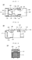
- Fig. 1 is a plan view of the electric connector with a locking mechanism of the first embodiment.
- Fig. 2 is a side view of the above-mentioned electric connector with a locking mechanism.
- Fig. 3 is a front view of the above-mentioned electric connector with a locking mechanism.
- Fig. 4 is an exploded perspective view of the above-mentioned electric connector with a locking mechanism.
- Fig. 5 is an exploded perspective view of the above-mentioned electric connector with a locking mechanism seen from a different angle.
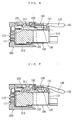
- Fig. 6 is a sectional view of the body of the above-mentioned electric connector with a locking mechanism being inserted in the receiving recess of a counterpart electric connector.
- Fig. 7 is a sectional view of the body of the above-mentioned electric connector with a locking mechanism being withdrawn from the receiving recess of the counterpart electric connector.
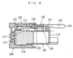
- Fig. 8 is a sectional view of the body of the electric connector with a locking mechanism of the second embodiment being inserted in the receiving recess of a counterpart electric connector.
- Fig. 1 through Fig. 5 show an electric connector with a locking mechanism 100 of the first embodiment.
- this electric connector with a locking mechanism 100 female contacts are arranged sidewise as well as vertically to form a multiple layers.
- the present invention is applicable to an electric connector having male contacts.
- the number or arrangement of contacts of the electric connector with a locking mechanism according to the present invention is not limited in any way by this embodiment.
- the above-mentioned electric connector with a locking mechanism 100 is provided with a body 110 which can be inserted into the receiving recess 210 of a counterpart electric connector 200.
- the receiving recess 210 is concavely formed in the counterpart electric connector 200, and the above-mentioned body 110 is formed into a configuration which corresponds to the internal space of the receiving recess 210.
- the insertion of the body 110 of the electric connector with a locking mechanism 100 into the receiving recess 210 of the counterpart electric connector 200 connects the electric connector with a locking mechanism 100 with the counterpart electric connector 200, with each pair of corresponding contacts of the former and the latter contacting with each other.
- the withdrawal of the body 110 of the electric connector with a locking mechanism 100 from the receiving recess 210 of the counterpart electric connector 200 disconnects the electric connector with a locking mechanism 100 from the counterpart electric connector 200, with each pair of the corresponding contacts being disconnected from each other.
- the direction of shifting of the body 110 or the receiving recess 210 at the time of insertion or withdrawal is defined as the direction of insertion and withdrawal, and is called the insertion/withdrawal direction for short.
- the body 110 is provided with cells of which number is equal to the number of poles, with each cell opening in the front wall 111 of the body 110 and holding a contact (not illustrated). Contacts to contact with those of the body 110 are provided deep in the receiving recess 210 of the counterpart electric connector 200 (not illustrated).
- the above-mentioned body 110 is provided with a flexible arm 120. Its flexibility is accomplished by, for example, molding the arm 120 with a resin or the like.
- the arm 120 extends outside the body 110 in the insertion/withdrawal direction, with the root end 121 of the arm being provided on a side wall 112 of the body 110.
- the side wall 112 of the body 110 is a wall extending from the outer edge of the front wall 111 of the body 110 to the rear face 113 of the body 110 almost in the insertion/withdrawal direction.
- the root end 121 of the arm 120 may be provided integrally with the side wall 112 of the body 110 or fixed onto the side wall 112 by the fit-in method or any other method.
- the arm 120 is provided with protrusions 122, which rise in a direction of moving away from the side wall 112 and fit into fitting holes 211 of the receiving recess 210 of the counterpart electric connector 200. These protrusions 122 are provided closer to the top end of the arm 120 rather than to the root end 121 thereof.
- the fitting holes 211 of the counterpart electric connector 200 are provided in a wall which is one of the walls comprising the receiving recess 210 and faces the side wall 112 of the body 110 when the body 110 of the electric connector with a locking mechanism 100 is inserted in the receiving recess 210.
- Each fitting hole 211 may be a hole with a bottom or a through hole.
- the above-mentioned body 110 is provided with a slider 130.
- the slider 130 is provided in such a way that it extends outside the body 110 in the insertion/withdrawal direction and at least a part thereof overlaps with the arm 120 in the direction of going away from the side wall 112 of the body 110.
- the arm 120 rather than the slider 130, is arranged to be closer to the side wall 112, but their relationship may be reversed.
- the slider 130 is provided on the body 110 in such a way that it can slide in the insertion/withdraw direction.
- both the body 110 and the slider 130 have planes which are almost parallel to the side wall 112 of the body 110, and the body 110 and the slider 130 can contact with and slide against each other by means of these planes, and the slider 130 is held to prevent it from coming off the body 110.
- a direction substantially perpendicular to the insertion/withdrawal direction is defined as the width direction, and support members 114 rise from the side wall 112 to face each other across the arm 120 in the width direction of the body 110.
- Each support member 114 is provided with a support piece 114a which is substantially parallel to the side wall 112 and extends in the insertion/withdrawal direction.
- the slider 130 is provided, on both edges thereof in the width direction, with supported pieces 131 protruding in the width direction.
- Each supported piece 131 rather than the support piece 114a of the corresponding support member 114, is located closer to the side wall 112.
- the outer face of the supported piece 131 being the far side thereof from the side wall 112 contacts with the inner face of the support piece 114a being the near side thereof to the side wall 112.
- the slider 130 can slide over the body 110 in the insertion/withdrawal direction through the sliding of the two faces.
- the above-mentioned arm 120 or the above-mentioned body 110 is provided with an operating lever 140 in such a way that the operating lever 140 can rotate on an axis of rotation 141 extending in the width direction.
- the axis of rotation 141 is provided at the root end 121 of the arm 120, and the operating lever 140 is provided with bearing members which rotatably fit on the axis of rotation 141 from outside.
- the axis of rotation may be provided on the body rather than the arm.
- the axis of rotation may be provided on the operating lever and the parts to fit on the axis of rotation may be provided on the arm or the body, respectively.
- the top end 142 of the operating lever 140 protrudes from the rear face of the body 110, and the operating lever 140 is coupled with the slider 130 so that when the operating lever 140 is rotated, the slider will be slid.
- the axis of rotation 141 is closer to the side wall 113 than the coupling section between the operating lever 140 and the slider 130, and due to this offset, when the operating lever 140 is rotated, the slider 130 will be slid.
- At least one of the arm 120 and the slider 130 is provided with a cam face which is inclined in such a way that its distance from the side wall 112 of the body 110 changes along the insertion/withdraw direction, and flexes the arm 120 according to the sliding of the slider 130 so as to bring the protrusions 122 closer to the side wall 112 of the body 110.
- cam faces are provided on both the arm 120 and the slider 130. The cam face 123 of the arm 120 is located closer to the side wall 112 of the body 110 than the cam face 132 of the slider 130, and these cam faces have a face-contact with each other.
- the cam faces 123 and 132 are inclined in such a way that their distances from the side wall 112 of the body 110 increase along the insertion/withdrawal direction from the front wall 111 of the body 110 towards the rear face 113 thereof. Accordingly, when the slider 130 slides in the insertion/withdrawal direction from the front wall 111 of the body 110 towards the rear face 113 thereof, the cam face 123 of the arm 120 will be pressed by the cam face 132 of the slider 130, and as the slider 130 does not move in the direction of going away from the side wall 112, the arm 120 will be flexed to get closer relatively towards the side wall 112. As a result, the protrusions 122 will get closer to the side wall 112 of the body 110.
- the operating lever 140 extends outside the body 110 almost in the insertion/withdrawal direction.
- the axis of rotation 141 is closer to the side wall 112 of the body 110 than the slider 130, and as shown in Fig. 7, the configuration is such that when the top end 142 is rotated towards the rear face 113 of the body 110, the slider 130 will be slid to bring the protrusions 122 closer to the side wall 112 of the body 110.
- the operating lever 140 and the slider 130 are coupled together by integrally molding them with a flexible material such as resin.
- the slider 130 will be slid, and due to the guiding functions of the cam faces 123 and 132, the arm 120 will be flexed to move the protrusions 122 closer to the side wall 112 of the body 110.
- the protrusions 122 will come out of the fitting holes 211 of the receiving recess 210 of the counterpart electric connector 200, allowing the withdrawal of the electric connector with a locking mechanism 100.
- the amount of operation and the operation resistance of the operating lever 140 can be freely set by changing, for example, the distance from the root end 121 of the arm 120 to the protrusions 122, the distance from the root end 121 to the cam face 123, or the inclinations of the cam faces 123 and 132.
- the present invention includes embodiments wherein a cam face is provided at least one of the arm and the slider. Accordingly, the present invention includes embodiments wherein a cam face is provided on either the arm or the slider, and the other one is provided with a part which contacts with the cam face and is guided by the cam face.
- the amount of operation and the operation resistance of the operating lever can be freely set by changing the distance from the root end of the arm to the protrusions, the distance from the root end to the cam face or the part contacting with the cam face, the inclination of the cam face, etc.
- cam faces 123 and 132 are provided on both the arm 120 and the slider 130, and these cam faces are made to have a face-contact with each other.
- the present invention includes all embodiments wherein the operating lever is rotatably provided on the body so that the top end of the operating lever protrudes from the rear face of the body and the operating lever is coupled with the slider so that when the operating lever is rotated, the slider will be slid.
- the configuration is such that the operating lever 140 extends outside the body 110 almost in the insertion/withdrawal direction, the axis of rotation 141 is located closer to the side wall 112 of the body 110 than the slider 130, and when the top end 142 is rotated towards the rear face 113 of the body 110, the slider 130 will be slid to bring the protrusions 122 closer to the side wall 112 of the body 110.
- the operating lever 140 can be kept almost within the space directly behind the body 110 in the insertion/withdrawal direction.
- the operating lever 140 can be operated even when there is no space around the body 110 except said space directly behind the body 110 in the insertion/withdrawal direction. This is convenient, for example, when the invention is used for an electric connector with a locking mechanism wherein contacts are arranged in multiple layers.
- the present invention includes all embodiments wherein the operating lever and the slider are provided as separate members.
- the operating lever 140 and the slider 130 are coupled together by integrally molding them with a flexible material. With this arrangement, the number of parts is reduced and, in turn, the number of control processes is reduced, and the productivity is enhanced through integral molding.
- Fig. 8 shows the second embodiment.
- the root end 121 of the arm 120 is located on the arm 120 at a point close to the rear face 113 of the body 110.
- the root end 121 of the arm 120 is located on the arm 120 at a point close to the front wall 111 of the body 110. Its operation and effects are similar to those of the first embodiment.
- the second electric connector with a locking mechanism is the first electric connector with a locking mechanism wherein cam faces are provided on both the arm and the slider and these cam faces are in face-contact with each other.
- the third electric connector with a locking mechanism is the first electric connector with a locking mechanism or the second electric connector with a locking mechanism, wherein the configuration is such that the operating lever extends outside the body almost in the insertion/withdrawal direction, the axis of rotation is located closer to the side wall of the body than the slider, and when the top end is rotated towards the rear face of the body, the slider will be slid to bring the protrusion closer to the side wall of the body.
- the operating lever can be kept almost within the space directly behind the body in the insertion/withdrawal direction. Hence the operating lever can be operated even when there is no space around the body except said space directly behind the body in the insertion/withdrawal direction. This is convenient, for example, when the invention is used for an electric connector with a locking mechanism wherein contacts are arranged in multiple layers.
- the fourth electric connector with a locking mechanism is any one of the first electric connector with a locking mechanism through the third electric connector with a locking mechanism, wherein the operating lever and the slider are coupled together by integrally molding them with a flexible material.
Landscapes
- Details Of Connecting Devices For Male And Female Coupling (AREA)
- Coupling Device And Connection With Printed Circuit (AREA)
Abstract
Description
Claims (4)
- An electric connector (100) with a locking mechanism comprising
a body (110) to be inserted into a receiving recess (210) of a counterpart electric connector (200),
a flexible arm (120), of which root end (121) is provided on a side wall (112) of the body (110), said flexible arm (120) extending outside the body (110) in the direction of insertion and withdrawal and being provided with a protrusion (122), which rises in a direction of going away from the side wall (112) of the body (110) and fits into a fitting hole (211) of the receiving recess (210) of the counterpart electric connector (200),
a slider (130) being provided in such a way that it extends outside the body (110) in the direction of insertion and withdrawal, overlaps with the arm (120) in the direction of going away from the side wall (112) of the body (110) and can slide over the body (110) in the direction of insertion and withdrawal, and
an operating lever (140) being rotatably provided on the arm (120) or the body (110) in such a way that the top end (142) thereof comes out on the rear face side of the body (110) and being coupled with the slider (130) in such a way that when the operating lever (140) is rotated, the slider (130) will be slid,
at least either said arm (120) or said slider (130) being provided with a cam face (123),(132) which is inclined in such a way that its distance from the side wall (112) of the body (110) changes along the direction of insertion and withdrawal and makes the arm (120) flex according to the sliding of the slider (130) so that the protrusion (122) come closer to the side wall (112) of the body (110). - An electric connector (100) with a locking mechanism as recited in claim 1,
wherein cam faces (123),(132) are provided on both the arm (120) and the slider (130) and these cam faces (123),(132) make a face-contact with each other. - An electric connector (100) with a locking mechanism as recited in claim 1 or claim 2,
wherein the configuration is such that the operating lever (140) extends outside the body (110) almost in the insertion/withdrawal direction, the axis (141) of rotation is located closer to the side wall (112) of the body (110) than the slider (130), and when the top end (142) is rotated towards the rear face (113) of the body (110), the slider (130) will be slid to bring the protrusion (122) closer to the side wall (112) of the body (110). - An electric connector (100) with a locking mechanism as recited in any of the claims 1 to 3,
wherein the operating lever (140) and the slider (130) are coupled together by integrally molding them with a flexible material.
Applications Claiming Priority (2)
| Application Number | Priority Date | Filing Date | Title |
|---|---|---|---|
| JP2002024720 | 2002-01-31 | ||
| JP2002024720A JP3609379B2 (en) | 2002-01-31 | 2002-01-31 | Electrical connector with locking mechanism |
Publications (3)
| Publication Number | Publication Date |
|---|---|
| EP1333543A2 true EP1333543A2 (en) | 2003-08-06 |
| EP1333543A3 EP1333543A3 (en) | 2004-12-08 |
| EP1333543B1 EP1333543B1 (en) | 2006-12-13 |
Family
ID=19192288
Family Applications (1)
| Application Number | Title | Priority Date | Filing Date |
|---|---|---|---|
| EP03001857A Expired - Lifetime EP1333543B1 (en) | 2002-01-31 | 2003-01-29 | Electric connector with a locking mechanism |
Country Status (7)
| Country | Link |
|---|---|
| US (1) | US6692289B2 (en) |
| EP (1) | EP1333543B1 (en) |
| JP (1) | JP3609379B2 (en) |
| KR (1) | KR100913131B1 (en) |
| CN (1) | CN1311591C (en) |
| DE (1) | DE60310279T2 (en) |
| TW (1) | TWI273748B (en) |
Cited By (1)
| Publication number | Priority date | Publication date | Assignee | Title |
|---|---|---|---|---|
| CN100344032C (en) * | 2003-12-05 | 2007-10-17 | 住友电装株式会社 | Connector locking construction, connector and connector assembly |
Families Citing this family (41)
| Publication number | Priority date | Publication date | Assignee | Title |
|---|---|---|---|---|
| JP2005209407A (en) * | 2004-01-20 | 2005-08-04 | Jst Mfg Co Ltd | Connector with locking mechanism |
| USD554068S1 (en) * | 2004-09-15 | 2007-10-30 | 3M Innovative Properties Company | Cap for an electrical connector |
| JP3996168B2 (en) * | 2005-02-28 | 2007-10-24 | タイコエレクトロニクスアンプ株式会社 | Connector boot and connector assembly |
| US7465185B2 (en) * | 2006-03-30 | 2008-12-16 | Fci Americas Technology, Inc | Electrical connector assembly with mate-assist and a wire dress cover |
| US7207823B1 (en) * | 2006-04-18 | 2007-04-24 | All Best Electronics Co., Ltd. | Plug connector |
| US7226307B1 (en) * | 2006-07-27 | 2007-06-05 | Jess-Link Products Co., Ltd. | Plug connector |
| JP4755056B2 (en) * | 2006-09-15 | 2011-08-24 | 日本圧着端子製造株式会社 | connector |
| US7651361B2 (en) | 2008-04-30 | 2010-01-26 | Tyco Electronics Corporation | Electrical connector having pull tether for latch release |
| US7682181B1 (en) * | 2008-09-09 | 2010-03-23 | Tyco Electronics Corporation | Latch securing member |
| ES2402632B1 (en) | 2011-02-08 | 2014-05-14 | Tyco Electronics Raychem Bvba | RELEASE TONGUE FOR AN ELECTRICAL CONNECTOR AND ELECTRICAL CONNECTOR THAT INCLUDES SUCH RELEASE TONGUE |
| ES2395358B1 (en) | 2011-02-08 | 2014-04-25 | Tyco Electronics Corporation | SINGLE ACTION CONNECTOR |
| CN103094780A (en) * | 2011-11-04 | 2013-05-08 | 富士康(昆山)电脑接插件有限公司 | plug connector |
| CN103257407B (en) | 2012-02-20 | 2015-11-25 | 泰科电子(上海)有限公司 | Connector and connector assembly |
| JP5748692B2 (en) * | 2012-03-08 | 2015-07-15 | ヒロセ電機株式会社 | Electrical connector |
| CN103996929B (en) * | 2013-02-18 | 2016-09-21 | 中航光电科技股份有限公司 | Anti-error de-plug and use the electric coupler component of this plug |
| JP5885096B2 (en) * | 2013-05-08 | 2016-03-15 | 住友電装株式会社 | connector |
| EP3095000B1 (en) | 2014-01-13 | 2021-04-28 | CommScope Telecommunications (Shanghai) Co. Ltd. | Fiber optic connector |
| EP3046185B1 (en) * | 2015-01-13 | 2024-01-24 | Tyco Electronics AMP Korea Co., Ltd. | Connector |
| JP6249998B2 (en) * | 2015-07-06 | 2017-12-20 | 矢崎総業株式会社 | connector |
| DE102016102071B3 (en) * | 2016-02-05 | 2017-06-08 | Wago Verwaltungsgesellschaft Mbh | Electrical connector assembly and release element for this purpose |
| CN105977703A (en) * | 2016-07-21 | 2016-09-28 | 郑静 | Interface equipment used for electric power |
| JP6857073B2 (en) * | 2017-04-07 | 2021-04-14 | モレックス エルエルシー | Connector and connector assembly |
| WO2018226959A1 (en) | 2017-06-07 | 2018-12-13 | Commscope Technologies Llc | Fiber optic adapter and cassette |
| EP3639330B1 (en) | 2017-06-13 | 2025-03-26 | Samtec Inc. | Electrical cable connector |
| CN111262077B (en) * | 2017-06-23 | 2022-01-14 | 上海莫仕连接器有限公司 | Power supply connector |
| USD877700S1 (en) | 2017-07-17 | 2020-03-10 | Samtec, Inc. | Electrical connector |
| USD877084S1 (en) | 2017-07-17 | 2020-03-03 | Samtec, Inc. | Electrical connector |
| WO2019018728A1 (en) * | 2017-07-21 | 2019-01-24 | Samtec Inc. | Electrical connector having latch |
| USD964291S1 (en) | 2017-07-21 | 2022-09-20 | Samtec, Inc. | Electrical connector |
| USD823814S1 (en) | 2017-07-24 | 2018-07-24 | Samtec, Inc. | Contact wafer |
| WO2019055820A1 (en) | 2017-09-15 | 2019-03-21 | Commscope Technologies Llc | Fiber optic connector with boot-integrated release and related assemblies |
| US11495917B2 (en) | 2017-10-24 | 2022-11-08 | Samtec, Inc. | Right-angle electrical connector and electrical contacts for a right-angle connector |
| USD896183S1 (en) | 2018-01-08 | 2020-09-15 | Samtec, Inc. | Electrical cable connector |
| DE102018102011B4 (en) * | 2018-01-30 | 2020-07-02 | Wago Verwaltungsgesellschaft Mbh | Electrical connector |
| DE102018010384B4 (en) | 2018-01-30 | 2024-06-27 | Wago Verwaltungsgesellschaft Mbh | Electrical connector |
| CN110323630B (en) * | 2018-03-30 | 2020-10-30 | 中航光电科技股份有限公司 | Locking structure and connector housing and connector with the same |
| USD881133S1 (en) | 2018-12-20 | 2020-04-14 | Samtec, Inc. | Contact wafer |
| DE102019116140B3 (en) * | 2019-06-13 | 2020-10-15 | ept Holding GmbH & Co. KG | Cable connector with locking lever |
| CN115698800A (en) | 2020-05-29 | 2023-02-03 | 康普技术有限责任公司 | Telecommunications connectors with latch release mechanism |
| WO2022216861A1 (en) | 2021-04-08 | 2022-10-13 | Commscope Technologies Llc | Telecommunications connector with latch release mechanism |
| JP2022181590A (en) * | 2021-05-26 | 2022-12-08 | タイコエレクトロニクスジャパン合同会社 | Connector with lever and connector system comprising connector with lever |
Family Cites Families (16)
| Publication number | Priority date | Publication date | Assignee | Title |
|---|---|---|---|---|
| JPS59230271A (en) * | 1983-06-13 | 1984-12-24 | 富士通株式会社 | Connector |
| JPS62163276A (en) * | 1985-10-07 | 1987-07-20 | ト−マス アンド ベツツ コ−ポレ−シヨン | Latching apparatus |
| US4711507A (en) * | 1985-10-07 | 1987-12-08 | Thomas & Betts Corporation | Electrical connector and latching apparatus therefor |
| JPS6265779U (en) * | 1985-10-12 | 1987-04-23 | ||
| NL8901438A (en) * | 1989-06-06 | 1991-01-02 | Du Pont Nederland | CONNECTOR. |
| JPH0755830Y2 (en) * | 1990-09-18 | 1995-12-20 | ヒロセ電機株式会社 | Connector lock eject mechanism |
| JP2864954B2 (en) * | 1993-07-28 | 1999-03-08 | 住友電装株式会社 | connector |
| JP2970347B2 (en) * | 1993-09-28 | 1999-11-02 | 住友電装株式会社 | connector |
| JP2600949Y2 (en) * | 1993-12-16 | 1999-11-02 | ヒロセ電機株式会社 | Electrical connector for circuit board insertion |
| EP0760542B1 (en) * | 1995-08-26 | 2002-02-27 | Molex Incorporated | Electrical connector with improved latching system |
| GB2308755B (en) * | 1995-12-28 | 1997-12-17 | Yazaki Corp | Half-fitting prevention connector |
| JPH10321292A (en) | 1997-05-16 | 1998-12-04 | Sumitomo Wiring Syst Ltd | Connector |
| JP3529019B2 (en) | 1997-10-24 | 2004-05-24 | 矢崎総業株式会社 | Connector with holder |
| JP3538750B2 (en) * | 1999-08-02 | 2004-06-14 | 住友電装株式会社 | Lever type connector |
| US6254418B1 (en) * | 2000-08-16 | 2001-07-03 | The Jpm Company | Latch release |
| US6450830B1 (en) * | 2001-06-25 | 2002-09-17 | Hon Hai Precision Ind. Co., Ltd. | Electrical connector having improved latching means |
-
2002
- 2002-01-31 JP JP2002024720A patent/JP3609379B2/en not_active Expired - Fee Related
- 2002-12-27 TW TW091137728A patent/TWI273748B/en not_active IP Right Cessation
-
2003
- 2003-01-06 KR KR1020030000493A patent/KR100913131B1/en not_active Expired - Fee Related
- 2003-01-28 US US10/353,361 patent/US6692289B2/en not_active Expired - Fee Related
- 2003-01-29 DE DE60310279T patent/DE60310279T2/en not_active Expired - Lifetime
- 2003-01-29 EP EP03001857A patent/EP1333543B1/en not_active Expired - Lifetime
- 2003-01-31 CN CNB031031579A patent/CN1311591C/en not_active Expired - Fee Related
Cited By (1)
| Publication number | Priority date | Publication date | Assignee | Title |
|---|---|---|---|---|
| CN100344032C (en) * | 2003-12-05 | 2007-10-17 | 住友电装株式会社 | Connector locking construction, connector and connector assembly |
Also Published As
| Publication number | Publication date |
|---|---|
| JP3609379B2 (en) | 2005-01-12 |
| CN1435920A (en) | 2003-08-13 |
| KR100913131B1 (en) | 2009-08-19 |
| HK1057653A1 (en) | 2004-04-08 |
| JP2003229209A (en) | 2003-08-15 |
| DE60310279T2 (en) | 2007-04-12 |
| TW200302607A (en) | 2003-08-01 |
| US20030143886A1 (en) | 2003-07-31 |
| CN1311591C (en) | 2007-04-18 |
| TWI273748B (en) | 2007-02-11 |
| DE60310279D1 (en) | 2007-01-25 |
| EP1333543A3 (en) | 2004-12-08 |
| EP1333543B1 (en) | 2006-12-13 |
| US6692289B2 (en) | 2004-02-17 |
| KR20030065316A (en) | 2003-08-06 |
Similar Documents
| Publication | Publication Date | Title |
|---|---|---|
| US6692289B2 (en) | Electric connector with a locking mechanism | |
| EP0938162B1 (en) | Two-part electrical connector | |
| EP1830436B1 (en) | A connector, connector assembly and assembling method | |
| US6644992B2 (en) | Lever-type connector | |
| US7357663B2 (en) | Electrical connector with latching member | |
| US7520765B2 (en) | Connector and connector assembly of the movable member type | |
| US6764324B2 (en) | Lever-type connector assembly | |
| US8992240B2 (en) | Connector | |
| CN105308797A (en) | Cable connector | |
| US6939163B2 (en) | Connector | |
| US7044806B2 (en) | Electrical connector terminal position assurance polarization | |
| US20190296484A1 (en) | Lever-type connector | |
| US20020081912A1 (en) | Connector | |
| US6896560B2 (en) | Connector with retainer having front wall and reinforcement | |
| WO1997011515A1 (en) | Electrical connector having double-lock member | |
| US7445474B2 (en) | Lever-type connector and lever-type connector assembly | |
| JP2008204663A (en) | Lever connector | |
| CN118676682A (en) | Matching structure | |
| JP4175774B2 (en) | connector | |
| JP4863823B2 (en) | Connector lock structure | |
| JP2000195617A (en) | Connector | |
| US8403713B2 (en) | Connector with dedicated locks and engaging portions | |
| JP2004241315A (en) | Connector holder | |
| JP2003229198A (en) | Connector | |
| JPH069073U (en) | connector |
Legal Events
| Date | Code | Title | Description |
|---|---|---|---|
| PUAI | Public reference made under article 153(3) epc to a published international application that has entered the european phase |
Free format text: ORIGINAL CODE: 0009012 |
|
| AK | Designated contracting states |
Designated state(s): AT BE BG CH CY CZ DE DK EE ES FI FR GB GR HU IE IT LI LU MC NL PT SE SI SK TR |
|
| AX | Request for extension of the european patent |
Extension state: AL LT LV MK RO |
|
| PUAL | Search report despatched |
Free format text: ORIGINAL CODE: 0009013 |
|
| AK | Designated contracting states |
Kind code of ref document: A3 Designated state(s): AT BE BG CH CY CZ DE DK EE ES FI FR GB GR HU IE IT LI LU MC NL PT SE SI SK TR |
|
| AX | Request for extension of the european patent |
Extension state: AL LT LV MK RO |
|
| 17P | Request for examination filed |
Effective date: 20050418 |
|
| 17Q | First examination report despatched |
Effective date: 20050704 |
|
| AKX | Designation fees paid |
Designated state(s): DE FR GB |
|
| GRAP | Despatch of communication of intention to grant a patent |
Free format text: ORIGINAL CODE: EPIDOSNIGR1 |
|
| GRAS | Grant fee paid |
Free format text: ORIGINAL CODE: EPIDOSNIGR3 |
|
| GRAA | (expected) grant |
Free format text: ORIGINAL CODE: 0009210 |
|
| AK | Designated contracting states |
Kind code of ref document: B1 Designated state(s): DE FR GB |
|
| REG | Reference to a national code |
Ref country code: GB Ref legal event code: FG4D |
|
| REF | Corresponds to: |
Ref document number: 60310279 Country of ref document: DE Date of ref document: 20070125 Kind code of ref document: P |
|
| ET | Fr: translation filed | ||
| PLBE | No opposition filed within time limit |
Free format text: ORIGINAL CODE: 0009261 |
|
| STAA | Information on the status of an ep patent application or granted ep patent |
Free format text: STATUS: NO OPPOSITION FILED WITHIN TIME LIMIT |
|
| 26N | No opposition filed |
Effective date: 20070914 |
|
| PGFP | Annual fee paid to national office [announced via postgrant information from national office to epo] |
Ref country code: DE Payment date: 20110127 Year of fee payment: 9 Ref country code: FR Payment date: 20110201 Year of fee payment: 9 |
|
| PGFP | Annual fee paid to national office [announced via postgrant information from national office to epo] |
Ref country code: GB Payment date: 20110121 Year of fee payment: 9 |
|
| GBPC | Gb: european patent ceased through non-payment of renewal fee |
Effective date: 20120129 |
|
| REG | Reference to a national code |
Ref country code: FR Ref legal event code: ST Effective date: 20120928 |
|
| PG25 | Lapsed in a contracting state [announced via postgrant information from national office to epo] |
Ref country code: DE Free format text: LAPSE BECAUSE OF NON-PAYMENT OF DUE FEES Effective date: 20120801 Ref country code: GB Free format text: LAPSE BECAUSE OF NON-PAYMENT OF DUE FEES Effective date: 20120129 |
|
| REG | Reference to a national code |
Ref country code: DE Ref legal event code: R119 Ref document number: 60310279 Country of ref document: DE Effective date: 20120801 |
|
| PG25 | Lapsed in a contracting state [announced via postgrant information from national office to epo] |
Ref country code: FR Free format text: LAPSE BECAUSE OF NON-PAYMENT OF DUE FEES Effective date: 20120131 |