BACKGROUND OF THE INVENTION
Field of the Invention
-
The present invention relates to a display screen
operation device which is applied to various kinds of devices,
such as a car navigation device and an audio device of a vehicle,
in which various kinds of operations are executed under
confirmation of a display screen as a monitor.
Description of the Related Art
-
Recently, there has been a vehicle which is provided with
a monitor having a monitoring display screen on an instrument
panel or in a housing section formed in the instrument panel
of the vehicle, and in which, for example, a map display screen
and the like is displayed on the monitoring display screen of
the car navigation device.
-
Moreover, since various kinds of devices such as an audio
device and an air-conditioning device as well as the above-described
car navigation device are installed on the vehicle,
a configuration is also being considered, for example, in which
a virtual control panel comprising icons, which correspond to
each of various kinds of devices, and the like is displayed on
the display screen of the monitor, a display screen of the
monitor is switched to a virtual control panel corresponding
to a desired device, using a controller, and a pointer or the
like displayed on the display screen of the monitor is moved
onto an icon, which corresponds to the contents of a desired
control or operation, using the controller, to select the icon
in order to execute the desired control or operation.
-
In such a configuration, there is an advantage that one
controller can operate and control various kinds of devices even
when the number of devices installed in the vehicle is
increased.
-
On the other hand, controllers used for the above devices
include one having a configuration in which a touch panel is
provided in a part of the main body of the controller.
-
That is, according to the configuration, a coordinate
position on the touch panel of the controller is set in
correspondence to a coordinate position on the display screen
of the monitor to move a finger and the like on the touch panel
and to move a pointer displayed on the display screen of the
monitor.
-
Here, when the above-described controller is operated,
for example, in a moving vehicle, a pointer is sometimes
slightly moved on the display screen of the monitor, following
the movement of a finger on the touch panel due to vibration
of the vehicle. As a result, for example, the following
situations occur: the pointer is located on an icon which is
not intended to be selected, and the icon is put into a selected
state (for example, the color of the icon is changed) ; and the
pointer frequently moves among a plurality of icons in a short
time, and a plurality of icons are alternately put into the
selected state in a short time.
-
In order to prevent the above disadvantages, a
configuration (refer to Japanese Patent Application Laid-Open
(JP-A) No. 11-127399 as one example) has been considered in
which a gray zone is set between adjoining icons, and the
existing selected state of an icon is not released (not
cancelled) when the pointer is located within a predetermined
range even if the pointer deviates from the icon.
-
However, when the gray zone is set as described above,
there occurs a phenomenon that the selected state is maintained
though a finger position on the touch panel is greatly away from
the selected icon. Since such a phenomenon causes an unnatural
feeling that operational feeling on the touch panel does not
correspond to the state of the display screen of the monitor,
there is much room for improvement from the viewpoint of the
operability.
-
Especially, for example, when vibration in the vehicle
is extremely slight, for example, when the vehicle is stopped,
and movement of a finger on the touch panel is basically small,
the above described problems are much less liable to occur, but,
instead, the above described unnatural feeling becomes large.
SUMMARY OF THE INVENTION
-
An object of the present invention is to provide a display
screen operation device which causes less unnatural feeling at
operation and has high operability.
-
A first aspect of the invention provides a display screen
operation device comprising: an operation unit which transmits
an operation signal including position information according
to a position on a display screen of a monitor by a predetermined
operation; and a control unit which is connected to the monitor,
displays a plurality of selection sections at predetermined
positions on the display screen, puts the selection section into
a selected state when the position information of the operation
signal sent from the operation unit is corresponding to any one
of the plurality of selection sections in a display state of
the plurality of selection sections, sets a release area at a
position away from each of the plurality of selection sections
on the display screen and, between the plurality of selection
sections, and releases the selected state when the operation
signal including the position information corresponding to the
inside of the release area is received in the selected state,
or, when the operation signal including the position
information corresponding to an area other than the release area
is received.
-
In the display screen operation device with the above
configuration, a plurality of selection sections are displayed
on a display screen of the monitor by the control unit. When
the operation unit is operated, and an operation signal is sent
to the control unit under such a condition, relevant selection
section is put into a selected state in the control unit if
position information included in the operation signal is
corresponding to positions of any of selection sections on the
display screen of the monitor.
-
Incidentally, release areas are set on the display screen
of the monitor by the control unit under a state in which a
plurality of selection sections are displayed on the display
screen of the monitor. The release areas are set at positions
away from each of the plurality of selection sections on the
display screen of the monitor and between the plurality of
selection sections.
-
Here, when an operation signal including position
information corresponding to positions in the release area, or
an operation signal including position information
corresponding to an area other than the release area is sent
from the operation unit to the control unit under a state in
which any of the plurality of selection sections are selected,
the above selected state is released by the control unit.
-
Thereby, there is caused no feeling of difference between
operations of the operation unit and display on the display
screen of the monitor, that is, the selection sections at
positions away from the positions corresponding to the position
information in the operation signal are still in the selected
state. Therefore, the screen display corresponding to the
operational feeling can be realized to improve the operability.
-
A second aspect of the invention provides a display screen
operation device comprising: an operation unit which transmits
an operation signal including position information according
to a position on a display screen of a monitor by a predetermined
operation; and a control unit which is connected to the monitor,
displays a plurality of selection sections at predetermined
position on the display screen, put the selection section into
a selected state when the position information of the operation
signal sent from the operation unit is corresponding to any one
of the plurality of selection sections in a display state of
the plurality of selection sections, set a maintenance area in
a predetermined range on the display screen including any one
of the plurality of selection sections inside the range,
corresponding to each of the plurality of selection sections,
maintains the state of the display screen in a state before
receiving the operation signal when the position information
of the operation signal from the operation unit is corresponding
to a position within the maintenance area and excluding the
selection sections with in the maintenance area, and, further,
changes the setting range of the maintenance area based on
predetermined conditions.
-
In the display screen operation device with the above
configuration, a plurality of selection sections are displayed
on a display screen of the monitor by the control unit. When
the operation unit is operated, and an operation signal is sent
to the control unit under such a condition, relevant selection
section iss put into a selected state in the control unit if
position information included in the operation signal is
corresponding to positions of any of selection sections on the
display screen of the monitor.
-
Incidentally, a plurality of maintenance areas are set
on the display screen of the monitor by the control unit under
a state in which a plurality of selection sections are displayed
on the display screen of the monitor. Each of the maintenance
areas are set corresponding to each of the plurality of
selection sections, and include the corresponding selection
sections within the areas (that is, the maintenance areas are
set on the peripheries of the corresponding selection
sections).
-
When the control unit receives an operation signal having
position information corresponding to positions within the
maintenance areas except the corresponding selection sections,
the display state of the display screen of the monitor is
maintained by the control unit in a state before the operation
signal is received.
-
Thereby, even when an operation signal including position
information on positions, which are away from the selection
sections due to ambiguous operations or small movements of a
finger, has been transmitted immediately after any of the
selection sections are selected by operation of the operation
unit, the selected states of the selection sections do not
change. Thereby, the operability is improved, as careful and
strict operation is not required at operation of the operation
unit.
-
Here, the sizes of the maintenance areas are changed,
based on predetermined conditions, in the display screen
operation device.
-
Therefore, it is possible by reducing the sizes of the
maintenance areas to properly change the display state of the
display screen of the monitor according to change in the
operation of the operation unit (that is, selection, release,
and switching of the selection sections) under a state in which
it is difficult to cause ambiguous operation of the operation
unit or small movements of a finger. Thereby, the operability
is improved.
-
Also, for example, when an environment at operation of
the operation unit is a place (for example, in a room of a vehicle
under running) in which devices are comparatively easily
vibrated, release of selected states of selection sections and
the like, which is caused by unintentional operation of the
operation unit in an environment in which devices are easily
vibrated, may be prevented by enlarging the sizes of the
maintenance areas. From the above reason, the operability is
improved.
-
A third aspect of the invention provides a display screen
operation device, according to the first aspect, comprising:
a notification signal transmission unit which is operated when
the control unit receives the operation signal including the
position information corresponding to a position at a
predetermined distance away from the selection section on the
display screen, and transmits a predetermined notification
signal.
-
In the display screen operation device with the
above-described configuration, when position information on an
operation signal which the control unit received from the
operation unit is one corresponding to positions at a
predetermined range away from the selection sections on the
display screen of the monitor, the notification signal
transmission unit transmits a predetermined notification
signal, which can be recognized by any one of the five senses,
such as light, sound, and vibration, of a user. Thereby,
operation results by the operation unit may be understood
without careful watching of the display screen of the monitor.
-
Here, though the display screen operation device has a
configuration by which the notification signal transmission
unit transmits a predetermined notification signal, the
notification signal is not limited to forms, such as light,
sound, and vibration (pressure), as described above, if it is
a signal which can be recognized by any one of the five senses
of a user. Also, when the notification signal is light, the
monitor may be also used as the notification signal transmission
unit. Furthermore, when the notification signal is vibration,
pressure, and the like, the notification signal transmission
unit may be provided in the operation unit, if the operation
unit has a basic configuration by which the unit always touches
the body (for example, a palm or a finger) of a user at operation.
-
A fourth aspect of the invention provides a display screen
operation device, according to the third aspect, wherein the
notification signal transmission unit changes the notification
signal gradually or stepwise as the position on the display
screen corresponding to the position information approaches the
selection section.
-
In the display screen operation device with the
above-described configuration, the notification signal is
changed gradually or stepwise as the position on the display
screen of the monitor corresponding to the position information
in the operation unit approaches the selection section.
-
Here, for example, in the case of a notification signal
with no change, it is possible to understand that the operation
unit transmits an operation signal including position
information corresponding to the position at a predetermined
range away from a selection section. However, it is impossible
to understand whether the position information is on a position
very near the selection section, or on a position near the border
of the above-described predetermined range. Accordingly, it
is impossible to understand what kinds of operations of the
operation unit are required for selection of the selection
sections after transmission of the notification signal.
-
However, since, in the display screen operation device,
it is possible to understand by change in the notification
signal the difference between the positions of the selection
sections and the positions on the display screen of the monitor
corresponding to the position information included in the
operation signal, selection of the selection sections can be
realized by using the change in the notification signal as a
clue without careful watching of the display screen of the
monitor. Thereby, the operability is improved.
BRIEF DESCRIPTION OF THE DRAWINGS
-
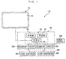
- Fig. 1 is a schematic block diagram showing a
configuration of a display screen operation device according
to a first embodiment of the present invention.
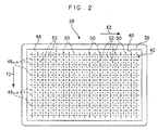
- Fig. 2 is a plan view of a controller as an operation unit.
- Fig. 3 is a development plan view of a touch panel used
as a controller.
- Fig. 4A is a cross section showing a touch panel which
is pressed by a finger aligned generally perpendicular to the
touch panel.
- Fig. 4B is a cross section showing the touch panel which
is pressed by a finger aligned generally parallel to the touch
panel.
- Fig. 5A is a schematic view showing a range on the touch
panel which is pressed by a finger aligned generally
perpendicular to the touch panel.
- Fig. 5B is a schematic view showing a pressed range on
the touch panel which is pressed by a finger aligned generally
parallel to the touch panel.
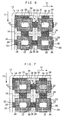
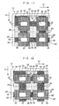
- Fig. 6 is a schematic view showing positions of each area
in a display screen of a monitor.
- Fig. 7 is a view showing a state in which one of selection
sections is selected, and corresponding to Fig. 6.
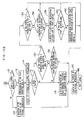
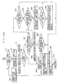
- Fig. 8A and Fig. 8B are schematic flow charts showing
control of the display screen operation device according to the
first embodiment of the invention.
- Fig. 9 is a schematic block diagram showing a
configuration of a display screen operation device according
to a second embodiment of the invention.
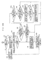
- Fig. 10A and Fig. 10B are schematic flow charts showing
control of the display screen operation device according to the
second embodiment of the invention.
- Fig. 11 is a view showing a state, in which ranges of
maintenance areas and release areas have been changed, and
corresponding to Fig. 6.
- Fig. 12 is a view showing a state, in which the ranges
of the maintenance areas and the release areas have been changed
in a different manner from those of Fig. 11, and corresponding
to Fig. 6.
- Fig. 13 is a schematic block diagram showing a
configuration of a display screen operation device according
to a third embodiment of the invention.
- Fig. 14A and Fig. 14B are schematic flow charts showing
control of the display screen operation device according to the
third embodiment of the invention.
- Fig. 15 is a schematic block diagram showing a
configuration of a display screen operation device according
to a fourth embodiment of the invention.
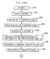
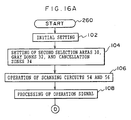
- Fig. 16A and Fig. 16B are schematic flow charts showing
control of the display screen operation device according to the
fourth embodiment of the invention.
- Fig. 17 is a view showing a state, in which a selection
section is put into an intermediate color, and corresponding
to Fig. 6.
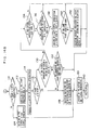
- Fig. 18A and Fig. 18B are schematic flow charts showing
control of the display screen operation device according to the
fifth embodiment of the invention.
-
DETAILED DESCRIPTION OF THE EMBODIMENTS
<Configuration of First Embodiment>
-
Fig. 1 shows a schematic view of a configuration of a
central control device 10 to which a display screen operation
device according to a first embodiment of the present invention
is applied.
-
As shown in Fig. 1, the central control device 10 is
provided with a monitor 12 as a monitor. The monitor 12 is
installed, for example, at a predetermined position on an
instrument panel of a vehicle (not shown), or in a housing hole
formed in the panel in a state that a vehicle crew may see a
display screen 14 with an approximately rectangular shape.
Hereinafter, explanation will be made, assuming for convenience
that the transverse (lengthwise) and right direction is the X1
direction, and the longitudinal (crosswise) and downward
direction of the monitor 12 is the Y1 direction as shown in Fig.
6.
-
Also, as shown in Fig. 1, the monitor 12 is connected to
a control section 16 as a control unit which is provided at an
appropriate position of the vehicle. The control section 16
comprises a computer 24 with a configuration including, for
example, a CPU 18, a RAM 20, and a ROM 22. The control section
16 is configured to control the monitor 12, such that a plurality
of selection buttons (icons) 26 as a selection section which
selects a function and operation contents of the central control
device 10 are displayed on the display screen 14 of the monitor
12 in the directions of X1 and Y1 at a predetermined distance,
as shown in Fig. 6.
-
Also, the computer 24 in the control section 16 displays
a plurality of selection buttons 26 on the display screen 14
of the monitor 12 as described above, and sets an unvisible first
selection area 28 with an approximately rectangular shape on
the display screen 14. A plurality of first selection areas
28 are set, corresponding to each of selection buttons 26, and
are adjacent to each other on the display screen 14. Moreover,
the corresponding selection buttons 26 are located inside of
the areas (for example, approximately at the center),
respectively.
-
In addition, each of the first selection areas 28
comprises: a second selection areas 30 which is unvisible on
the display screen 14; a gray zone 32 as a maintenance area;
and a cancellation zone 34 as a release area. The second
selection area 30 has an approximately rectangular shape
smaller than the first selection area 28, and the corresponding
selection button 26 is located within the area (for example,
approximately at the center).
-
On the other hand, the gray zone 32 touches the second
selection area 30 at the side of the second selection area 30
along the X1 and Y1 directions. The gray zone 32 is set
approximately in a belt shape between the end part (edge) of
the corresponding first selection area 28 and the end part
(edge) of the corresponding second selection areas 30.
Therefore, the second selection area 30 does not touch other
adjoining second selection areas 30.
-
Also, the above gray zone 32 is not set near the corner
parts excluding the corner corresponding to the four corners
of the display screen 14 among corner parts of each second
selection area 30. Instead, the cancellation zones 34 are set
near the corners to touch the second selection areas 30. The
cancellation zones 34, as well as the gray zones 32, are also
set approximately in a belt shape between the end parts (edges)
of the corresponding first selection areas 28 and the end parts
(edges) of the corresponding second selection areas 30, and the
end parts of the cancellation zones 34 which are located between
corners of the second selection areas 30 touch the end parts
of the gray zones 32.
-
Here, the second selection areas 30, the gray zones 32,
and the cancellation zones 34 are shown respectively with
patterns in drawings including Fig. 6. However, the above
patterns are provided for easy understanding of the contents
of the drawings, the above areas and the zones are actually
unvisible as described above, and the patterns are not actually
provided.
-
On the other hand, the central control device 10 is
provided with a controller 36 as an operation unit as shown in
Fig. 1. As shown in Fig. 2, the controller 36 is provided with
a case 38 with an approximately box shape. A hole 40 with an
approximately rectangular shape is formed on one side wall (for
example, a side wall at one side in the thickness direction)
of the case 38, and a touch panel 42 with an approximately
rectangular shape is provided in the hole 40. Hereinafter,
explanation will be made, assuming for convenience that the
transverse (lengthwise) and right direction is the X1 direction,
and the longitudinal (crosswise) and downward direction of the
touch panel 42 is the Y1 direction as shown in Fig. 6.
-
As shown in Fig. 3, the touch panel 42 is provided with
one pair of sheets 44 and 46 each of which is corresponding to
the hole 40. The sheets 44 and 46 are formed in a shape of a
flexible sheet with an approximately rectangular shape, using
an insulating material such as a plastic material. A plurality
of line electrodes 48 are formed on one surface of the sheet
44. The line electrodes 48 are formed in a shape of a straight
line, using an electrically conductive material such as
metallic foil (for example, copper foil), and are provided on
the sheet 44 at a predetermined distance in the Y2 direction
of the sheet 44 so that each line electrode 48 is arranged
lengthwise in the X2 direction.
-
On the other hand, a plurality of line electrodes 50 are
formed on one surface of the sheet 46. The line electrodes 50
are formed in a shape of a straight line, using an electrically
conductive material such as metallic foil (for example, copper
foil), and are provided on the sheet 46 at a predetermined
distance in the X2 direction of the sheet 46 so that each line
electrode 50 is arranged crosswise in the Y2 direction.
-
The one surface of the sheet 46 is overlapped with the
one surface of the sheet 44, while facing each other, in a state
that the longitudinal direction of the sheet 46 and that of the
sheet 44 are in accordance with each other. And, the line
electrodes 50 are facing the line electrodes 48 along the
thickness directions of the sheets 44 and 46 in a state that
the electrodes 50 and 48 are intersecting each other in an
approximately perpendicular manner (refer to Figs. 4A and 4B).
-
On the other hand, dot spacers 52 with an approximately
hemispherical shape are provided on one surface of the sheet
44. As shown in Fig. 3, each dot spacer 52 is formed at an
approximately center part between adjacent line electrodes 48,
and at an approximately center part between adjacent line
electrodes 50, and supports the sheet 46 from the side of sheet
44 so that a predetermined space is formed between the line
electrode 48 and the line electrode 50 along the thickness
direction of the sheets 44 and 46.
-
According to the above configuration, when, as shown in
Figs. 4A and 4B, pressing force by a finger 62 and the like is
exerted on the sheet 46 in the direction from the sheet 46 to
the sheet 44, and the sheet 46 is deflected so that the sheet
46 approaches the sheet 44 the line electrodes 50 come into
contact with the line electrodes 48 at the deflected parts, and
both the electrodes are electrically connected to each other
at the contacted parts (parts P indicated by triangles as shown
in Figs 5A and 5B).
-
And, as shown in Fig. 1, each of the line electrodes 48
is connected to a power supply 58 through a scanning circuit
54 provided in the control section 16. The scanning circuit
54 is connected to the CPU 18 of the computer 24, and each of
the line electrodes 48 is electrically connected to the power
supply 58 according to a predetermined order under control of
the CPU 18.
-
On the other hand, each of the line electrodes 50 is
earthed through a scanning circuit 56 provided in the control
section 16. The scanning circuit 56 is also connected to the
CPU 18 of the above-described computer 24, and it is detected
according to a predetermined order under control of the CPU 18
whether the electric current flows on each of the line
electrodes 50. The detection results are feedbacked to the CPU
18 as an operation signal.
-
Here, the transverse direction (X2 direction) and the
longitudinal direction (Y2 direction) on the back of the sheet
46 of the touch panel 42 (that is, the surface which is exposed
from the hole 40 on the case 38 to the outside) are corresponding
to the transverse direction (X1 direction) and to the
longitudinal direction (Y1 direction) on the display screen 14
of the above-described monitor 12, respectively. Positions
(hereinafter called as "virtual intersections" for
convenience) on the display screen 14, which are corresponding
to each of intersections between the line electrodes 48 and the
line electrodes 50 on the touch panel 42, respectively, are
determined by the computer 24.
<Operations, and Effects of the Embodiment>
-
In the central control device 10, the CPU 18 reads, for
example, a navigation program and image data of a map and the
like from the ROM 22 and the like, executes and processes the
program, using the data, and, for example, a map showing a place
near the current position, which is indicated at the center of
the map, is displayed on the display screen 14 of the monitor
12.
-
Also, when the CPU 18 reads, for example, a menu program
for selection of various kinds of functions of the central
control device 10, from the ROM 22 and the like, a plurality
of selection buttons 26, on which various kinds of function
names and the contents are indicated by characters, pictures,
and the like, are displayed on the display screen 14 in a shape
of a matrix as shown in Fig. 6, and a selection processing program
which is schematically shown in a flow charts of Fig. 8A and
Fig. 8B is read by the CPU 18 from the ROM 22 and the like.
-
When the selection processing program is executed at STEP
100 after the program is read, various kinds of initialization
are performed at STEP 102, and, then, a second selection area
30, gray zones 32, and cancellation zones 34 are set for each
selection button 26 at STEP 104.
-
Subsequently, the scanning circuit 54 is operated at STEP
106, each line electrode 48 is electrically connected to the
power supply 58 according to a predetermined order to operate
the scanning circuit 56 which detects the conducting states of
each line electrodes 50 according to a predetermined order, and
an operation signal including information on the conducting
states is sent to the CPU 18.
-
Thus, the scanning circuit 54 connects each line
electrode 48 to the power supply 58 in a predetermined order,
and the scanning circuit 56 detects in a predetermined order
whether the electric current flows on each of the line electrode
50. Thereby, The conducting states at the intersections of each
line electrode 48 and each line electrode 50 are detected. In
other words, coordinate positions of the parts of the sheet 46,
on which the pressing force has been exerted, is detected.
-
When a vehicle crew touches the back of the sheet 46 of
the controller 36 (touch panel 42) with a finger 62, and presses
the sheet 46 in the direction to the sheet 44 with appropriate
force under such a condition, the pressed parts of the sheet
46 are deflected to the side of the sheet 44 (refer to Fig. 6).
Thereby, the line electrodes 50 touch the opposing line
electrodes 48 at the pressed parts of sheet 46, and the
conducting state is detected by the scanning circuits 54 and
56.
-
When the operation signal is feedbacked from the scanning
circuit 56 to the CPU 18, the feedbacked operation signal is
processed at STEP 108, and the coordinate positions of the parts
of the sheet 46 on which the pressing force has been exerted
are determined based on the operation signal. Moreover,
virtual intersections on the display screen 14, which are
corresponding to the coordinate positions (for example,
positions of parts P indicated by triangles as shown in Figs
5A and 5B) of parts which the pressing force is exerted on the
sheet 46 are determined based on the above determination result.
-
Subsequently, the control proceeds to STEP 110 of Fig.
8B. It is determined at STEP 110 whether information on the
virtual intersections is included in the feedbacked operation
signal, that is, whether at least any one set of the line
electrodes 48 and the line electrodes 50 is in an electrically
connected state. When it is determined at STEP 110 that the
information on the virtual intersection is included in the
operation signal, that is, that at any one set of the line
electrodes 48 and 50 is electrically connected to each other,
it is determined at STEP 112 in which first selection area 28
the virtual intersection included in the operation signal is
included.
-
Then, a history of a virtual intersection included in an
operation signal which has been received just before the current
operation signal is read from the RAM 20 and the like at STEP
114, and, when it is determined at STEP 116 that there is no
history, the color of the selection button 26 displayed in the
first-selection area 28 which includes the virtual intersection
is reversed as shown in Fig. 7 (refer to the selection button
26 in the upper right of Fig. 7) to cause a state in which a
function or an operation indicated by the selection button 26
is selected. Under such a condition, a function or an operation
indicated by the selected selection button 26 is executed, for
example, by operation of a decision button and the like provided
with the controller 36 and the like.
-
Subsequently, information on the virtual intersection
included in the operation signal is stored as a history in the
RAM 20 and the like at STEP 120, and the processing returns to
STEP 100 through STEP 122.
-
On the other hand, when no sets of line electrodes 48 and
50 are electrically connected to each other, that is, when the
touch panel 42 is not pressed, it is determined at STEP 110 that
there is no virtual intersection, and the history of the virtual
intersection, which has been stored in the RAM 20 and the like,
is deleted at STEP 124. Therefore, immediately after the
selection processing program is executed, or when the touch
panel 42 is pressed again once a finger 62 is separated from
the touch panel 42, there is no history of a virtual intersection
in the RAM 20. Thereby, basically, a function and the like
corresponding to the selection button 26 in the first selection
area 28 which includes a virtual intersection is put into a
selected state, and the color of the selection button 26 is
reversed.
-
Also, when it is determined at STEP 116 in a state in which
an operation signal is feedbacked that there is the history of
the last virtual intersection, it is determined at STEP 130
whether the position of the virtual intersection, which is
included in the received operation signal, is located in the
second selection area 30 or not. When it is determined at STEP
130 that the position of the virtual intersection, which is
included in the received operation signal, is located in the
second selection area 30, it is determined at STEP 132 whether
the color of the selection button 26 in the second selection
area 30 including the virtual intersection is reversed or not
(that is, whether the function or the operation corresponding
to the selection button 26 is put in the selected state or not) .
-
Thereby, when the color of the selection button 26 is not
reversed, COLOR REVERSing processing of the selection button
26 and selection processing of a function or an operation
corresponding to the selection button 26 are executed at STEP
118. Also, when it is determined at STEP 132 that reversing
of the color of the corresponding selection button 26 and
selection of the function or the operation corresponding to the
selection button 26 have been already executed, the processing
proceeds to STEP 120.
-
On the other hand, when it is determined at STEP 130 that
the position of the virtual intersection, which is included in
the received operation signal, is not located in the second
selection area 30, it is determined at STEP 134 whether the
position of the virtual intersection, which is included in the
received operation signal, is located in the gray zone 32 or
not. When it is determined at STEP 134 that the position of
the virtual intersection is not in the gray zone 32, the
processing proceeds to STEP 120.
-
Since there has previously existed a history of a virtual
intersection under such a condition, basically, the color of
any one of the selection buttons 26 is reversed, and a state
in which a function and an operation corresponding to the
selection button 26 is selected is caused. However, the
reversed state of the selection button 26, and the selected
state of the function or the operation corresponding to the
selection button 26 are maintained by proceeding from STEP 134
directly to STEP 120.
-
On the other hand, when it is determined at STEP 134 that
the position of the virtual intersection is in the gray zone
32, the processing proceeds to STEP 136. It is determined at
STEP 136 from the last virtual intersection in the history,
which has been read at STEP 114, whether the last virtual
intersection had been located in the cancellation zone 34 or
not. When it is determined that the last position of the virtual
intersection had not been in the cancellation zone 34, the
processing proceeds to STEP 120. Therefore, even in the above
case, the reversed state of the selection button 26, and the
selected state of the function or the operation corresponding
to the selection button 26 are maintained.
-
On the other hand when it is determined at STEP 136 that
the last virtual intersection had been located in the
cancellation zone 34, a history at a time when the virtual
intersection had been located in the gray zone 32 is read at
STEP 138 from the RAM 20 and the like. At STEP 140, it is
determined whether a gray zone 32 in which the last virtual
intersection among the virtual intersections which had been
located in the gray zone 32 and a gray zone 32 in which the virtual
intersection is currently located are in the same first
selection area 28 or not.
-
When it is determined at STEP 140 that the gray zone 32
in which the virtual intersection had been recently located is
the same as the gray zone 32 in which the virtual intersection
is currently located, the processing proceeds to STEP 120. That
is, though a moving trajectory of the virtual intersection
corresponding to the position of the finger 62 on the touch panel
42 passes the cancellation zone 34 under such a condition,
basically, it is shown that the intersection returns to the
former gray zone 32. Therefore, in this case, the reversed
state of the selection button 26, and the selected state of the
function or the operation corresponding to the selection button
26 are maintained.
-
On the other hand, when it is determined at STEP 140 that
the gray zone 32 in which the virtual intersection is currently
located is different from the gray zone 32 in which the virtual
intersection had been recently located, the processing proceeds
to STEP 142. At 142, the color of the selection button 26 which
had been previously reversed is restored to the former color,
and the function or the operation corresponding to the selection
button 26 is released.
-
As explained above, in the embodiment, even when a virtual
intersection is apart from the selection button 26, or the
second selection area 30 around the button 26, basically, by
moving the finger 62 on the touch panel 42, the selected state
including reversing of the color of the selection button 26 is
never released if the virtual intersection is located in the
gray zone 32. Thereby, even when the finger 62 is vibrated or
slightly moved on the touch panel 42 due to vibration and the
like of a vehicle, the selected state is never released in an
unintentional manner, or the colors of the adjacent other
selection buttons 26 are not reversed in an involuntary manner
(That is, functions or operations corresponding to the adjacent
other selection buttons 26 are never selected.)
-
Thus, the operability is extremely excellent in the
embodiment, as prevention of very small movement or vibration
of the finger 62 on the touch panel 42 is not strictly required
at operation of the controller 36.
-
On the other hand, when a virtual intersection moves from
a gray zone 32 to a cancellation zone 34 by movement of a finger
62 on the touch panel 42, and, further, to a gray zone 32 in
the first selection area 28 which is different from the first
selection area 28 which includes a gray zone 32 in which the
virtual intersection had been previously located, the selected
state of the selection button 26 and the function or the
operation corresponding to the button 26 are released. That
is, when the position of a virtual intersection (in other words,
the position of a finger 62 on the touch panel 42) has been
already apart largely from the selection button 26 by moving
a virtual intersection following a moving trajectory as
described above, the selected state of the selection button 26
and the function or the operation corresponding to the button
26 are released.
-
Thereby, sensory (operational feeling) difference
between the position of the finger 62 on the touch panel 42 and
the position of the selected selection button 26 may be reduced
or eliminated. From the above reason, the operability may be
also improved.
-
Here, though a configuration in which the gray zone 32
is set around the second selection area 30 as described above
is applied in the embodiment, a method or a condition of setting
a gray zone 32 is not limited to that of the above embodiment.
Therefore, for example, a configuration in which the range of
a gray zone 32 is set for each menu display screen beforehand
may be applied, or a configuration, in which a gray zone 32 is
automatically set based on the position of the selection button
26 displayed on the display screen 14, on the distance between
adjacent selection buttons 26 to each other, and the like, may
be adopted.
<Second Embodiment>
-
Then, other embodiments according to the invention will
be explained. Here, parts substantially similar to those
previously described with reference to embodiments, including
the above-described first embodiment, which have been described
before the embodiment which is being currently explained will
be denoted by the same reference numbers as those in the previous
embodiments, and the explanation will be eliminated in the
explanation of the following embodiments to be described later.
-
Moreover, steps for substantially similar processing to
the processing in steps of flow charts for selection processing
programs previously applied with reference to embodiments,
including the above-described first embodiment, which have been
described before the embodiment which is being currently
explained will be denoted by the same step numbers as those in
the previous embodiments, and the explanation will be
eliminated in the following explanation of selection processing
programs in the embodiments to be described later.
-
Fig. 9 shows a schematic view of a configuration of a
central control device 160 to which a display screen operation
device according to a second embodiment of the invention is
applied. Though the basic configuration is the same as that
of a central control device 10 according to a first embodiment
as shown in Fig. 9, processing in a control section 162 is
different from that of a control section 16 of the central
control device 10 in the above-described first embodiment.
-
That is, when the selection processing program is
executed at STEP 180, and various kinds of initialization are
executed at STEP 102, a scanning circuit 54 is operated at STEP
106, each line electrode 48 is connected to a power supply 58
according to a predetermined order to operate a scanning circuit
56 which detects the conducting states of each line electrode
50 according to a predetermined order, and an operation signal
including information on the conducting states is sent to the
CPU 18 in the embodiment, as shown in a schematic flow chart
of a selection processing program according to the embodiment
in Fig. 10A and Fig. 10B.
-
Then, though the operation signal is processed at STEP
182 basically in a similar manner to that of STEP 108 (refer
to Fig. 8A), a pressed range of a finger 62 on a touch panel
42 is determined at STEP 184, based on the processing result
of the operation signal.
-
That is, when the finger 62 touches the touch panel 42
being aligned generally perpendicular to the tough panel as
shown in Fig. 4A, the pressed range by the finger 62 has a small
difference (ratio) between the width dimension and the
dimension in the length direction (direction from the root to
the fingertip of the finger 62) of the finger 62 as shown in
Fig. 5A. On the other hand, when the finger 62 touches the touch
panel 42 being aligned generally parallel to the touch panel
as shown in Fig. 4B, the dimension in the length direction
becomes larger than that of the width of the finger 62 as shown
in Fig. 5B.
-
Thereby, the posture of the finger 62 on the touch panel
42 is determined (STEP 184) by detecting a number of
electrically connected parts along the X2 direction between the
line electrodes 48 and 50, and that of electrically connected
parts along the Y2 direction between the line electrodes 48,
and 50 (STEP 182).
-
Subsequently, a second selection area 30, gray zones 32,
and cancellation zones 34 are set at STEP 186 for each selection
button 26, based on the detection result (at STEP 182) and the
determination result (at STEP 184).
-
Here, when it is found from the detection result (at STEP
182) and the determination result (at STEP 184) that difference
between the number of the electrically connected parts along
the X2 direction between the line electrodes 48 and 50, and that
of electrically connected parts along the Y2 direction between
the line electrodes 48, and 50 is small, the widths of the gray
zones 32 and the cancellation zones 34 along the X1 direction
on the display screen 14 are enlarged, and the ranges of the
second selection areas 30 along the X1 direction are reduced
by the enlarged widths of the gray zones 32 and the cancellation
zones 34 as shown in Fig. 11 in the embodiment. Moreover, the
widths of the gray zones 32 and the cancellation zones 34 along
the Y1 direction on the display screen 14 are reduced, and the
ranges of the second selection areas 30 along the Y1 direction
are enlarged by the reduced widths of the gray zones 32 and the
cancellation zones 34 (that is, the ranges of the first
selection areas 28 do not change).
-
Incidentally, the characteristics of the moving
direction of the finger 62 when the finger 62 is slightly moved
on the touch panel 42 depend on the posture of the finger 62,
and when the finger 62 touches the panel 42 being aligned
generally perpendicular to the touch panel, the movement in the
transverse direction (X2 direction) is likely to be large, but,
the movement in the longitudinal direction (Y2 direction) is
inclined to be small. On the other hand, when the finger 62
touches the panel 42 being aligned generally parallel to the
touch panel, the movement in the longitudinal direction (Y2
direction) is likely to be large, but, the movement in the
transverse direction (X2 direction) is inclined to be small.
-
Here, when difference between the number of the
electrically connected parts along the X2 direction between the
line electrodes 48 and 50, and that of electrically connected
parts along the Y2 direction between the line electrodes 48,
and 50 is small, the widths of the gray zones 32 and the
cancellation zones 34 along the X1 direction are enlarged, and
the ranges of the second selection areas 30 along the X1
direction are reduced by the enlarged widths of the gray zones
32 and the cancellation zones 34 as described above.
-
Therefore, in this case, even when the finger 62 is
comparatively largely moved in the direction from the sides of
the selection buttons 26, the color of which has been reversed
(that is, selection processing is executed) , to the X2 direction,
the selected state is neither released nor changed, if the
finger 62 does not move to the second selection areas 30 which
include adjacent selection buttons 26, crossing the gray zones
32 and the cancellation zones 34, which are set wider than usual.
-
Thereby, since the touch panel 42 is pressed by the finger
62 aligned generally perpendicular to the touch panel,
unintentional release or change of the selected state, change
of the color of the selection buttons 26 caused by the
unintentional release or change may be prevented even when the
finger 62 is comparatively largely moved in the X1 direction
due to vibration and the like of a vehicle. From the above
reason, the operability may be improved.
-
On the other hand, in this case, the widths of the gray
zones 32 and the cancellation zones 34 along the Y1 direction
are reduced, and the ranges of the second selection areas 30
along the Y1 direction are enlarged by the reduced widths of
the gray zones 32 and the cancellation zones 34.
-
Therefore, in this case, since the finger 62 is moved in
the direction from the sides of the selection buttons 26, the
color of which has been reversed (that is, selection processing
is executed), to the Y2 direction, the finger 62 is moved in
a comparatively easy manner to the second selection areas 30
which include adjacent selection buttons 26, crossing the gray
zones 32 and the cancellation zones 34, and the selected state
which has been put is released or changed.
-
However, when the finger 62 presses the touch panel 42
being aligned generally perpendicular to the touch panel as
described above, the movement in the Y2 direction becomes small.
Therefore, as long as the finger 62 is not intentionally moved
in the Y2 direction, that is, as long as other selection buttons
26 are not intentionally selected, it is not easy to move the
finger 62 to the second selection areas 30 which includes
adjacent selection buttons 26.
-
Also, since the movement of the finger 62 in the Y2
direction when the touch panel 42 is pressed by the finger 62
being aligned generally perpendicular to the touch panel as
described above, comparatively large movement of the finger 62
in the Y2 direction is intentionally executed in many cases.
Here, in this case, the widths of the gray zones 32 and the
cancellation zones 34 along the Y1 direction are reduced, and
the ranges of the second selection areas 30 are enlarged by the
reduced width. Therefore, the selected state is immediately
released or changed even by comparatively small movement of the
finger 62 in the Y2 direction. That is, since the response of
the display screen 14 is basically quicker when the finger 62
is aligned generally perpendicular to the touch panel and
intentionally moved, and the operability becomes extremely high
as operational feeling and the state on the display screen 14
quickly agree with each other.
-
On the other hand, when the number of the electrically
connected parts between the line electrodes 48 and 50 along the
Y2 direction is comparatively larger than that of the
electrically connected parts between the line electrodes 48 and
50 along the X2 direction as described (that is, when the touch
panel 42 is pressed by the finger 62 which is aligned generally
parallel to the touch panel), the widths of the gray zones 32
and the cancellation zones 34 along the Y1 direction are
enlarged, and the ranges of the second selection areas 30 along
the Y1 direction are reduced by the enlarged widths of the gray
zones 32 and the cancellation zones 34 as shown in Fig. 12.
-
Therefore, in this case, even when the finger 62 is
comparatively largely moved in the direction from the sides of
the selection buttons 26, the color of which has been reversed
(that is, selection processing is executed) , to the Y2 direction,
the selected state which has been put is neither released nor
changed, if the finger 62 moves to the second selection areas
30 which include adjacent selection buttons 26, crossing the
gray zones 32 and the cancellation zones 34, which are set larger
than usual one.
-
Therefore, since the touch panel 42 is pressed by the
finger 62 which is aligned generally parallel to the touch panel,
unintentional release or change of the selected state, change
of the color of the selection buttons 26 caused by the
unintentional release or change may be prevented even when the
finger 62 is comparatively largely moved in the Y1 direction
due to vibration and the like of a vehicle. From the above
reason, the operability may be improved.
-
On the other hand, in this case, the widths of the gray
zones 32 and the cancellation zones 34 along the X1 direction
are reduced, and the ranges of the second selection areas 30
along the X1 direction are enlarged by reduced widths of the
gray zones 32 and the cancellation zones 34.
-
Thereby, in this case, since the finger 62 is moved in
the direction from the sides of the selection buttons 26, the
color of which has been reversed (that is, selection processing
is executed), to the X2 direction, the finger 62 moves in a
comparatively easy manner to the second selection areas 30 which
include adjacent selection buttons 26, crossing the gray zones
32 and the cancellation zones 34, and the selected state is
released or changed.
-
However, when the finger 62 presses the touch panel 42
being aligned generally parallel to the touch panel as described
above, the movement in the X2 direction becomes small.
Therefore, as long as the finger 62 is not intentionally moved
in the Y2 direction, that is, as long as other selection buttons
26 are not intentionally selected, it is not easy to move the
finger 62 to the second selection areas 30 which includes
adjacent selection buttons 26.
-
Also, since the movement of the finger 62 in the X2
direction when the touch panel 42 is pressed by the finger 62
in an approximately parallel manner is small as described above,
comparatively large movement of the finger 62 in the X2
direction is intentionally executed in many cases.
-
Here, in this case, the widths of the gray zones 32 and
the cancellation zones 34 along the X1 direction are reduced,
and the ranges of the second selection areas 30 are enlarged
by the reduced width. Therefore, the selected state is
immediately released or changed even by comparatively small
movement of the finger 62 in the X2 direction. That is, since
the response of the display screen 14 is basically quicker when
the finger 62 is aligned generally parallel to the touch panel
and intentionally moved, and the operability becomes extremely
high as operational feeling and the state on the display screen
14 quickly agree with each other.
-
As described above, the ranges of the second selection
areas 30, the gray zones 32, and cancellation zones 34 are
appropriately set according to the posture of the finger 62 on
the touch panel 42, unintentional release or change of the
selected state due to the movement may be reduced or prevented.
Moreover, the operability is extremely excellent as a state on
the display screen 14 may respond to the movement of the finger
62 by quick switching of the selected states.
<Third Embodiment>
-
Then, a third embodiment according to the invention will
be explained.
-
Fig. 13 shows a schematic view of a configuration of a
central control device 210 to which a display screen operation
device according to the embodiment is applied. Though the basic
configuration is the same as that of a central control device
10 according to a first embodiment as shown in Fig. 13,
processing in a control section 212 is different from that of
a control section 16 of the central control device 10 in the
above-described first embodiment. Also, in the central
control device 10, a suspension control computer 214 is
connected to a CPU 18 which forms a computer 24 in the control
section 212.
-
The suspension control computer 214 basically forms an
electronic controlled suspension device of a vehicle. For
example, the vibrating state of the vehicle is determined, based
on signals from various kinds of sensors such as a speed sensor,
an acceleration sensor, a rudder sensor, and a height sensor,
which are provided at appropriate positions of the vehicle, and
a shock absorber is adjusted according to the vibrating state
(the above-described devices with no reference numerals are not
shown in the drawings.)
-
Here, in the embodiment, a vibration signal according to
the vibrating state of the vehicle is sent from the suspension
control computer 214 to the CPU 18 of the computer 24. Patterns
of second selection areas 30, gray zones 32, and cancellation
zones 34, with a range (size) which changes according to the
vibration signal, are stored in a ROM 22 and the like of the
computer 24.
-
That is, when a selection processing program is executed
at STEP 230 in the embodiment as shown in flow charts of Fig.
14A and Fig. 14B, and various kinds of initialization are
executed at STEP 102, the vibration signal from the suspension
control computer 214 is read at STEP 232.
-
Subsequently, the vibration signal is processed and the
current vibrating state of the vehicle is determined at STEP
234. Moreover, patterns of second selection areas 30, gray
zones 32, and cancellation zones 34, which have been set at STEP
236 beforehand and have been stored in the ROM 22 are read, and
the second selection areas 30, the gray zones 32, and the
cancellation zones 34 are set at STEP 238 on the display screen
so that the areas 30, the zones 32 and 34 have a range which
has been set in patterns suitable for the determined vibrating
state.
-
Here in the embodiment, the larger vibration causes the
more reduced second selection areas 30, and, according to the
reduced areas, the gray zones 32 and the cancellation zones 34
are enlarged with regard to the patterns of the second selection
areas 30, the gray zones 32, and the cancellation zones 34.
Therefore, even when the finger 62 is largely moved on the touch
panel 42 as the vibration of the vehicle is large, the selected
state is neither changed nor released, as long as the finger
62 is moved to a location corresponding to the second selection
areas 30 which include adjacent selection buttons 26 to a
selection button 26 in a selected state, crossing the gray zones
32 and the cancellation zones 34, which have been set larger
than usual ones.
-
On the other hand when vibrations of the vehicle are
comparatively slight, for example, when the vehicle stops, the
second selection areas 30 are enlarged, and, according to the
enlarged areas, the gray zones 32 and the cancellation zones
34 are reduced. The selected state is easily changed or
released by movement of the finger 62 on the touch panel 42.
-
That is, since unintentional movement of the finger 62
rarely occur under such a state, movement of the finger 62 on
the touch panel 42 is basically intentional one, which has an
object to change or release the selected state. Here, under
such a state, the selected state is easily changed, or released
by moving the finger 62 on the touch panel 42 as described above,
and the response of the display screen 14 is quick.
-
As described above, in the embodiment, unintentional
release or change of the selected state, following the movement
of the finger 62 may be effectively prevented in a state in which
the finger 62 is easily moved. Furthermore, since the display
screen 14 may be configured to quickly respond to the movement
of the finger 62 in a state in which the finger 62 does not move
easily, the operability is extremely excellent.
<Fourth Embodiment>
-
Then, a fourth embodiment according to the invention will
be explained.
-
Fig. 15 shows a schematic view of a configuration of a
central control device 250 to which a display screen operation
device according to the embodiment is applied. Though the basic
configuration is the same as that of a central control device
10 according to a first embodiment as shown in Fig. 15,
processing in a control section 252 is different from that of
a control section 16 of the central control device 10 in the
above-described first embodiment.
-
That is, in the embodiment, selection processing is
executed by the basically same selection processing program as
that which has been explained in the first embodiment. However,
in the embodiment, the color (that is, wave length of light)
of the selection buttons 26 as a notification signal displayed
on a monitor 12 as a notification signal transmission unit is
not only reversed and restored, but also changed using neutral
tints.
-
In the embodiment, as shown in flow charts of Fig. 16A
and Fig.16B, similar processing to that of the above first
embodiment is executed after the selection processing program
is executed at STEP 260, a color change patter which has been
stored in the ROM 22 and the like beforehand is read at STEP
262 when it is determined at STEP 116 that the history of a last
virtual intersection does not exist. Subsequently, the
selection processing is executed, and the color of the
corresponding selection button 26 is changed to a color
corresponding to a position of a virtual intersection at STEP
264.
-
Here, as shown in Fig. 7 (refer to the selection button
26 in the upper right of Fig. 7), when a virtual intersection
is approximately at a center position of the selection button
26, so-called color reversing processing is performed at STEP
264 in the embodiment.
-
on the other hand, when a virtual intersection is located
near the periphery of the selection buttons 26, or at a position
except a position in the selection button 26 within the first
selection areas 28 which include the selection button 26, the
color of the selection button 26 is changed to a neutral color
between the former color (that is, a color indicating a
non-selected state) and the color for the reversed state (refer
to the selection button 26 in the upper right of Fig. 17).
-
Thereby, the amount of difference between a position, on
the display screen 14, of the selection button 26 to be selected
and a position of the finger 62 on the touch panel 42 may be
understood by determining the color of the selection buttons
26, and the amount of movement of the finger 62 to the selection
button 26 to be selected may be understood.
-
On the other hand, when it is determined at STEP 130 that
a virtual intersection is located within the second selection
area 30, the current position of the virtual intersection is
compared with a position of a last virtual intersection based
on a history of the last virtual intersection at STEP 266.
Subsequently, when the current position of the virtual
intersection is displaced to the last position of the virtual
intersection at STEP 268, the processing proceeds to STEP 264
through STEP 262.
-
Thereby, for example, when a last position of the virtual
intersection is at one of an approximately center of the
selection button 26, or any point in the range of first selection
area 28, except at an approximately center of the selection
button 26, and a current position of the virtual intersection
is at the other point of them, the color of the selection button
26 is changed as described above. Thereby, it is understood
whether the position of the finger 62 on the touch panel 42 has
approached an approximately center of the selection button 26,
or has separated from an approximately center of the selection
button 26.
-
Incidentally, there is another configuration, as another
unit to understand to what position on the display screen 14
of the monitor 12 the position of the finger 62 on the touch
panel 42 is corresponding, by which for example, a pointer
imitating an arrow mark and the like is configured to be moved
on the display screen 14 according to the movement of the finger
62 on the touch panel 42.
-
However, when the pointer overlaps the selection button
26, there is a possibility in the configuration that it becomes
difficult to recognize characters, signs, and the like, which
are displayed on the selection button 26.
-
Also, in the configuration in which the pointer is applied,
when the size of the selection button 26 is made smaller, there
is a possibility that it becomes difficult to recognize the
selection button 26 as the pointer largely overlaps the
selection button 26 if the pointer is not made smaller too, or
to discern a selected state as the pointer covers and overlaps
a plurality of selection buttons 26. However, it becomes
difficult to recognize the pointer itself in the case of the
smaller pointer.
-
On the other hand, since the position of the finger 62
on the touch panel 42 may be understood by change of the color
of the selection button 26 in the embodiment, it does not become
difficult to recognize characters, signs, and the like which
are displayed on the selection button 26. Furthermore, since
it is easy to understand which of the selection buttons 26 are
in a selected state, the operability is extremely excellent.
-
Here, though the embodiment has had a configuration by
which the monitor is applied as a notification signal
transmission unit, and the color of the selection button 26
(that is, wave length of light) is applied as a notification
signal, the configurations of the notification signal
transmission unit and the notification signal are not limited
to those in the above embodiments.
-
For example, there may be adopted a configuration by which
a speaker is applied to the notification signal transmission
unit, sound is adopted as the notification signal, and a musical
scale (sound frequency) is changed according to the position
of the virtual intersection.
-
Also, there may be adopted a configuration by which for
example, a motor with an eccentric mass fixed on a rotating shaft
is provided as a notification signal transmission unit in a
controller 36, and is operated to cause vibration as a
notification signal by the motor, and the vibration is conveyed
to a hand, which touches the controller 36, through the
controller 36, and the rotating speed of the motor is changed
according to the position of a virtual intersection to convey,
to the hand, vibration of different modes according to the
position of the virtual intersection.
<Fifth Embodiment>
-
Then, a fifth embodiment according to the invention will
be explained.
-
A schematic configuration of a central control device 250
to which a display screen operation device according to the
embodiment is applied is similar to that of the first embodiment
(Fig. 1). However, when a negative judgment is obtained at STEP
274, that is, when the position of the current virtual
intersection is in a cancellation zone 34, the processing
proceeds to STEP 142, at which selection releasing processing
and color restoring processing of a selection button 26 are
executed as shown in a flow chart of Fig. 18B. On the other
hand, when an affirmative judgment is obtained at STEP 274, the
processing proceeds to STEP 136.
-
Thus, in the fifth embodiment, the selected state of a
virtual intersection is released when the intersection is
located in a cancellation zone in a first selection area 28,
and the selected state is released or maintained according to
the moving history of the virtual intersection when the
intersection is located in a gray zone. Accordingly, the
operability may be improved, as the selection button 26 is
displayed in an appropriate color even when the unintentional
movement of a finger is generated.
-
Here, the first through fifth embodiments may have the
following process: When an affirmative determination is
obtained at STEP 134, it is determined whether the last position
of a virtual intersection according to the moving history of
the intersection is in a cancellation zone 34 of a first
selection area 28 other than the current first selection area
28, and when the last position is in the cancellation zone 34
of the first selection area 28 other than the current first
selection area 28, it is determined whether selection and color
changing processing of the selection button 26 of the first
selection area 28 other than the current first selection area
28 have been executed or not. When the both pieces of the
processing have been executed, the processing proceeds to STEP
142, and the selected state of the first selection area 28 other
than the current first selection area 28 is released. When the
both pieces of the processing have not been executed, the
processing may proceed to STEP 120.
-
Also, when a negative determination is obtained at STEP
134, it is determined whether the last position of the
intersection is in a gray zone 32 of a first selection area 28
other than the current first selection area 28, and when the
last position is in the gray zone 32 of the another first
selection area 28, it is determined whether selection and color
changing processing of the selection button 26 of the first
selection area 28 other than the current first selection area
28 have been executed or not. When the both pieces of the
processing have been executed, the processing proceeds to STEP
142, and the selected state of the first selection area 28 other
than the current first selection area 28 is released. When the
both pieces of the processing have not been executed, the
processing proceeds to STEP 120.
-
As explained above, unnatural feeling at operation may
be reduced, and the operability may be improved in the
invention.
-
The features disclosed in the foregoing decription,
in the claims and/or in the accompanying drawings may,
both separately and in any combination thereof, be material
for realising the invention in diverse forms thereof.