BACKGROUND OF THE INVENTION
1. Field of the Invention
-
The present invention relates to an input device which
is controlled by a controller and which can generate
different input signals on a single operating surface.
2. Description of the Related Art
-
Input devices, such as a keyboard and pointing device,
are typically connected to a computer and are used to input
data into or to operate the computer. For example, moving a
cursor or pointer onto a mark, which is referred to as an
icon, displayed on the screen to give an instruction causes
the subsequent processing to be initiated.
-
This type of pointing device may have an operating
surface with flat-type (pad-type) detection members. In
such a type, moving a finger on the operating surface causes
the generation of movement data, so that a cursor on the
screen moves to a desired position in accordance with the
direction of the finger movement. When such detection
members are used to input numbers or symbols, the input is
performed by clicking number keys displayed as images on the
screen or by pressing number keys on the keyboard.
-
An input device which includes such detection members,
however, is designed based on the size of the operating
surface. Thus, varying the size thereof requires a change
in the design itself, making it impossible to be used as an
input device for various types of equipment. Consequently,
such an input device has been utilized in limited
applications only, for example, in computers.
SUMMARY OF THE INVENTION
-
The present invention has been made to overcome the
conventional problems, and an object thereof is to provide
an input device in which the operating surface thereof can
be changed to various sizes such that the input device can
be mounted on various types of equipment.
-
To this end, according to a first aspect of the present
invention, there is provided an input device which is
controlled by a controller. The input device includes a
plurality of detection members which are provided on an
operating surface and which are switched on and off; and
indicators which indicate corresponding input portions of
the detection members. The controller generates an
operation signal in accordance with the switching-on or
switching-off. The controller allows a single input mode,
in which operation of one of the detection members is
processed as an operation input with respect to a
corresponding one of the input portions, to be set, and
allows a motion input mode, in which continuous operation of
some of the detection members is processed as a motion
operation input in accordance with the positional
relationship of the operated detection members, to be set.
-
According to a second aspect of the present invention,
there is provided an input device which is controlled by a
controller. The input device includes a plurality of
detection members which are provided on an operating surface
and which detect a contact and a movement of a manipulator;
and indicators which indicate corresponding input portions
of the detection members. The controller generates an
operation signal in accordance with the operation of at
least one of the detection members. The controller allows a
single input mode, in which a touch of a manipulator on one
of the detection members is processed as an operation input
with respect to a corresponding one of the input portions,
to be set, and allows a motion input mode, in which
continuous movement of the manipulator across some of the
detection members is processed as a motion operation input
in accordance with the positional relationship of the
operated detection members, to be set.
-
Thus, according to the present invention, the detection
members can be combined into any arrangement to provide the
input device with an arbitrary size and shape, so that they
can be mounted on equipment with various sizes.
Additionally, since the input device allows for two
different types of input operations on the single operating
surface, it is advantageously used in multifunctional
applications, with enhanced operability.
-
The single input mode and the motion input mode may be
switched by external input using another input means that is
provided on the detection member or the operating surface.
-
Preferably, in the state in which the motion input mode
is set, when one of the detection members is operated, the
controller recognizes the input portion of the operated
detection member as a reference position and sets a
plurality of the detection members that are adjacent to the
operated detection member into a detectable state.
-
Preferably, subsequent to the operation of the
detection member, when one of the detection members that are
adjacent to the operated detection member is operated, the
controller may recognize the input portion of the newly
operated detection member as a new reference position and
sets a plurality of the detection members that are adjacent
to the newly operated detection member into a detectable
state.
-
Preferably, the input device is provided with display
means, and in the setting of the motion input mode, the
display means displays information in accordance with the
motion input information resulting from the operation of the
detection members.
-
Preferably, the display means is provided on the same
housing on which the detection members are provided, or is
provided separately from the housing.
-
An embodiment of the present invention will now be
described, by way of example, with reference to the
accompanying diagrammatic drawings, in which:
- FIG. 1 is a perspective view of a portable telephone
incorporating an input device according to the present
invention;
- FIG. 2 is a schematic view of an example of information
displayed on the screen of a display of the portable
telephone;
- FIG. 3 is a circuit block diagram of the input device;
- FIG. 4 is a schematic view illustrating a motion input
mode;
- FIG. 5 is a schematic view illustrating the motion
input mode; and
- FIG. 6 is a flow chart of the operation of the input
device.
-
DESCRIPTION OF THE PREFERRED EMBODIMENT
-
A portable telephone incorporating an input device
according to the present invention will be described below
with reference to the accompanied drawings.
-
Referring now to FIG. 1, a portable telephone 10 has a
casing (housing) 3. The casing 3 includes an operating
surface on which an input device 1, a display (display
means) 2, and switches 6 are arranged. It is to be noted
that the portable telephone 10 illustrated herein is merely
an example. Thus, other switches or the like may be
provided on the casing 3, or alternatively, just the input
device 1 and the display 2 may be provided thereon.
-
The input device 1 includes a combination of a
plurality, i.e., a total of 12 detection members 4 arranged
vertically and horizontally, such that the overall profile
of the input device 1 is square. The detection members 4
are arranged adjacent to one another, and the surfaces of
the detection members 4 respectively serve as individual
input portions.
-
The detection members 4 is a capacitance or pressure-sensitive
type and has a simple mechanism, and can detect
the ON/OFF switching upon the touch of a finger, pen, or the
like. Each detection member 4 may also be of a type that
can detect the movement of a manipulator such as a finger or
pen on the surface of the detection member 4 in addition to
the capability of detecting the ON/OFF switching.
-
In the case of capacitance type, an x-direction
detecting electrode and a y-direction detecting electrode,
which are formed of an Ag (silver) based paste, are arranged
to oppose each other in a matrix on both sides of a resin
sheet formed of PET (polyethylene terephthalate) or the like.
The resin sheet and the electrodes are arranged on a
substrate having a resin sheet on which a conductive pattern
is formed so that flexible deformation is provided. This
allows inputting of coordinate data upon the touch of a
dielectric body such as a finger on the surfaces of the
detection members 4.
-
In the case of pressure-sensitive type, the detection
members 4 include a resistance element having potentials in
x- and y-directions and a conductive element facing the
resistance element. Upon the touch of a finger or the like,
the conductive element and the resistance element are
brought in contact with each other, causing the resistance
value to change, which allows inputting of coordinate data.
-
Indicators 5 are formed on the respective surfaces of
the detection members 4 by printing or the like, with each
indicator 5 indicating an input portion for a number, symbol,
or the like. A sheet, made of a resin such as PET, may be
stacked on the surfaces of the detection members 4 so that
indicators 5 each indicating the input portion for a number,
symbol, or the like are printed on the obverse surface of
the sheet.
-
The display 2 is display means for displaying various
pieces of information, and can display information input
from the input device 1 or information received from another
portable telephone or the like. For example, as shown in
FIG. 2, with a plurality of icons 20 being displayed in the
x- and y-directions in a matrix, selecting and executing one
of the icons 20 causes the displayed information to be
switched to the previous or subsequent screen, or causes a
predetermined program to run.
-
Referring now to FIG. 3, the portable telephone 10
includes a controller 11 to which the display 2 and the
detection members 4 are connected. Also connected to the
controller 11 are a memory 12, a transmitter 13, a receiver
14, etc.
-
The controller 11 allows switching between different
types of modes, that is, a motion input mode and a single
input mode, each handling an operation signal different from
the other. The switching between the motion input mode and
the single input mode may be made by operating one of the
detection members 4 or by external input using another input
means such as the switches 6. Alternatively, the switching
between the modes may be automatically made by means of
software, in accordance with a displayed screen of the
display 2.
-
In the single input mode, when one of the detection
members 4 is operated, the operation is individually
processed as an operation input with respect to one of the
input portions. In this mode, it is possible to switch
between ON and OFF, and when the indicator 5 is pressed or
touched with a finger, such an operation is detected and an
operation signal corresponding to the input portion of the
indicator 5 is generated by the controller 11. For example,
in FIG. 1, when the indicator 5 on which number "1" is
indicated is pressed, number "1" is displayed on the screen
of the display 2, or a command assigned to "1" is then
executed.
-
In the single input mode, when one of the detection
members 4 is touched with a finger, a corresponding input
signal is sent to the controller 11 and is reflected on the
screen of the display 2.
-
In the motion input mode, when some of the detection
members 4 are continuously operated, the operation is
processed as a motion operation input in accordance with the
positional relationship of the operated detection members 4.
In this case, moving a finger on the input device 1 causes
generation of coordinate data in an X-Y plane in accordance
with the moving direction of the finger, regardless of
indications provided on the indicators 5. When the display
2 is in the exemplary state shown in FIG. 2, the coordinate
data (motion input information) is converted into a signal
for moving the cursor 21, so that the movement of the cursor
21 is displayed on the screen of the display 2.
-
Detection means in the motion input mode will now be
described with reference to FIGS. 4 and 5. The basic
operation of the input device 1 illustrated therein is the
same as that of the input device 1 described above, except
for the slightly different arrangement of the detection
members 4. The number and/or arrangement of the detection
members 4 can be changed as appropriate. For example, the
overall shape is not limited to a square, so that the
detection members 4 can be combined into any shape such as a
circular, rhombic, polygonal, or irregular shape, depending
on an apparatus on which the input device 1 is mounted. In
addition, the shape of each detection member 4 is not
limited to a square, and can take another shape such as a
triangle.
-
In the example shown in FIG. 4, 16 detection members 4
are arranged in a square so as to be adjacent to one another.
The detection member 4a indicated at point A in FIG. 4
represents the first position touched with a finger. Upon
the touch of a finger on the detection member 4a at point A,
the detection member 4a is recognized as a reference
position, and a plurality of detection members 4a1, which is
in the area indicated by zone P (surrounded by the square in
FIG. 4), located adjacent to the detection member 4a are
energized and are set into a detectable state. In this
state, moving the finger from the detection member 4a at
point A allows the detection as to which direction the
finger has moved.
-
In this manner, all of the detection members 4 are not
always energized to be in a detectable state, so that the
loss of energy consumption can be minimized. This
arrangement can be significantly advantageous, particularly
when a large number of detection members 4 are arranged.
-
Subsequent to the operation described above, when the
finger is moved from the detection member at point A to the
detection member at point B, as shown in FIG. 5, the
detection member 4b at point B is recognized as a reference
position. As a result, detection members 4b1, which are in
the area indicated by zone Q, located adjacent to the
detection member 4b are energized to be set into a
detectable state.
-
Referring back to the example shown in FIG. 1, when the
detection member 4 with number "8" is pressed, the "8"
detection member 4 is recognized as a reference position, so
that the detection members 4 with "4", "5", "6", "7", "9",
"*", "0", and "#" which are adjacent to the "8" detection
member 4 are set into a detectable state. Alternatively,
when the detection member 4 with numeral "1" is pressed, the
"1" detection member 4 is recognized as a reference position,
so that the "2", "4", and "5" detection members 4 which are
adjacent to the "detection member 4 are set into a
detectable state.
-
Thus, moving a finger from the detection member at
point A to the detection member at point B, in the example
shown in FIG. 2, causes the generation of coordinate data
representing the movement of the cursor 21 in the direction
S. At this point, if the further movement of the cursor 21
in the direction S is desired due to an insufficient
movement of the cursor 21, sliding the finger from the
detection member at B toward the detection member at C can
cause the cursor 21 to move further in the direction S.
Alternatively, removing the finger from the input device
once and pressing (or touching) the detection member at
point A again such that point A is set to a reference
position and then moving the finger to the detection member
at B can also cause the cursor 21 to move further in the
direction S.
-
In the portable telephone 10 incorporating the input
device 1 of the present invention, the cursor 21 displayed
on the display 2 can be moved in various directions in a
radial pattern, thereby allowing for prompt operation. In
particular, this input device 1 can be significantly
advantageous as the size of the screen of the display 2 is
increased and the number of menus is increased.
-
In the portable telephone 10, the memory 12 temporarily
stores information concerning a reference position, and the
controller 11 compares the reference position with a
reference position that is subsequently detected, so as to
determine the direction and amount of the movement. A
memory means may also be provided in the portable telephone
10 to store various pieces of information such as personal
information. The transmitter 13 and the receiver 14 can
send and receive information such as audio data and
character data.
-
The processing within the portable telephone 10
incorporating the input device 1 will now be described.
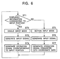
Referring to FIG. 6, in step 1 (ST1), a determination is
made as to whether the display 2 is in a state in which an
operation corresponding to the individual input portions of
the indicators 5 can be input. If the display 2 is
determined as being in that state (Yes) in step 1 (ST1), the
controller 11 changes the setting to a single input mode
(ST2). In the single input mode, it is possible to input
information by simply pressing or touching one of the
indicators 5 of the detection members 4. Next, the process
proceeds to step 3 (ST3), in which, when one of the
indicators 5 of the detection members 4 is pressed, an input
signal that corresponds to the input portion of the pressed
indicator 5. The process then proceeds to step 4 (ST4), in
which the input signal is converted by the controller 11
into an operation signal that has been assigned to the
individual detection member 4, so that information displayed
on the display 2 is changed to an image in accordance with
the operation signal.
-
On the other hand, in step 1 (ST1), when information
displayed on the display 2 does not correspond to an input
portion (No), the controller 11 changes the setting into the
motion input mode (ST5). In the motion input mode, an input
operation that does not correspond to the input portion of
the indicator 5 of each detection member 4 is possible.
Next, the process proceeds to step 6 (ST6), in which
continuously moving the finger from one detection member 4
to another detection member 4 causes the generation of an
input signal. The process then proceeds to step 7 (ST7), in
which the input signal is converted by the controller 11
into an operation signal as coordinate data. In that
process, the controller 11 also computes a moving direction
to generate the operation signal and information on the
display 2 is changed to an image in accordance with the
operation signal.
-
As described above, the processes at steps ST1 to ST4
or at steps ST1 and ST5 to ST7 are repeated.
-
The input device according to the present invention is
not limited to the specific embodiment described above. For
example, the display means may be provided on a housing
other than the housing on which the input device is provided.
Examples include a remote controller for a TV receiver. In
this case, the single input mode allows channel switching of
the TV receiver and the motion input mode allows menu
selection displayed on the screen thereof.
-
Alternatively, the input device according to the
present invention may be used for a remote controller for
equipment such as computers, audiovisual apparatuses, or
other household electric appliances, or may be used with an
operation panel directly incorporated in the body of such
equipment.
-
In addition, a dome-like inverting plate may be
provided on the reverse side of the input portion of each
detection member 4 of the input device 1, such that, when
the surface of the detection member 4 is pressed with a
finger, the dome-like inverting plate is inverted. With
this arrangement, a tactile feedback can be provided to the
finger, thereby providing an operation sensation to the
operator.