EP1333361A2 - Computing device having programmable state transitions - Google Patents
Computing device having programmable state transitions Download PDFInfo
- Publication number
- EP1333361A2 EP1333361A2 EP03250239A EP03250239A EP1333361A2 EP 1333361 A2 EP1333361 A2 EP 1333361A2 EP 03250239 A EP03250239 A EP 03250239A EP 03250239 A EP03250239 A EP 03250239A EP 1333361 A2 EP1333361 A2 EP 1333361A2
- Authority
- EP
- European Patent Office
- Prior art keywords
- time
- state
- computing device
- hibernate
- transition
- Prior art date
- Legal status (The legal status is an assumption and is not a legal conclusion. Google has not performed a legal analysis and makes no representation as to the accuracy of the status listed.)
- Withdrawn
Links
Images

Classifications
-
- G—PHYSICS
- G06—COMPUTING OR CALCULATING; COUNTING
- G06F—ELECTRIC DIGITAL DATA PROCESSING
- G06F1/00—Details not covered by groups G06F3/00 - G06F13/00 and G06F21/00
- G06F1/26—Power supply means, e.g. regulation thereof
- G06F1/32—Means for saving power
- G06F1/3203—Power management, i.e. event-based initiation of a power-saving mode
Definitions
- the invention pertains generally to computing devices and, more particularly, to computing devices that transition between operating states.
- Many computing devices such as portable laptop computers, handheld computers, and processor-based portable messaging devices, include a battery that allows the computing device to be temporarily operated at virtually any location, without regard to the availability of primary power from an external source. To extend the length of time that a user can operate the portable computing device away from the external source, many users carry extra batteries that can be installed when needed to continue operating the device.
- portable computing devices When portable computing devices are used in office environments, many users operate these devices according to predictable schedules. For example, a particular computing device user may come to work at a certain time every day, eat lunch at a certain time, and leave at a certain time. During lunch, and after the user leaves the office for the day, the user generally shuts off the computing device so that battery power can be conserved. This prolongs the life of the battery so that the portable computing device is available for use over a period that may include several days or longer.
- the device may remain operational for a lengthy period of time before being inactivated.
- the user may find that the computing device's battery has been depleted. This, in turn, requires that the user either replace the battery or return to a location where the device can be powered by an external source.
- a computing device having programmable state transitions allows a user to program the device with times of day at which the device enters particular operating states. This allows the device's power consumption to be programmably reduced at certain scheduled times while being increased at other times.
- the program control illustrated by the embodiments herein can allow the battery life of the computing device to be extended so that the device can be available for use over a longer period of time without recharging or replacing an associated battery, or requiring the user to find an external source with which to power the device.
- Figure 1 is a block diagram of a computing device that programmably transitions between states in accordance with a preferred embodiment of the invention.
- processor 100 runs an operating system and may run one or more application programs that allow the user of the computing device to interact with the computing device to perform various tasks. These tasks can include, but are not limited to, word processing, electronic mail, spreadsheet calculations, and so forth.
- the user preferably interacts with the computing device of Figure 1 using input device 160, which may include a keyboard, keypad, or other type of input device that controls the placement of characters or symbols on display 130.
- input device 160 may include a keyboard, keypad, or other type of input device that controls the placement of characters or symbols on display 130.
- graphical pointing device 170 which may include a mouse, trackpad, trackball, or other device used to position a cursor or other indicator on display 130 of the computing device.
- switch 180 enables the user to control at least some of the operating states in which the computing device of Figure 1 is capable of operating. For example, switch 180 may control the transition from a hibernate state to an active state.
- input device 160 and graphical pointing device 170 may also be used to control the operating state of the computing device of Figure 1.
- inputs from switch 180, graphical pointing device 170, and input device 160 are conveyed to keyboard controller 150.
- Keyboard controller 150 receives these inputs and requests processor 100 to transition to a particular operating state.
- Keyboard controller 150 also communicates with battery 190 by way of a logic unit (not shown) that monitors the health and status of the battery.
- Keyboard controller 150 responds to various unscheduled power management events that occur within the computing device represented by Figure 1.
- an unscheduled power management event is an event that affects the delivery of operating power to the computing device.
- An example of an unscheduled power management event can be a signal communicated from battery 190 indicating that the battery is no longer capable of supplying sufficient current to operate the computing device in its present operating state.
- Another example of an unscheduled power management event can be the user depressing switch 180 or interacting with either or both of graphical pointing device 170 and input device 160 in order to change an operating state of the computing device of Figure 1.
- a programmed time of day is input by the user of the computing device of Figure 1.
- the programmed time of day is stored within real-time clock memory 147, which is accessible to real-time clock 110.
- real-time clock 110 attains a time of day that is substantially equal to the programmed time of day, the real-time clock generates a signal that is received by processor 100.
- processor 100 reads current time event flag register 142 within memory 140.
- Processor 100 then transitions the computing device of Figure 1 to an operating state requested by the current time event flag stored within register 142.
- real-time clock 110 preferably makes use of a dedicated battery that provides power to the real-time clock.
- a user preferably interacts with the computing device of Figure 1 to input a set of programmed times of day as well as a time event flag that corresponds to each of the programmed times of day.
- Each programmed time of day and the corresponding time event flag are stored as an element of transition schedule 141 within memory 140.
- processor 100 in response to the signal generated by real-time clock 110 attaining a programmed time of day stored in real-time clock memory 147, processor 100 reads current time event flag register 142. After reading current time event flag register 142 and transitioning the computing device to the appropriate operating state, processor 100 reads the next element of transition schedule 141 within memory 140. The next (i.e. upcoming) programmed time of day is then stored into real-time clock memory 147 and the next current time event flag is stored in current time event flag register 142, thereby preparing the computing device for the next scheduled transition.
- processor 100 as well as other functional units of Figure 1, with the exception of real-time clock 110, are not operational.
- the computing device of Figure1 does not consume a substantial amount of power.
- processor 100 may perform various functions in which information relative to the user's activities is stored or saved within memory 140, or within other memory media accessible to processor 100 that are not shown in Figure 1. It is contemplated that the transition from the hibernate to the active state requires an amount of time sufficient to be a nuisance or to at least be noticeable to the user.
- processor 100 may retain some operational capability, but perhaps at a reduced level.
- Memory 140 may also be operational and available to processor 100 in the standby state, while various other devices coupled to processor 100 may not be operational. These other devices include display 130, input devices, as well as any hard disks or other memory media that consume power due to the motion of the media relative to a fixed reading or writing mechanism.
- real-time clock 110 continues to be operational. It is contemplated that the transition from the standby to the active state does not require the length of time needed to transition from the hibernate to the active state.
- the embodiments of the invention disclosed herein also contemplate an active state.
- the active state corresponds to a state in which a user may perform various interactions with the computing device of Figure 1.
- the computing device represented by Figure 1 may briefly enter the active state. This brief entry may be required so that processor 100 can perform logic related operations such as reading elements of transition schedule 141, storing information into memory 140 and real-time clock memory 147, and so forth.
- FIG. 2 is a graph of computing device power consumption versus time of day in accordance with a preferred embodiment of the invention.
- the hibernate, standby, and active states are shown on the vertical axis as corresponding to various power consumption levels.
- the computing device requires very little power.
- the standby state some power is consumed, such as that required to operate memory 140 of Figure 1.
- the active state a higher level of power is consumed, such as would be required to operate processor 100, display 130, input and pointing devices 160 and 170, memory 140, as well as any disk drives accessible to processor 100.
- the horizontal axis of Figure 2 shows a time of day.
- the computing device of Figure 1 transitions to certain operating states according to a programmed schedule that is repeated each day. Therefore, in the example of Figure 2, the computing device is programmed to transition from the hibernate state to the standby state at 6:00 AM. The computing device is maintained in the standby state from 6:00 AM until 8:00 AM. At 8:00 AM, the computing device transitions from a standby to an active state. At 12:00 PM, the computing device transitions from the active state to hibernate, and transitions back to the active state at 1:00 PM. From 1:00 PM until 6:00 PM, the computing device is maintained in the hibernate state. The device is maintained in the hibernate state from 6:00 PM until 6:00 AM the following day, when the process repeats.
- the times of day at which the various state transitions occur are under the control of the user of the computing device.
- the user may wish to transition from hibernate to standby at an earlier or later time than the 6:00 AM transition time shown in Figure 2.
- the user may not wish for the computing device to programmably enter the active state at any time of day.
- the flexibility to adjust the times of day at which the various state transitions occur, as well as the states which are transitioned to, are contemplated as being under the control of the user of the computing device.
- the user may choose numerous transitions between these states throughout the day, week, or other period.
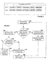
- Figure 3 is a panel presented to the user in association with a program that allows the user to input a state transition time schedule into a computing device in accordance with a preferred embodiment of the invention.
- Figure 3 includes fields that allow the user to program the computing device with a desired state transition schedule.
- the computing device has been programmed to transition to the standby state at 6:00 AM, to transition to the active state at 8:00 AM, to transition into and out of the hibernate state at 12:00 PM and 1:00 PM (respectively), and to transition to the hibernate state at 6:00 PM.
- the "Standby”, "Active”, and “Hibernate” fields of Figure 3 are selectable.
- the user may select "Standby” in lieu of the "Hibernate” selection.
- the computing device would transition from the standby to the active state at 8:00 AM and return to the standby state at 6:00 PM.
- additional columns are added to the panel of Figure 3.
- additional columns may be added to accommodate these additional transitions.
- additional rows may be added to include transitions that are desired during weekends and holidays.
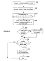
- Figure 4 is a flowchart for a method used to program a computing device to perform time event driven state transitions in accordance with a preferred embodiment of the invention.
- the computing device of Figure 1 operating in conjunction with an operating system that runs on processor 100, is suitable for performing the method.
- time event includes events programmably scheduled by the user.
- the computing device can be initialized so that time event flags, such as those described in reference to Figure 7, can be responded to.
- the method of Figure 4 begins at block 300 in which a transition schedule panel, such as that shown in Figure 3, is presented to a user.
- the method continues at block 302 in which time event flags, such as the Active, Standby, and Hibernate flags are received.
- the method continues at block 304 in which the computing device receives the times of day corresponding to the time event flags received in block 302.
- each time of day (as programmed by the user) as well as a time event flag corresponding to each programmed time of day are stored as elements of a transition schedule within a memory of the computing device.
- Block 306 can also include removing the transition schedule panel presented to the user in block 300.
- the method continues at block 308, in which a determination is made as to whether a time event is currently pending. If a time event is currently pending, block 310 is executed in which the time event is canceled and the method continues at block 312. If a time event is not currently pending, the method continues at block 312 without canceling the current time event flag.
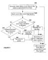
- Figure 5 is flowchart for a method used by a computing device for transitioning between states in accordance with a preferred embodiment of the invention.
- the computing device of Figure 1 operating in conjunction with an operating system that runs on processor 100, is suitable for performing the method.
- the state transitions of Figure 2 are used for the example of Figure 5.
- the method of Figure 5 begins at block 320, in which a real-time clock generates a signal when the current time of day attains a programmed time of day.
- the method continues at block 325, in which a processor reads a current time event flag register in response to receiving the signal.
- the method continues at block 330, in which the current time event flag is examined to determine if the flag corresponds to a transition to a standby state. If the received time of day event flag does correspond to a request to transition to standby, block 340 is executed in which the computing device begins the transition to standby.
- the method continues at block 355 in which the next (or upcoming) time of day is stored in a memory location accessible to the real-time clock.
- the method continues with storing the current time event flag that corresponds to time of day stored in block 355.
- Control then returns to block 320, wherein a signal is generated when the current time of day attains the programmed time of day stored within the memory accessible to the real-time clock.
- the method of Figure 5 can then be repeated throughout the day according to a programmed schedule such as that programmed by way of the transition schedule panel of Figure 3, for example.
- block 335 is executed in which the current time event flag is evaluated to determine if the flag is request to transition to an active state. If the decision of block 335 indicates a request to transition to an active state, block 350 is executed in which the computing device is transitioned to an active state.
- the method continues at block 355 in which in which the next (or upcoming) time of day is stored in a memory location accessible to the real-time clock.
- the method continues at block 358 with storing the current time event flag that corresponds to time of day stored in block 355. Control then returns to block 320, wherein a signal is generated when the current time of day attains the programmed time of day stored within the memory accessible to the real-time clock.
- block 345 is executed in which the processor transitions the computing device to the hibernate state.
- the method continues at block 355 in which in which the next time of day is stored in a memory location accessible to the real-time clock.
- the method continues at block 358 with storing the current time event flag that corresponds to time of day stored in block 355. Control then returns to block 320.
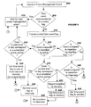
- Figure 6 is a flowchart for a method of responding to a power management event in a computing device having programmable state transitions in accordance with a preferred embodiment of the invention.
- the method of Figure 6 handles various programmed power management events, such as the scheduled time events described herein. Additionally, the method of Figure 6 handles unscheduled (or unprogrammed) power management events.
- an unscheduled power management event is an event that affects the delivery of operating power to the computing device.
- An example of an unscheduled power management event can be a signal communicated from a battery that indicates the battery is no longer capable of supplying sufficient current to operate the computing device in its present operating state.
- Another example of an unscheduled power management event can be the user depressing an "on" switch that places the computing device in the active state, or interacting with an input device used to initiate a state transition.
- a further example of an unscheduled power management event can be a timer-requested state transition, such as a timeout that automatically transitions the computing device after the user has left the device unattended.
- the method of Figure 6 begins at block 500 in which a power management event is received.
- the method continues at block 505 in which a determination is made as to whether the received power management event has been requested by a time event flag. If the received power management event is the result of receiving a time event flag, the method continues at block 550, in which the computing device waits for the next power management event flag.
- the method continues at block 510 in which the current time event flag, such as the flag stored in the current time event register, is canceled.
- This cancellation prevents the computing device from programmably transitioning to an active state when a battery, for example, can no longer provide the required current to operate the computing device in the active state.
- the method continues at block of 520 in which a determination is made as to whether the unscheduled power management event is a request to transition to an active state from a standby or hibernate state. If the decision of block of 520 indicates that the unscheduled power management event is a request to transition to an active state, block 540 is executed in which a decision is made as to whether the current time of day corresponds to a scheduled active period, such as the 1:00 PM to 6:00 PM period of Figure 2. In the event that the current time of day corresponds to a scheduled active time period, block 560 is executed in which the current time event flag is set to either hibernate or standby, depending on the desired programmed state transitions.
- a scheduled active period such as the 1:00 PM to 6:00 PM period of Figure 2.
- the computing device If the current time event flag is programmed to enter the hibernate state, the computing device is placed into the hibernate state the next time the real-time clock attains a programmed time (e.g. 6:00 PM). If the current time event flag is programmed to enter the standby state, the computing device can be placed into a standby state at the next programmed time.
- a programmed time e.g. 6:00 PM
- the method continues at block 550 in which the computing device waits for the next power management event before returning to block 500 and without setting the current time event flag to hibernate. This can be useful in the event that the user is operating the computing device in the evening (e.g. after 6:00 PM) and does not wish the computing device to transition to hibernate upon the next programmed time event (e.g. 6:00 AM).
- block 530 is executed in which a determination is made as to whether the unscheduled power management event is a request to transition to a standby state. If a standby state has been requested, block 570 is executed in which a decision is made as to whether the current time of day corresponds to a scheduled active time period (e.g. 8:00 AM to 12:00 PM). If the current time of day does correspond to a scheduled active time period, block 590 is executed in which the current time event flag is set to hibernate.
- a scheduled active time period e.g. 8:00 AM to 12:00 PM
- the computing device By setting the current time event flag to hibernate, the computing device is prepared to enter the hibernate state at the next programmed transition time. This can be useful when the user sets the computing device to the standby state in the afternoon (for example) wherein the next programmed transition time should place the computing device in hibernate, at 6:00 PM. The method then continues at block 550 in which the computing device waits for the next power management event.
- block 600 is executed in which the transition to standby is rejected.
- Block 610 is then executed in which the current time event flag is set to standby, and block 620 is executed in which the computing device is requested to transition to hibernate.
- This can be useful when the user sets the computing device to a standby state during a time period that corresponds to the computing device's hibernate period (e.g. 6:00 PM to 6:00 AM). In this case, setting the current time event flag to standby and transitioning the device to hibernate allows the device to transition to standby at the next programmed time (such as 6:00 AM). Control then returns to block 550.
- block 580 is executed in which a decision is made as to whether the unscheduled power management event is a request to transition to a hibernate state. If the decision of block 580 indicates that the unscheduled power management event is not a request to transition to a hibernate state, the method returns to block 550 in which the device waits for the next power management event. This can be useful in response to a battery-related event, such as a drop in voltage output, in which it may be advantageous for the computing device to wait for the next power management event, such as the user requesting an active state after the battery has been charged.
- a battery-related event such as a drop in voltage output
- block 630 is executed in which the time event flag is set to standby. Control then returns to block 550.
- This can be useful when the user has requested the computing device to enter the hibernate state after using the device during the scheduled hibernate period (e.g. 6:00 PM to 6:00 AM). In this case, the computing device is prepared to enter the standby state at 6:00 AM.
- FIG. 6 various blocks have been included in the method in order to illustrate details that may be useful in some applications.
- another method of responding to a power management event in a computing device having programmable state transitions may only require the cancellation of a current time event flag (block 510), an unscheduled power management event determination block (such as block 520), a current time of day determination block (such as block 540), as well as storing one of a standby and a hibernate current time event flag in memory (block 560) if the unscheduled power management event is a request to transition to an active state and if the current time of day corresponds to a scheduled active time period.
- Figure 7 is a flowchart for a method of responding to a time event used in a computing device having programmable state transitions in accordance with a preferred embodiment of the invention.
- the method of Figure 7 begins at block 700 in which a time event signal is received by a processor.
- the method continues at block 710 in which a current time event flag register is read in order to determine the event that corresponds to the received time event signal. If the current time event flag indicates a request to set the computing device to a hibernate state, block 720 is executed in which the current time event flag is set to standby.
- the computing device is prepared for the next transition, which, for the state transitions of Figure 2, would be the transition to the standby state (6:00 AM).
- the method continues at block 730 in which a decision is made as to whether the computing device is being requested to transition from the standby state to the hibernate state. If the computer is being transitioned from the standby to the hibernate state, block 770 is performed in which the computing device is transitioned to hibernate. The method continues at block 780 in which the processor waits for the next time event. If the decision of block 730 indicates that the computing device is not being transitioned from standby to hibernate, indicating that the computing device is in an active state, block 760 is executed in which a confirmation panel is presented. The confirmation panel allows a user, who might be interacting with the device, to stop the programmed transition to the hibernate state. If the user confirms the transition, or after a specified time period, the method continues at block 770 in which the transition to hibernate is requested. Block 780 is then executed in which the processor waits for the next time event.
- block 740 is executed in which the time event flag is set to hibernate.
- the method continues by executing block 750 in which a transition to hibernate is requested.
- Block 780 is then executed in which the processor waits for the next time event. Control returns to block 700, thus preparing the processor to receive the next time event flag.
- FIG 7 various blocks have been included in the method in order to illustrate details that may be useful in some applications.
- another method of a responding to a time event used in a computing device having programmable state transitions may only require determining if the time event flag is a request to set the computing device to a hibernate state (such as in block 710), setting a time event flag to standby if the time event flag is set to hibernate (such as in block 720), and requesting the computing device to enter the hibernate state (such as in block 770).
Landscapes
- Engineering & Computer Science (AREA)
- Theoretical Computer Science (AREA)
- Physics & Mathematics (AREA)
- General Engineering & Computer Science (AREA)
- General Physics & Mathematics (AREA)
- Power Sources (AREA)
- Calculators And Similar Devices (AREA)
- Programmable Controllers (AREA)
Abstract
Description
An example of an unscheduled power management event can be a signal communicated from a battery that indicates the battery is no longer capable of supplying sufficient current to operate the computing device in its present operating state. Another example of an unscheduled power management event can be the user depressing an "on" switch that places the computing device in the active state, or interacting with an input device used to initiate a state transition. A further example of an unscheduled power management event can be a timer-requested state transition, such as a timeout that automatically transitions the computing device after the user has left the device unattended.
Claims (10)
- A computing device having programmable state transitions, comprising:a real-time clock (110) that generates a signal in response to said real-time clock (110) attaining a programmed time of day; anda processor (100), coupled to said real-time clock (110) that receives said signal and transitions from a hibernate to a standby state.
- The computing device of claim 1, wherein said real-time clock (110) generates a second signal in response to attaining a second programmed time of day, and wherein said processor receives said second signal and transitions from said standby to an active state.
- In a computing device, a method for transitioning from a hibernate to a standby state, said method comprising:a real-time clock generating (320) a signal that is conveyed to a processor coupled to said real-time clock, said signal indicating that said real-time clock has attained a programmed time of day; andsaid processor transitioning (340) from a hibernate to a standby state in response to receiving said signal.
- The method of claim 3, further comprising said processor reading a memory location (325) that stores a time event flag, said time event flag requesting said processor to transition from said hibernate to said standby state.
- The method of claim 4, further comprising said processor storing (358) a second time event flag that requests said processor to transition from said standby to said hibernate state, said storing being performed after said reading.
- In a computing device having programmable state transitions, a method for responding to a power management event, comprising:canceling (510) a time event flag stored in a memory location;determining (520, 530, 580) said power management event;storing a second time event flag into said memory location, wherein said second time event flag is set to one of a standby and a hibernate state, said storing occurring if said power management event is a request to transition to an active state and if a current time of day corresponds to a scheduled active time period.
- The method of claim 6 wherein said second time event flag is a request to transition to said hibernate state.
- The method of claim 6, wherein said second time event flag is a request to transition to said standby state.
- The method of claim 6, wherein if said power management event is a request to transition to said standby state and if said current time of day does not correspond to a scheduled active period, then additionally performing:rejecting said request to transition said computing device to said standby state;setting said second time event flag to standby; andsetting said time event flag to hibernate.
- The method of claim 6, wherein if said power management event is a request to transition to a hibernate state, then additionally performing:setting said time event flag to hibernate.
Applications Claiming Priority (2)
| Application Number | Priority Date | Filing Date | Title |
|---|---|---|---|
| US66378 | 2002-01-30 | ||
| US10/066,378 US6961859B2 (en) | 2002-01-30 | 2002-01-30 | Computing device having programmable state transitions |
Publications (2)
| Publication Number | Publication Date |
|---|---|
| EP1333361A2 true EP1333361A2 (en) | 2003-08-06 |
| EP1333361A3 EP1333361A3 (en) | 2004-04-14 |
Family
ID=22069119
Family Applications (1)
| Application Number | Title | Priority Date | Filing Date |
|---|---|---|---|
| EP03250239A Withdrawn EP1333361A3 (en) | 2002-01-30 | 2003-01-15 | Computing device having programmable state transitions |
Country Status (3)
| Country | Link |
|---|---|
| US (1) | US6961859B2 (en) |
| EP (1) | EP1333361A3 (en) |
| JP (1) | JP3973569B2 (en) |
Families Citing this family (45)
| Publication number | Priority date | Publication date | Assignee | Title |
|---|---|---|---|---|
| TWI235298B (en) * | 2002-11-13 | 2005-07-01 | Mitac Technology Corp | Method to read the battery status by the operating system of portable computer |
| US7100062B2 (en) * | 2003-01-28 | 2006-08-29 | Hewlett-Packard Development Company, L.P. | Power management controller and method |
| US8166422B2 (en) * | 2003-11-21 | 2012-04-24 | Kyocera Corporation | System and method for arranging and playing a media presentation |
| KR100644608B1 (en) * | 2004-01-09 | 2006-11-10 | 삼성전자주식회사 | Apparatus and method for controlling power saving mode of electrical / electronic devices |
| US7203854B2 (en) * | 2004-02-12 | 2007-04-10 | Microsoft Corporation | System for reconfiguring a computer between a high power and high functionality configuration and a low power and low functionality configuration |
| KR100677342B1 (en) * | 2004-07-30 | 2007-02-02 | 엘지전자 주식회사 | Method for setting configuration of mobile terminal |
| US20060095805A1 (en) * | 2004-10-29 | 2006-05-04 | Broyles Paul J | Suppression of sleep mode in a computing device via date/time windows |
| US20060284840A1 (en) * | 2005-06-15 | 2006-12-21 | Research In Motion Limited | Portable electronic device including pointer and related methods |
| DE602005016908D1 (en) | 2005-06-15 | 2009-11-12 | Research In Motion Ltd | Power control for portable electronic device with an indication device |
| JP4694333B2 (en) * | 2005-09-30 | 2011-06-08 | 株式会社日立製作所 | Computer system, storage device, system management device, and disk device power control method |
| EP1777608B1 (en) | 2005-10-07 | 2010-01-20 | Research In Motion Limited | Portable electronic device including trackball unit and associated methods |
| US20070080946A1 (en) * | 2005-10-07 | 2007-04-12 | Research In Motion Limited | Portable electronic device including trackball unit and associated methods |
| US7797555B2 (en) * | 2006-05-12 | 2010-09-14 | Intel Corporation | Method and apparatus for managing power from a sequestered partition of a processing system |
| JP4984689B2 (en) * | 2006-07-04 | 2012-07-25 | 日本電気株式会社 | Disk array control device, method, and program |
| US8301195B2 (en) * | 2006-07-05 | 2012-10-30 | Agere Systems Inc. | Systems and methods for mobile data storage and acquisition |
| US7689850B2 (en) * | 2006-11-28 | 2010-03-30 | Dell Products L.P. | System and method for adaptive information handling system power management |
| JP4595937B2 (en) * | 2006-12-28 | 2010-12-08 | ソニー株式会社 | Information processing apparatus, information processing method, and program |
| US8510581B2 (en) * | 2007-03-26 | 2013-08-13 | Freescale Semiconductor, Inc. | Anticipation of power on of a mobile device |
| US20080294798A1 (en) * | 2007-05-23 | 2008-11-27 | Lynch Thomas W | Portable electronic device management |
| EP2063327A1 (en) * | 2007-11-26 | 2009-05-27 | EM Microelectronic-Marin SA | Electronic circuit for managing the operation of peripheral devices of a watch |
| US8281166B2 (en) * | 2008-03-10 | 2012-10-02 | Virdiem Corporation | System and method for computer power control |
| US9520743B2 (en) | 2008-03-27 | 2016-12-13 | Echostar Technologies L.L.C. | Reduction of power consumption in remote control electronics |
| US8082455B2 (en) * | 2008-03-27 | 2011-12-20 | Echostar Technologies L.L.C. | Systems and methods for controlling the power state of remote control electronics |
| US7992022B2 (en) * | 2008-04-17 | 2011-08-02 | International Business Machines Corporation | Method and apparatus for setting computer-working-hours-based shutdown options |
| US7907060B2 (en) * | 2008-05-08 | 2011-03-15 | Echostar Technologies L.L.C. | Systems, methods and apparatus for detecting replacement of a battery in a remote control |
| US8305249B2 (en) | 2008-07-18 | 2012-11-06 | EchoStar Technologies, L.L.C. | Systems and methods for controlling power consumption in electronic devices |
| EP2316058B1 (en) * | 2008-08-12 | 2023-12-20 | Littelfuse, Inc. | System and method for conserving power applied to an electrical apparatus |
| US8095815B2 (en) * | 2008-10-14 | 2012-01-10 | Hewlett-Packard Development Company, L.P. | System for reducing power consumption in an electronic chip |
| TW201030619A (en) * | 2009-02-12 | 2010-08-16 | Asustek Comp Inc | Method of automatic start-up of a computer system |
| WO2012022996A1 (en) * | 2010-08-18 | 2012-02-23 | Thomson Licensing | Methods for operating an apparatus having multiple stand-by modes |
| US9134784B2 (en) * | 2011-05-31 | 2015-09-15 | Lenovo (Singapore) Pte. Ltd. | Predictive power state transitions for information handling devices |
| US9069551B2 (en) * | 2011-12-22 | 2015-06-30 | Sandisk Technologies Inc. | Systems and methods of exiting hibernation in response to a triggering event |
| US9389673B2 (en) | 2011-12-22 | 2016-07-12 | Sandisk Technologies Inc. | Systems and methods of performing a data save operation |
| US9092150B2 (en) | 2011-12-22 | 2015-07-28 | Sandisk Technologies Inc. | Systems and methods of performing a data save operation |
| US8914594B2 (en) | 2011-12-22 | 2014-12-16 | Sandisk Technologies Inc. | Systems and methods of loading data from a non-volatile memory to a volatile memory |
| JP5995571B2 (en) * | 2012-07-17 | 2016-09-21 | キヤノン株式会社 | Information processing apparatus and control method thereof |
| EP3011408B1 (en) * | 2013-06-20 | 2019-08-07 | Hewlett-Packard Development Company, L.P. | Computing device power states |
| DE102013106699B3 (en) * | 2013-06-26 | 2014-02-27 | Fujitsu Technology Solutions Intellectual Property Gmbh | Computer system i.e. desktop computer system for e.g. chat application, has interfaces calling function for operation of computer system in absence mode to enable power-saving state for computer system, if absence of user is detected |
| US9459683B2 (en) * | 2013-09-27 | 2016-10-04 | Intel Corporation | Techniques for entering a low power state |
| US20150169033A1 (en) * | 2013-12-13 | 2015-06-18 | Cisco Technology, Inc. | Systems and methods for power management in stackable switch |
| US9445038B2 (en) * | 2014-01-30 | 2016-09-13 | Vizio Inc | Predictive time to turn on a television based on previously used program schedules |
| US20170262208A1 (en) * | 2016-03-08 | 2017-09-14 | Kabushiki Kaisha Toshiba | Memory device, host device, and information processing device |
| US10198059B2 (en) | 2016-04-20 | 2019-02-05 | Microsoft Technology Licensing, Llc | Adaptive doze to hibernate |
| JP6905189B2 (en) * | 2017-08-18 | 2021-07-21 | 富士通株式会社 | Information processing equipment, information processing system and control program |
| US20260067537A1 (en) * | 2024-09-04 | 2026-03-05 | Atmosphere.tv | Zero touch play |
Family Cites Families (14)
| Publication number | Priority date | Publication date | Assignee | Title |
|---|---|---|---|---|
| US5396635A (en) * | 1990-06-01 | 1995-03-07 | Vadem Corporation | Power conservation apparatus having multiple power reduction levels dependent upon the activity of the computer system |
| US5542035A (en) * | 1993-10-27 | 1996-07-30 | Elonex Technologies | Timer-controlled computer system shutdown and startup |
| US5590342A (en) * | 1994-11-29 | 1996-12-31 | Intel Corporation | Method and apparatus for reducing power consumption in a computer system using virtual device drivers |
| WO1996027827A1 (en) * | 1995-03-06 | 1996-09-12 | Intel Corporation | A computer system with unattended on-demand availability |
| US5902352A (en) * | 1995-03-06 | 1999-05-11 | Intel Corporation | Method and apparatus for task scheduling across multiple execution sessions |
| US5974552A (en) * | 1995-12-29 | 1999-10-26 | Samsung Electronics Co., Ltd. | Method and apparatus for executing a scheduled operation after wake up from power off state |
| JP2988866B2 (en) * | 1996-02-29 | 1999-12-13 | 株式会社東芝 | Computer system |
| EP0894301A1 (en) * | 1996-03-14 | 1999-02-03 | Rockwell Semiconductor Systems, Inc. | Method and apparatus for power management using power control |
| KR100243129B1 (en) * | 1997-08-27 | 2000-02-01 | 윤종용 | Method of controlling power on/off and printer applied thereof |
| US6070215A (en) * | 1998-03-13 | 2000-05-30 | Compaq Computer Corporation | Computer system with improved transition to low power operation |
| US6189106B1 (en) * | 1998-05-08 | 2001-02-13 | Gateway, Inc. | Method and apparatus for operating an electronic device at an optimal power mode based upon a scheduled event |
| JP3712556B2 (en) * | 1999-02-26 | 2005-11-02 | 富士通株式会社 | Power supply device, power supply control device, and schedule operation monitoring control method for power supply system |
| US6539485B1 (en) * | 1999-05-24 | 2003-03-25 | Jonathan Liu | Intelligent sleep mode indicator |
| US6654895B1 (en) * | 1999-11-08 | 2003-11-25 | Intel Corporation | Adaptive power management in a computing system |
-
2002
- 2002-01-30 US US10/066,378 patent/US6961859B2/en not_active Expired - Lifetime
-
2003
- 2003-01-15 EP EP03250239A patent/EP1333361A3/en not_active Withdrawn
- 2003-01-21 JP JP2003012858A patent/JP3973569B2/en not_active Expired - Fee Related
Also Published As
| Publication number | Publication date |
|---|---|
| US20030145242A1 (en) | 2003-07-31 |
| US6961859B2 (en) | 2005-11-01 |
| JP2003263247A (en) | 2003-09-19 |
| EP1333361A3 (en) | 2004-04-14 |
| JP3973569B2 (en) | 2007-09-12 |
Similar Documents
| Publication | Publication Date | Title |
|---|---|---|
| US6961859B2 (en) | Computing device having programmable state transitions | |
| US8190939B2 (en) | Reducing power consumption of computing devices by forecasting computing performance needs | |
| US5345392A (en) | Battery charge monitor for a personal computer | |
| Helmbold et al. | A dynamic disk spin-down technique for mobile computing | |
| US8112642B2 (en) | Method and system for controlling power in a chip through a power-performance monitor and control unit | |
| US6775784B1 (en) | Power supply control circuit and method for cutting off unnecessary power to system memory in the power-off state | |
| CN101067758B (en) | An energy management method for embedded systems | |
| CA2145162C (en) | Method and system of power management for a data processing system | |
| Benini et al. | Monitoring system activity for OS-directed dynamic power management | |
| US6986068B2 (en) | Arithmetic processing system and arithmetic processing control method, task management system and task management method | |
| CN103502946B (en) | Method and system for dynamically controlling power to multiple cores in a multi-core processor of a portable computing device | |
| Dhiman et al. | System-level power management using online learning | |
| EP1510908B1 (en) | Processor resource power management | |
| KR100661851B1 (en) | Power management method for platform and that platform | |
| JP2003015783A (en) | Information processing apparatus and power management method thereof | |
| JPH11289677A (en) | System for estimating remaining usable time of battery | |
| WO1997034218A1 (en) | Method and apparatus for power management using power control | |
| Cho et al. | A high performance load balance strategy for real‐time multicore systems | |
| WO2011114427A1 (en) | Device setting program, method, and information processing device | |
| KR101082347B1 (en) | Power saving management system according to user pattern | |
| JPH10143274A (en) | CPU clock control device | |
| JP5683885B2 (en) | Information processing device | |
| Lin et al. | Applying pinwheel scheduling and compiler profiling for power-aware real-time scheduling | |
| Dinh-Duc | An efficient scheduling for low power in real-time embedded systems | |
| Chu et al. | CPPM: a comprehensive power-aware processor manager for a multicore system |
Legal Events
| Date | Code | Title | Description |
|---|---|---|---|
| PUAI | Public reference made under article 153(3) epc to a published international application that has entered the european phase |
Free format text: ORIGINAL CODE: 0009012 |
|
| AK | Designated contracting states |
Designated state(s): AT BE BG CH CY CZ DE DK EE ES FI FR GB GR HU IE IT LI LU MC NL PT SE SI SK TR |
|
| AX | Request for extension of the european patent |
Extension state: AL LT LV MK RO |
|
| PUAL | Search report despatched |
Free format text: ORIGINAL CODE: 0009013 |
|
| AK | Designated contracting states |
Kind code of ref document: A3 Designated state(s): AT BE BG CH CY CZ DE DK EE ES FI FR GB GR HU IE IT LI LU MC NL PT SE SI SK TR |
|
| AX | Request for extension of the european patent |
Extension state: AL LT LV MK RO |
|
| 17P | Request for examination filed |
Effective date: 20040924 |
|
| AKX | Designation fees paid |
Designated state(s): DE FR GB |
|
| RAP1 | Party data changed (applicant data changed or rights of an application transferred) |
Owner name: HEWLETT-PACKARD DEVELOPMENT COMPANY, L.P. |
|
| 17Q | First examination report despatched |
Effective date: 20140626 |
|
| STAA | Information on the status of an ep patent application or granted ep patent |
Free format text: STATUS: THE APPLICATION IS DEEMED TO BE WITHDRAWN |
|
| 18D | Application deemed to be withdrawn |
Effective date: 20170801 |