EP1333206A1 - Check valve having adjustable lift, packing assembly, and retrofit kit for same - Google Patents
Check valve having adjustable lift, packing assembly, and retrofit kit for same Download PDFInfo
- Publication number
- EP1333206A1 EP1333206A1 EP20020258420 EP02258420A EP1333206A1 EP 1333206 A1 EP1333206 A1 EP 1333206A1 EP 20020258420 EP20020258420 EP 20020258420 EP 02258420 A EP02258420 A EP 02258420A EP 1333206 A1 EP1333206 A1 EP 1333206A1
- Authority
- EP
- European Patent Office
- Prior art keywords
- washers
- ball stop
- stop member
- ball
- washer
- Prior art date
- Legal status (The legal status is an assumption and is not a legal conclusion. Google has not performed a legal analysis and makes no representation as to the accuracy of the status listed.)
- Withdrawn
Links
- 238000012856 packing Methods 0.000 title claims abstract description 13
- 239000012530 fluid Substances 0.000 description 9
- 238000005553 drilling Methods 0.000 description 2
- 238000004519 manufacturing process Methods 0.000 description 2
- 230000003247 decreasing effect Effects 0.000 description 1
- 230000000694 effects Effects 0.000 description 1
- 239000000463 material Substances 0.000 description 1
- 238000005086 pumping Methods 0.000 description 1
- 238000007789 sealing Methods 0.000 description 1
Images


Classifications
-
- F—MECHANICAL ENGINEERING; LIGHTING; HEATING; WEAPONS; BLASTING
- F16—ENGINEERING ELEMENTS AND UNITS; GENERAL MEASURES FOR PRODUCING AND MAINTAINING EFFECTIVE FUNCTIONING OF MACHINES OR INSTALLATIONS; THERMAL INSULATION IN GENERAL
- F16K—VALVES; TAPS; COCKS; ACTUATING-FLOATS; DEVICES FOR VENTING OR AERATING
- F16K15/00—Check valves
- F16K15/02—Check valves with guided rigid valve members
- F16K15/04—Check valves with guided rigid valve members shaped as balls
-
- F—MECHANICAL ENGINEERING; LIGHTING; HEATING; WEAPONS; BLASTING
- F04—POSITIVE - DISPLACEMENT MACHINES FOR LIQUIDS; PUMPS FOR LIQUIDS OR ELASTIC FLUIDS
- F04B—POSITIVE-DISPLACEMENT MACHINES FOR LIQUIDS; PUMPS
- F04B53/00—Component parts, details or accessories not provided for in, or of interest apart from, groups F04B1/00 - F04B23/00 or F04B39/00 - F04B47/00
- F04B53/10—Valves; Arrangement of valves
- F04B53/1002—Ball valves
- F04B53/101—Ball valves having means for limiting the opening height
-
- Y—GENERAL TAGGING OF NEW TECHNOLOGICAL DEVELOPMENTS; GENERAL TAGGING OF CROSS-SECTIONAL TECHNOLOGIES SPANNING OVER SEVERAL SECTIONS OF THE IPC; TECHNICAL SUBJECTS COVERED BY FORMER USPC CROSS-REFERENCE ART COLLECTIONS [XRACs] AND DIGESTS
- Y10—TECHNICAL SUBJECTS COVERED BY FORMER USPC
- Y10T—TECHNICAL SUBJECTS COVERED BY FORMER US CLASSIFICATION
- Y10T137/00—Fluid handling
- Y10T137/7722—Line condition change responsive valves
- Y10T137/7837—Direct response valves [i.e., check valve type]
- Y10T137/7904—Reciprocating valves
-
- Y—GENERAL TAGGING OF NEW TECHNOLOGICAL DEVELOPMENTS; GENERAL TAGGING OF CROSS-SECTIONAL TECHNOLOGIES SPANNING OVER SEVERAL SECTIONS OF THE IPC; TECHNICAL SUBJECTS COVERED BY FORMER USPC CROSS-REFERENCE ART COLLECTIONS [XRACs] AND DIGESTS
- Y10—TECHNICAL SUBJECTS COVERED BY FORMER USPC
- Y10T—TECHNICAL SUBJECTS COVERED BY FORMER US CLASSIFICATION
- Y10T137/00—Fluid handling
- Y10T137/7722—Line condition change responsive valves
- Y10T137/7837—Direct response valves [i.e., check valve type]
- Y10T137/7904—Reciprocating valves
- Y10T137/7908—Weight biased
- Y10T137/7909—Valve body is the weight
-
- Y—GENERAL TAGGING OF NEW TECHNOLOGICAL DEVELOPMENTS; GENERAL TAGGING OF CROSS-SECTIONAL TECHNOLOGIES SPANNING OVER SEVERAL SECTIONS OF THE IPC; TECHNICAL SUBJECTS COVERED BY FORMER USPC CROSS-REFERENCE ART COLLECTIONS [XRACs] AND DIGESTS
- Y10—TECHNICAL SUBJECTS COVERED BY FORMER USPC
- Y10T—TECHNICAL SUBJECTS COVERED BY FORMER US CLASSIFICATION
- Y10T137/00—Fluid handling
- Y10T137/7722—Line condition change responsive valves
- Y10T137/7837—Direct response valves [i.e., check valve type]
- Y10T137/7904—Reciprocating valves
- Y10T137/7908—Weight biased
- Y10T137/7909—Valve body is the weight
- Y10T137/791—Ball valves
Definitions
- This invention relates generally to fluid valves and more particularly to fluid valves having adjustable lifts for pumps.
- check valves are typically used to limit the direction of flow through a pump.
- these valves include a ball closure element which, responsive to the direction of fluid movement through the valve, closes to prevent the passage of the fluid in one direction by moving into engagement with a valve seat and opens to permit the passage of the fluid in an opposite direction by moving away from the valve seat.
- a ball stop element is generally used to limit the distance, commonly referred to as "lift,” to which the ball closure element is permitted to move away from the valve seat.
- FIG. 1 An exemplary pump having check valves with ball stops that limit the lift of a ball closure element is shown in US-A-5,647,737.
- a two-ball style pump available from Ingersoll-Rand Company, Woodcliff Lake, NJ as the ARO Model 66475 pump incorporates such check valves having a ball closure element located within a cylindrical ball guide in its lower pump end to control the inlet flow of a fluid to be pumped into the pump.
- a pin positioned in holes located in a ball guide is used as a ball stop element to increase or decrease the lift of the ball valve element in the valve body. If more ball lift is desired for heavier (i.e., more viscous) fluids, the pin is moved to holes in the ball guide that are further away from the valve seat. Conversely, if less ball lift is desired for lighter (i.e., less viscous) materials, the pin is moved to holes located closer to the valve seat in the ball guide.
- a packing assembly for a check valve characterised by a ball stop member having opposed first and second contact portions, and at least two washers being provided in a stacking configuration selected from one in which all of the at least two washers are stacked against the first contact portion of the ball stop member, one in which all of the at least two washers are stacked against the second contact portion of the ball stop member, and one in which at least one of the at least two washers is stacked against the first contact portion of the ball stop member and at least one of the at least two washers is stacked against the second contact portion of the ball stop member.
- a check valve assembly for a pump comprising a check ball, a ball stop member having opposed first and second contact portions, and at least two washers being provided in a stacking configuration selected from one in which all of the at least two washers are stacked against the first contact portion of the ball stop member, one in which all of the at least two washers are stacked against the second contact portion of the ball stop member, and one in which at least one of the at least two washers is stacked against the first contact portion of the ball stop member and at least one of the at least two washers is stacked against the second contact portion of the ball stop member.
- a packing assembly retrofit kit for a for a check valve comprising a ball stop member having opposed first and second contact portions, and at least two washers being provided in a stacking configuration selected from one in which all of the at least two washers are stacked against the first contact portion of the ball stop member, one in which all of the at least two washers are stacked against the second contact portion of the ball stop member, and one in which at least one of the at least two washers is stacked against the first contact portion of the ball stop member and at least one of the at least two washers is stacked against the second contact portion of the ball stop member.
- Foot valve 70 is attached to an elongate pump tube 62 of a reciprocating pump (not shown) well known to one skilled in the relevant art.
- Foot valve 70 includes a check valve having a check ball 74. seated in check valve seat 76 which is held by a foot valve body 75 into which fluid to be pumped enters at the bottom. Attached to foot valve body 75 is a ball guide 79 in which check ball 74 moves into and out of sealing engagement with check valve seat 76.
- Foot valve body 70 is threadingly attached to pump tube 62 by a threaded sleeve 69. As shown in Fig. 1, a ball stop pin 80 is passed through circular openings 81 formed in ball guide 79.
- Fig. 2 As shown in greater detail in Fig. 2 in which the ball stop pin 80 has been removed, multiple pairs of cylindrical openings 81 are provided for positioning the ball stop pin 80.
- the length of travel of the check valve ball 74 shown by the phantom ball positions in Fig. 2 can be respectively decreased or increased to selectively adjust the ball lift height.
- Fig. 3 Shown in Fig. 3 is the foot valve 70 of Figs. 1 and 2 that has been modified to include a check valve having adjustable lift according to one embodiment of the present invention.
- the check valve includes a ball stop washer 82 having a cross-member 83 that preferably passes diametrically through the washer opening as shown in Fig. 4.
- a cylindrical ball guide 89 is used in conjunction with a packing assembly having at least two washers 84 and 86 to space ball stop washer 82 from check valve seat 76.
- the ball lift of check ball 74 may be varied.
- washers 84 and 86 By disposing washers 84 and 86 on either side of ball stop washer 82, intermediate ball lift positions may be achieved.
- washer 84 and washer 86 are of different thicknesses to provide different intermediate lift heights when used on alternate sides of ball stop washer 82 as shown in Figs. 6 and 7. It is preferred that the thicknesses of the washers be multiples of one another to accomplish variable lifts using fewer washers than if uniform thickness washers are used.
- washer 86 is provided with a thickness that is twice the thickness of washer 84 thereby achieving the four graduated ball lift configurations shown in Figs. 5-8 while using one less washer than would be needed if washers of uniform thickness were used.
- washers 84 and 86 may be provided in check valves with ball stop washer 82 and ball guide 89 as either original equipment or as part of a retrofit to an existing check valve assembly.
- the retrofit is easily accomplished by replacing the ball guide 79 and ball stop pin 80 with ball guide 89 and ball stop washer 82, respectively, and configuring the packing arrangement using washers 84 and 86 to adjust the ball lift height as described in detail above.
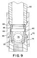
- washers 84 and 86 are shown and described above being used in conjunction with a ball stop washer 82, a ball stop pin 80 may alternately be employed in either an original or retrofit configuration with ball guide 89 as shown in Fig. 9.
- the present packing assembly permits the manufacture of a check valve having an adjustable ball lift without drilling or otherwise providing multiple sets of holes for ball stop pin positions. Additionally, the check valve may be easily interchanged between various ball lift heights using washers to adjust the height. Moreover, in an additional embodiment, by incorporating washers of non-uniform thicknesses, multiple ball lift heights may be achieved while using fewer washers than if uniform thickness washers are used.
- check valve having adjustable lift is shown and described as being used in the context of the foot valve of a reciprocating pump, it is envisaged that this valve may be used in other applications where it is desirable to selectively control the ball lift height of a check valve.
Landscapes
- Engineering & Computer Science (AREA)
- General Engineering & Computer Science (AREA)
- Mechanical Engineering (AREA)
- Check Valves (AREA)
- Details Of Reciprocating Pumps (AREA)
- Taps Or Cocks (AREA)
Abstract
Description
- This invention relates generally to fluid valves and more particularly to fluid valves having adjustable lifts for pumps.
- In hydraulic pumping systems, check valves are typically used to limit the direction of flow through a pump. As is known in the art, these valves include a ball closure element which, responsive to the direction of fluid movement through the valve, closes to prevent the passage of the fluid in one direction by moving into engagement with a valve seat and opens to permit the passage of the fluid in an opposite direction by moving away from the valve seat. In order to control the amount of fluid pressure that is permitted to flow through a valve, a ball stop element is generally used to limit the distance, commonly referred to as "lift," to which the ball closure element is permitted to move away from the valve seat.
- An exemplary pump having check valves with ball stops that limit the lift of a ball closure element is shown in US-A-5,647,737. A two-ball style pump available from Ingersoll-Rand Company, Woodcliff Lake, NJ as the ARO Model 66475 pump incorporates such check valves having a ball closure element located within a cylindrical ball guide in its lower pump end to control the inlet flow of a fluid to be pumped into the pump. A pin positioned in holes located in a ball guide is used as a ball stop element to increase or decrease the lift of the ball valve element in the valve body. If more ball lift is desired for heavier (i.e., more viscous) fluids, the pin is moved to holes in the ball guide that are further away from the valve seat. Conversely, if less ball lift is desired for lighter (i.e., less viscous) materials, the pin is moved to holes located closer to the valve seat in the ball guide.
- Manufacturing such check valves with adjustable lifts, however, require drilling or otherwise providing multiple sets of holes in the cylindrical ball guide for providing multiple positions into which a ball stop pin could be inserted.
- According to one aspect of the present invention, there is provided a packing assembly for a check valve, characterised by a ball stop member having opposed first and second contact portions, and at least two washers being provided in a stacking configuration selected from one in which all of the at least two washers are stacked against the first contact portion of the ball stop member, one in which all of the at least two washers are stacked against the second contact portion of the ball stop member, and one in which at least one of the at least two washers is stacked against the first contact portion of the ball stop member and at least one of the at least two washers is stacked against the second contact portion of the ball stop member.
- According to a second aspect of the present invention, there is provided a check valve assembly for a pump, comprising a check ball, a ball stop member having opposed first and second contact portions, and at least two washers being provided in a stacking configuration selected from one in which all of the at least two washers are stacked against the first contact portion of the ball stop member, one in which all of the at least two washers are stacked against the second contact portion of the ball stop member, and one in which at least one of the at least two washers is stacked against the first contact portion of the ball stop member and at least one of the at least two washers is stacked against the second contact portion of the ball stop member.
- According to a third aspect of the present invention, there is provided a packing assembly retrofit kit for a for a check valve, comprising a ball stop member having opposed first and second contact portions, and at least two washers being provided in a stacking configuration selected from one in which all of the at least two washers are stacked against the first contact portion of the ball stop member, one in which all of the at least two washers are stacked against the second contact portion of the ball stop member, and one in which at least one of the at least two washers is stacked against the first contact portion of the ball stop member and at least one of the at least two washers is stacked against the second contact portion of the ball stop member.
- For a better understanding of the invention and to show how the same may be carried into effect, reference will now be made, by way of example, to the accompanying drawings, in which:-
- Fig. 1 is a cross-sectional view of a reciprocating pump having a conventional check valve with a ball stop pin having adjustable lift positions;
- Fig. 2 is a cross-sectional view of the reciprocating pump shown in Fig. 2 having a conventional check valve with the ball stop pin removed;
- Fig. 3 is a cross-sectional view of a reciprocating pump having a check valve with adjustable lift positions according to one embodiment of the present invention;
- Fig. 4 is a planar view of a ball stop washer according to the present invention;
- Figs. 5-8 are exploded elevational views illustrating different stacking arrangements of washers according to one embodiment of the present invention; and
- Fig. 9 is a cross-sectional view of a reciprocating pump having a check valve with adjustable lift positions according to another embodiment of the present invention.
-
- Shown in Figures 1 and 2 is a
conventional foot valve 70 attached to anelongate pump tube 62 of a reciprocating pump (not shown) well known to one skilled in the relevant art.Foot valve 70 includes a check valve having acheck ball 74. seated incheck valve seat 76 which is held by afoot valve body 75 into which fluid to be pumped enters at the bottom. Attached tofoot valve body 75 is aball guide 79 in whichcheck ball 74 moves into and out of sealing engagement withcheck valve seat 76.Foot valve body 70 is threadingly attached topump tube 62 by a threadedsleeve 69. As shown in Fig. 1, aball stop pin 80 is passed throughcircular openings 81 formed inball guide 79. As shown in greater detail in Fig. 2 in which theball stop pin 80 has been removed, multiple pairs ofcylindrical openings 81 are provided for positioning theball stop pin 80. By movingball stop pin 80 tocylindrical holes 81 closer or further away fromcheck valve seat 76, the length of travel of thecheck valve ball 74 shown by the phantom ball positions in Fig. 2 can be respectively decreased or increased to selectively adjust the ball lift height. - Shown in Fig. 3 is the
foot valve 70 of Figs. 1 and 2 that has been modified to include a check valve having adjustable lift according to one embodiment of the present invention. The check valve includes aball stop washer 82 having across-member 83 that preferably passes diametrically through the washer opening as shown in Fig. 4. As shown in Fig. 3 acylindrical ball guide 89 is used in conjunction with a packing assembly having at least twowashers ball stop washer 82 fromcheck valve seat 76. As shown in the exploded view of Figs.. 5-8, by varying the stacking arrangement ofwashers ball stop washer 82, the ball lift ofcheck ball 74 may be varied. By stackingwashers washers ball guide 89 andball stop washer 82 as shown in Fig. 8, the ball lift may be maximised. By stackingstacking washers ball stop washer 82 is located betweenball guide 89 andwashers - By disposing
washers washer 84 andwasher 86 are of different thicknesses to provide different intermediate lift heights when used on alternate sides ofball stop washer 82 as shown in Figs. 6 and 7. It is preferred that the thicknesses of the washers be multiples of one another to accomplish variable lifts using fewer washers than if uniform thickness washers are used. In a preferred embodiment,washer 86 is provided with a thickness that is twice the thickness ofwasher 84 thereby achieving the four graduated ball lift configurations shown in Figs. 5-8 while using one less washer than would be needed if washers of uniform thickness were used. - As described above,
washers ball stop washer 82 andball guide 89 as either original equipment or as part of a retrofit to an existing check valve assembly. The retrofit is easily accomplished by replacing theball guide 79 andball stop pin 80 withball guide 89 andball stop washer 82, respectively, and configuring the packingarrangement using washers washers ball stop washer 82, aball stop pin 80 may alternately be employed in either an original or retrofit configuration withball guide 89 as shown in Fig. 9. - Thus, the present packing assembly permits the manufacture of a check valve having an adjustable ball lift without drilling or otherwise providing multiple sets of holes for ball stop pin positions. Additionally, the check valve may be easily interchanged between various ball lift heights using washers to adjust the height. Moreover, in an additional embodiment, by incorporating washers of non-uniform thicknesses, multiple ball lift heights may be achieved while using fewer washers than if uniform thickness washers are used.
- Although the check valve having adjustable lift is shown and described as being used in the context of the foot valve of a reciprocating pump, it is envisaged that this valve may be used in other applications where it is desirable to selectively control the ball lift height of a check valve.
Claims (14)
- A packing assembly for a check valve, characterised by:a ball stop member (82) having opposed first and second contact portions; andat least two washers (84, 86) being provided in a stacking configuration selected fromone in which all of the at least two washers are stacked against the first contact portion of the ball stop member; one in which all of the at least two washers are stacked against the second contact portion of the ball stop member; andone in which at least one of the at least two washers is stacked against the first contact portion of the ball stop member and at least one of the at least two washers is stacked against the second contact portion of the ball stop member.
- A packing assembly according to claim 1, wherein the at least two washers (84, 86) are of different thicknesses.
- A packing assembly according to claim 2, wherein the thicknesses of the at least two washers are multiples of each other.
- A packing assembly according to claim 3, wherein the at least two washers comprise a first washer and a second washer, the second washer (86) having a thickness that is twice the thickness of the first washer (84).
- A packing assembly according to any one of the preceding claims, wherein the ball stop member is a ball stop pin (80) or a ball stop washer (82).
- A check valve assembly for a pump, comprising:a check ball (74);a ball stop member (82) having opposed first and second contact portions; andat least two washers (84, 86) being provided in a stacking configuration selected fromone in which all of the at least two washers are stacked against the first contact portion of the ball stop member; one in which all of the at least two washers are stacked against the second contact portion of the ball stop member; andone in which at least one of the at least two washers is stacked against the first contact portion of the ball stop member and at least one of the at least two washers is stacked against the second contact portion of the ball stop member.
- An assembly according to claim 6, wherein the at least two washers (84, 86) are of different thicknesses.
- An assembly according to claim 7, wherein the thicknesses of the at least two washers are multiples of each other.
- An assembly according to claim 8, wherein the at least two washers comprise a first washer and a second washer, the second washer (86) having a thickness that is twice the thickness of the first washer (84).
- An assembly according to any one of claims 6 to 9, wherein the ball stop member is a ball stop pin (80) or a ball stop washer (82).
- A packing assembly retrofit kit for a for a check valve, comprising:a ball stop member having opposed first and second contact portions, andat least two washers being provided in a stacking configuration selected fromone in which all of the at least two washers are stacked against the first contactportion of the ball stop member;one in which all of the at least two washers are stacked against the second contact portion of the ball stop member; andone in which at least one of the at least two washers is stacked against the first contact portion of the ball stop member and at least one of the at least two washers is stacked against the second contact portion of the ball stop member.
- A retrofit kit according to claim 11, wherein the at least two washers are of different thicknesses.
- A retrofit kit according to claim 12, wherein the thicknesses of the at least two washers are multiples of each other.
- A retrofit kit according to claim 13, wherein the at least two washers comprise a first washer and a second washer, the second washer (86) having a thickness that is twice the thickness of the first washer (84).
Applications Claiming Priority (2)
| Application Number | Priority Date | Filing Date | Title |
|---|---|---|---|
| US27680 | 1979-04-06 | ||
| US10/027,680 US6619316B2 (en) | 2001-12-20 | 2001-12-20 | Check valve having adjustable lift, packing assembly, and retrofit kit for same |
Publications (1)
| Publication Number | Publication Date |
|---|---|
| EP1333206A1 true EP1333206A1 (en) | 2003-08-06 |
Family
ID=21839166
Family Applications (1)
| Application Number | Title | Priority Date | Filing Date |
|---|---|---|---|
| EP20020258420 Withdrawn EP1333206A1 (en) | 2001-12-20 | 2002-12-05 | Check valve having adjustable lift, packing assembly, and retrofit kit for same |
Country Status (3)
| Country | Link |
|---|---|
| US (1) | US6619316B2 (en) |
| EP (1) | EP1333206A1 (en) |
| CA (1) | CA2413392C (en) |
Cited By (4)
| Publication number | Priority date | Publication date | Assignee | Title |
|---|---|---|---|---|
| WO2016175936A1 (en) * | 2015-04-29 | 2016-11-03 | Graco Minnesota Inc. | Cartridge style ball check for positive displacement pump |
| CN108571603A (en) * | 2017-07-12 | 2018-09-25 | 杭州南方赛珀工业设备有限公司 | It is a kind of to fix hinged check valve |
| EP3404232B1 (en) | 2017-05-15 | 2019-11-13 | ECO Holding 1 GmbH | Connecting rod for a combustion engine with variable compression |
| WO2020229653A1 (en) * | 2019-05-16 | 2020-11-19 | Exel Industries | Pump for a system for applying a coating product, and use of such a pump |
Families Citing this family (14)
| Publication number | Priority date | Publication date | Assignee | Title |
|---|---|---|---|---|
| US20060081293A1 (en) * | 2004-10-18 | 2006-04-20 | Santa Cruz Cathy D | Control valve for backwash prevention |
| US20060097209A1 (en) * | 2004-11-09 | 2006-05-11 | Barron Luis F | Ball retainer for vehicle solenoid valve |
| US20070234997A1 (en) * | 2006-04-06 | 2007-10-11 | Prenger Nicholas J | Turbocharger oil supply passage check valve and method |
| US20080011487A1 (en) * | 2006-07-13 | 2008-01-17 | Blackhawk Environmental Co. | Drive piston and foot valve seat |
| US8312889B2 (en) * | 2009-06-30 | 2012-11-20 | Snyder Industries, Inc. | Combination flow control valve and reverse flow check valve |
| US8985145B2 (en) | 2013-03-11 | 2015-03-24 | Snyder Industries, Inc. | Combination flow control valve and reverse flow check valve |
| CA3012065A1 (en) * | 2017-07-21 | 2019-01-21 | Global Oil And Gas Supplies Inc. | Ball valve cage assembly for reciprocating downhole pump |
| JP2019039541A (en) * | 2017-08-29 | 2019-03-14 | 日本電産トーソク株式会社 | Hydraulic control device |
| US10801493B2 (en) | 2017-12-14 | 2020-10-13 | William E. Howseman, Jr. | Positive displacement reciprocating pump assembly for dispensing predeterminedly precise amounts of fluid during both the up and down strokes of the pump piston |
| US11079033B2 (en) * | 2019-03-05 | 2021-08-03 | Graco Minnesota Inc. | Check valve ball stop having gasket compression stand off |
| CA3193573A1 (en) * | 2020-09-23 | 2022-03-31 | Elkhart Plastics, Inc. | Intermediate bulk container, valve and connector system |
| US11725641B2 (en) | 2020-10-29 | 2023-08-15 | William E. Howseman, Jr. | Double-acting reciprocating pump assembly for use in conjunction with a melter |
| CN112943983A (en) * | 2021-04-16 | 2021-06-11 | 淮安市威力泵业科技有限公司 | Valve limiting sleeve and split type valve limiting sleeve |
| CN120368070B (en) * | 2025-06-19 | 2025-08-19 | 烟台卓信精密机械有限公司 | A throttling one-way valve |
Citations (3)
| Publication number | Priority date | Publication date | Assignee | Title |
|---|---|---|---|---|
| US5593292A (en) * | 1994-05-04 | 1997-01-14 | Ivey; Ray K. | Valve cage for a rod drawn positive displacement pump |
| US6123102A (en) * | 1993-08-23 | 2000-09-26 | Loegel, Sr.; Charles | High pressure shut-off valve |
| WO2003001095A1 (en) * | 2001-06-21 | 2003-01-03 | Graco Minnesota Inc. | Reciprocating piston pump adjustable inlet ball travel |
Family Cites Families (14)
| Publication number | Priority date | Publication date | Assignee | Title |
|---|---|---|---|---|
| US2899974A (en) * | 1959-08-18 | Non-return ball valve forreciprocat- | ||
| US487298A (en) * | 1892-12-06 | Check-valve | ||
| US1642724A (en) * | 1924-04-12 | 1927-09-20 | Worthington Pump & Machinery C | Valve |
| US2591174A (en) * | 1946-02-12 | 1952-04-01 | John N Martin | Well pump valve |
| US2536836A (en) * | 1947-05-05 | 1951-01-02 | Leonard C Bowling | Valve |
| US2590244A (en) * | 1948-02-21 | 1952-03-25 | Dixon T Harbison | Valve cage |
| GB1524255A (en) * | 1975-09-04 | 1978-09-06 | Jwi Ltd | Automatic vacuum stabilizing valve |
| US4722672A (en) | 1983-02-17 | 1988-02-02 | Rinneer Arthur E | Hydraulic energy-conversion device |
| US4683910A (en) * | 1984-05-04 | 1987-08-04 | Mks Instruments, Inc. | High-speed protective check valving for pressure transducers and the like |
| US4775303A (en) | 1985-02-08 | 1988-10-04 | Miroslav Liska | Pump having adjustable packing |
| AT403947B (en) | 1994-07-15 | 1998-06-25 | Hoerbiger Ventilwerke Ag | DISC VALVE |
| US5647737A (en) | 1996-02-20 | 1997-07-15 | Ingersoll-Rand Company | Reciprocating pump with simplified seal replacement |
| US5813483A (en) | 1996-12-16 | 1998-09-29 | Latham; James A. | Safety device for use on drilling rigs and process of running large diameter pipe into a well |
| US6105610A (en) | 1998-02-13 | 2000-08-22 | Liquid Metronics Incorporated | Cartridge valve with triple sequential seal |
-
2001
- 2001-12-20 US US10/027,680 patent/US6619316B2/en not_active Expired - Lifetime
-
2002
- 2002-12-03 CA CA2413392A patent/CA2413392C/en not_active Expired - Fee Related
- 2002-12-05 EP EP20020258420 patent/EP1333206A1/en not_active Withdrawn
Patent Citations (3)
| Publication number | Priority date | Publication date | Assignee | Title |
|---|---|---|---|---|
| US6123102A (en) * | 1993-08-23 | 2000-09-26 | Loegel, Sr.; Charles | High pressure shut-off valve |
| US5593292A (en) * | 1994-05-04 | 1997-01-14 | Ivey; Ray K. | Valve cage for a rod drawn positive displacement pump |
| WO2003001095A1 (en) * | 2001-06-21 | 2003-01-03 | Graco Minnesota Inc. | Reciprocating piston pump adjustable inlet ball travel |
Cited By (8)
| Publication number | Priority date | Publication date | Assignee | Title |
|---|---|---|---|---|
| WO2016175936A1 (en) * | 2015-04-29 | 2016-11-03 | Graco Minnesota Inc. | Cartridge style ball check for positive displacement pump |
| US10184577B2 (en) | 2015-04-29 | 2019-01-22 | Graco Minnesota, Inc. | Cartridge style ball check for positive displacement pump |
| EP3404232B1 (en) | 2017-05-15 | 2019-11-13 | ECO Holding 1 GmbH | Connecting rod for a combustion engine with variable compression |
| CN108571603A (en) * | 2017-07-12 | 2018-09-25 | 杭州南方赛珀工业设备有限公司 | It is a kind of to fix hinged check valve |
| CN108571603B (en) * | 2017-07-12 | 2024-01-09 | 杭州南方赛珀工业设备有限公司 | Fixed articulated check valve |
| WO2020229653A1 (en) * | 2019-05-16 | 2020-11-19 | Exel Industries | Pump for a system for applying a coating product, and use of such a pump |
| FR3096095A1 (en) * | 2019-05-16 | 2020-11-20 | Exel Industries | Pump for a coating material application system and use of such a pump |
| CN113710892A (en) * | 2019-05-16 | 2021-11-26 | 艾克赛尔工业公司 | Pump for a system for applying a coating product and use of such a pump |
Also Published As
| Publication number | Publication date |
|---|---|
| US6619316B2 (en) | 2003-09-16 |
| CA2413392C (en) | 2010-11-02 |
| CA2413392A1 (en) | 2003-06-20 |
| US20030116198A1 (en) | 2003-06-26 |
Similar Documents
| Publication | Publication Date | Title |
|---|---|---|
| CA2413392C (en) | Check valve having adjustable lift, packing assembly and retrofit kit for same | |
| DE102007030311B4 (en) | diaphragm pump | |
| US9551427B2 (en) | Valve device | |
| CA2233938C (en) | Diaphragm pump with chip resistant valve seats and low velocity check valves | |
| US5800136A (en) | Pump with bypass valve | |
| US6029685A (en) | Cage assembly for ball check valves | |
| KR900700812A (en) | Hydraulic Pilot Valve Device | |
| EP0592538B1 (en) | Recirculation valve | |
| CN1451888A (en) | Electric controlled hydraulic actuator with force feedback position detection | |
| JP4081437B2 (en) | Reciprocating piston pump with adjustable inlet ball travel | |
| WO2018054603A1 (en) | Damping valve for a vibration damper | |
| JPH0438158Y2 (en) | ||
| CN101115922A (en) | hydraulic piston pump | |
| CN100360799C (en) | Double-acting single-plunger pump with two-way valve | |
| CN113944664B (en) | Control valve with radial recesses in the region of a first orifice plate and a second orifice plate | |
| CN108397571B (en) | Rotary reversing valve | |
| DE1653577A1 (en) | Hydraulic pump in the manner of a pulsating diaphragm pump | |
| DE69400671T2 (en) | Check valve insert with spring valve | |
| CN101479482B (en) | Hydraulic pump | |
| KR20200126853A (en) | Relief Valve | |
| DE3636348A1 (en) | REDUCING VALVE | |
| DE602005000391T2 (en) | Valve for use in implantable infusion pumps | |
| CN2690642Y (en) | Hydraulic integrated block | |
| CN219692354U (en) | Check valve assembly and balance valve with same | |
| CN116447187B (en) | Bypass flow valve |
Legal Events
| Date | Code | Title | Description |
|---|---|---|---|
| PUAI | Public reference made under article 153(3) epc to a published international application that has entered the european phase |
Free format text: ORIGINAL CODE: 0009012 |
|
| AK | Designated contracting states |
Designated state(s): AT BE BG CH CY CZ DE DK EE ES FI FR GB GR IE IT LI LU MC NL PT SE SI SK TR |
|
| AX | Request for extension of the european patent |
Extension state: AL LT LV MK RO |
|
| 17P | Request for examination filed |
Effective date: 20040123 |
|
| AKX | Designation fees paid |
Designated state(s): DE FR GB |
|
| 17Q | First examination report despatched |
Effective date: 20040318 |
|
| GRAP | Despatch of communication of intention to grant a patent |
Free format text: ORIGINAL CODE: EPIDOSNIGR1 |
|
| RTI1 | Title (correction) |
Free format text: CHECK VALVE ASSEMBLY FOR A PUMP |
|
| GRAS | Grant fee paid |
Free format text: ORIGINAL CODE: EPIDOSNIGR3 |
|
| STAA | Information on the status of an ep patent application or granted ep patent |
Free format text: STATUS: THE APPLICATION HAS BEEN WITHDRAWN |
|
| 18W | Application withdrawn |
Effective date: 20060104 |