EP1333151A2 - Liner of optimized thickness for positive displacement drilling motors - Google Patents
Liner of optimized thickness for positive displacement drilling motors Download PDFInfo
- Publication number
- EP1333151A2 EP1333151A2 EP03250171A EP03250171A EP1333151A2 EP 1333151 A2 EP1333151 A2 EP 1333151A2 EP 03250171 A EP03250171 A EP 03250171A EP 03250171 A EP03250171 A EP 03250171A EP 1333151 A2 EP1333151 A2 EP 1333151A2
- Authority
- EP
- European Patent Office
- Prior art keywords
- liner
- thickness
- stator
- radially inwardly
- inwardly projecting
- Prior art date
- Legal status (The legal status is an assumption and is not a legal conclusion. Google has not performed a legal analysis and makes no representation as to the accuracy of the status listed.)
- Granted
Links
Images
Classifications
-
- E—FIXED CONSTRUCTIONS
- E21—EARTH OR ROCK DRILLING; MINING
- E21B—EARTH OR ROCK DRILLING; OBTAINING OIL, GAS, WATER, SOLUBLE OR MELTABLE MATERIALS OR A SLURRY OF MINERALS FROM WELLS
- E21B4/00—Drives for drilling, used in the borehole
- E21B4/02—Fluid rotary type drives
-
- F—MECHANICAL ENGINEERING; LIGHTING; HEATING; WEAPONS; BLASTING
- F03—MACHINES OR ENGINES FOR LIQUIDS; WIND, SPRING, OR WEIGHT MOTORS; PRODUCING MECHANICAL POWER OR A REACTIVE PROPULSIVE THRUST, NOT OTHERWISE PROVIDED FOR
- F03C—POSITIVE-DISPLACEMENT ENGINES DRIVEN BY LIQUIDS
- F03C2/00—Rotary-piston engines
- F03C2/08—Rotary-piston engines of intermeshing-engagement type, i.e. with engagement of co- operating members similar to that of toothed gearing
-
- F—MECHANICAL ENGINEERING; LIGHTING; HEATING; WEAPONS; BLASTING
- F04—POSITIVE - DISPLACEMENT MACHINES FOR LIQUIDS; PUMPS FOR LIQUIDS OR ELASTIC FLUIDS
- F04C—ROTARY-PISTON, OR OSCILLATING-PISTON, POSITIVE-DISPLACEMENT MACHINES FOR LIQUIDS; ROTARY-PISTON, OR OSCILLATING-PISTON, POSITIVE-DISPLACEMENT PUMPS
- F04C2/00—Rotary-piston machines or pumps
- F04C2/08—Rotary-piston machines or pumps of intermeshing-engagement type, i.e. with engagement of co-operating members similar to that of toothed gearing
- F04C2/10—Rotary-piston machines or pumps of intermeshing-engagement type, i.e. with engagement of co-operating members similar to that of toothed gearing of internal-axis type with the outer member having more teeth or tooth-equivalents, e.g. rollers, than the inner member
- F04C2/107—Rotary-piston machines or pumps of intermeshing-engagement type, i.e. with engagement of co-operating members similar to that of toothed gearing of internal-axis type with the outer member having more teeth or tooth-equivalents, e.g. rollers, than the inner member with helical teeth
- F04C2/1071—Rotary-piston machines or pumps of intermeshing-engagement type, i.e. with engagement of co-operating members similar to that of toothed gearing of internal-axis type with the outer member having more teeth or tooth-equivalents, e.g. rollers, than the inner member with helical teeth the inner and outer member having a different number of threads and one of the two being made of elastic materials, e.g. Moineau type
- F04C2/1073—Rotary-piston machines or pumps of intermeshing-engagement type, i.e. with engagement of co-operating members similar to that of toothed gearing of internal-axis type with the outer member having more teeth or tooth-equivalents, e.g. rollers, than the inner member with helical teeth the inner and outer member having a different number of threads and one of the two being made of elastic materials, e.g. Moineau type where one member is stationary while the other member rotates and orbits
- F04C2/1075—Construction of the stationary member
Definitions
- the invention relates generally to stators for use with positive displacement drilling motors. More specifically, the invention relates to selecting an optimized liner thickness for a stator so as to increase the power available from a positive displacement motor while increasing longevity of the stator.
- PDMs Positive Displacement Motors
- Moineau principle wherein pressurized fluid is forced though a series of channels formed on a rotor and a stator.
- the channels are generally helical in shape and may extend the entire length of the rotor and stator.
- the passage of the pressurized fluid generally causes the rotor to rotate within the stator.
- a substantially continuous seal may be formed between the rotor and the stator, and the pressurized fluid may act against the rotor proximate the sealing surfaces so as to impart rotational motion on the rotor as the pressurized fluid passes through the helical channels.
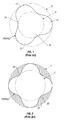
- a typical rotor 10 includes at least one lobe 12 (wherein, for example, channels 14 are formed between lobes 12 ), a major diameter 8 , and a minor diameter 6 .
- the rotor 10 may be formed of metal or any other suitable material.
- the rotor 10 may also be coated to withstand harsh drilling environments experienced downhole.
- a typical stator 20 comprises at least two lobes 22 , a major diameter 7 , and a minor diameter 5 . Note that if the rotor ( 10 in Figure 1) includes "n" lobes, the corresponding stator 20 used in combination with the rotor 10 generally includes either "n+1" or "n-1" lobes.
- the stator 20 generally includes a cylindrical external tube 24 and a liner 26 .
- the liner 26 may be formed from an elastomer, plastic, or other synthetic or natural material known in the art.
- the liner 26 is typically injected into the cylindrical external tube 24 around a mold (not shown) that has been placed therein.
- the liner 26 is then cured for a selected time at a selected temperature (or temperatures) before the mold (not shown) is removed.
- a thickness 28 of the liner 26 is generally controlled by changing the dimensions of the mold (not shown).
- a lower end of the rotor may be coupled either directly or indirectly to, for example, a drill bit.
- the PDM provides a drive mechanism for a drill bit independent of any rotational motion of a drillstring generated proximate the surface of the well by, for example, rotation of a rotary table on a drilling rig.
- PDMs are especially useful in drilling directional wells where a drill bit is connected to a lower end of a bottom hole assembly (BHA).
- the BHA may include, for example, a PDM, a transmission assembly, a bent housing assembly, a bearing section, and the drill bit.
- the rotor may transmit torque to the drill bit via a drive shaft or a series of drive shafts that are operatively coupled to the rotor and to the drill bit. Therefore, when directionally drilling a wellbore, the drilling action is typically referred to as "sliding" because the drill string slides through the wellbore rather than rotating through the wellbore (as would be the case if the drill string were rotated using a rotary table) because rotary motion of the drill bit is produced by the PDM.
- directional drilling may also be performed by rotating the drill string and using the PDM, thereby increasing the available torque and drill bit rpm.
- a rotational frequency and, for example, an amount of torque generated by the rotation of the rotor within the stator may be selected by determining a number of lobes on the rotor and stator, a major and minor diameter of the rotor and stator, and the like.
- An assembled view of a rotor and a stator is shown in Figure 3. Rotation of the rotor 10 within the stator 20 causes the rotor 10 to nutate within the stator 20 . Typically, a single nutation may be defined as when the rotor 10 moves one lobe width within the stator 20.
- the motion of the rotor 10 within the stator 20 may be defined by a circle O which defines a trajectory of a point A disposed on a rotor axis as point A moves around a stator axis B during a series of nutations.
- an "eccentricity" e of the assembly may be defined as a distance between the rotor axis A and the stator axis B when the rotor 10 and stator 20 are assembled to form a PDM.
- Typical stators known in the art are formed in a manner similar to that shown in Figure 2.
- an inner surface 29 of the external tube 24 is generally cylindrical in shape and the stator lobes 22 are formed by molding an elastomer in the external tube 24 .
- Problems may be encountered with the stator 20 when, for example, rotation of the rotor 10 within the stator 20 shears off portions of the stator lobes 22 . This process, which may be referred to as "chunking," deteriorates the seal formed between the rotor 10 and stator 20 and may cause failure of the PDM. Chunking may be increased by swelling of the liner 26 or thermal fatigue.
- Swelling and thermal fatigue may be caused by elevated temperatures and exposure to certain drilling fluids and formation fluids, among other factors.
- flexibility of the liner 26 may lead to incomplete sealing between the rotor 10 and stator 20 such that available torque may be lost when the rotor compresses the stator lobe material, thereby reducing the power output of the PDM. Accordingly, there is a need for a stator design that provides increased power output and increased longevity in harsh downhole environments.
- the invention comprises a stator for a positive displacement motor.
- the stator comprises an external tube comprising an outer surface and an inner surface, and the inner surface comprising at least two radially inwardly projecting lobes extending helically along a selected length of the external tube.
- a liner is disposed proximate the inner surface, and the liner conforms to the radially inwardly projecting lobes formed on the inner surface and to the helical shape of the inner surface.
- a thickness of the liner is at a maximum proximate the at least two radially inwardly projecting lobes.
- the invention comprises a positive displacement motor.
- the positive displacement motor comprises a stator including an external tube comprising an outer surface and an inner surface.
- the inner surface comprises at least two radially inwardly projecting lobes extending helically along a selected length of the external tube.
- a liner is disposed proximate the inner surface, and the liner conforms to the radially inwardly projecting lobes formed on the inner surface and to the helical shape of the inner surface.
- a thickness of the liner is at a maximum proximate the at least two radially inwardly projecting lobes.
- a rotor is disposed inside the stator, and the rotor comprises at least one radially outwardly projecting lobe extending helically along a selected length of the rotor.
- the at least one radially outwardly projecting lobe formed on the rotor is adapted to sealingly engage the at least two radially outwardly projecting lobes formed on the liner.
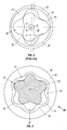
- FIG. 4 shows an embodiment comprising at least one aspect of the present invention.
- a positive displacement motor (PDM) 30 comprises a stator 32 and a rotor 34 .
- the stator 32 comprises an external tube 38 that may be formed from, for example, steel or another material suitable for downhole use in a drilling environment.
- the stator also comprises a liner 36 that may be formed from an elastomer, a plastic, or any other suitable synthetic or natural material known in the art.
- the liner may also be formed from a fiber reinforced material such as the materials described in co-pending U.S. Patent Application No. / , filed on even date herewith, and assigned to the assignee of the present application.
- the external tube 38 comprises a shaped inner surface 44 that comprises at least two lobes 46 formed thereon.
- the lobes 46 are helically formed along a selected length of the external tube 38 so that the lobes 46 define a helical pattern along the selected length.
- the helical form of the inner surface 44 generally corresponds to a desired shape for stator lobes.
- the liner 36 typically comprises at least two lobes 40 , and a thickness 42 of the liner 36 is nonuniform throughout a cross-section thereof.
- the lobes 40 (and the liner 36 ) are helically formed along a selected length of the external tube 38 such that the liner 36 conforms to the helically shaped inner surface 44 so that the at least two lobes 46 formed on the shaped inner surface 44 correspond to the lobes 40 formed in the liner 36 .
- the external tube 38 including the inner surface 44 , may be helically shaped by any means known in the art including machining, extrusion, and the like.
- the shaped inner surface 44 of the external tube 38 is adapted to provide additional support for the liner material.
- the shaped inner surface 44 "stiffens" the liner 36 by providing support for the liner 36 ( e.g ., by forming a metal backing), thereby increasing power available from the PDM.
- shaping the inner surface 44 to form a contoured backing for the liner 36 may stiffen the liner material proximate the lobes 40 by reducing an amount by which the liner 36 may be compressed when contacted by the rotor 44 so that a better seal may be formed between the rotor 44 and the stator 32 .
- reduced flexibility increases an amount of torque required to stall the PDM.
- the thickness 42 of the liner 36 may be increased at selected locations that are exposed to, for example, increased wear and shear (e.g ., proximate the lobes 40, 46 ), so that the longevity of the stator 32 and, therefore, the longevity of the PDM 30 may be increased.
- the thickness of the liner 36 is selected so as to maximize a shear strength of the liner 36 proximate the lobes 46 .
- the shaped form of the inner surface 44 typically results in a thinner liner 36 than is commonly used in prior art stators (such as that shown in Figure 2). Fluid pressure is less likely to deform the liner 36 and, accordingly, the liner 36 is less susceptible to deformation that could reduce the efficiency of the seal formed between the rotor 34 and stator 32 (thereby producing an additional loss in power output of the PDM 30).
- the thickness 42 of the liner 36 may be varied so that a thickness TA of the portion of the liner 36 proximate the lobes 46 is greater than a thickness of other portions of the liner 36 (e.g., a thickness TB of the portion of the liner 36 proximate channels 48 ).
- the thickness 42 of the liner 36 may be selected to generate a desired amount of contact (or, if desired, clearance) between the liner 36 and the rotor 34 .
- the thickness 42 of the liner 36 may be selected to form a seal between the rotor 34 and the stator 32 while maintaining a desired level of compression between the rotor 34 and stator 32 when they are in contact with each other.
- the thickness 42 of the liner 36 may be selected to permit, for example, swelling or contraction of the liner 36 caused by elevated temperatures, contact with drilling fluids and other fluids, and the like.
- the thickness TA of the liner 36 proximate the lobes 46 is selected to be at least 1.5 times the thickness TB of the liner 36 proximate the channels 48 . In other embodiments, the thickness TA of the liner 36 proximate the lobes 46 may be selected to be less than or equal to 3 times the thickness TB of the liner 36 proximate the channels 48 . Other embodiments may comprise other thickness ratios depending on the type of material (e.g. , elastomer, plastic, etc.) selected to form the liner 36 .
- the embodiment in Figure 4 is generally referred to as a "5:6" configuration including 5 lobes formed on the rotor and 6 lobes formed on the stator.
- Other embodiments may include any other rotor/stator combination known in the art, including 1:2, 3:4, 4:5, 7:8, and other arrangements.
- stators may generally be formed using "n+1" or "n-1" lobes, where "n” refers to a number of rotor lobes. Accordingly, the embodiment shown in Figure 4, and other embodiments described herein, are intended to clarify the invention and are not intended to limit the scope of the invention with respect to, for example, a number of or arrangement of lobes.
- the present invention allows for an inner surface of an external stator tube to be shaped so as to enable optimization of a liner thickness and to provide a stiff backing for the liner material. Optimizing liner thickness leads to increased power output and increased longevity of the power section.
Landscapes
- Engineering & Computer Science (AREA)
- Mechanical Engineering (AREA)
- Life Sciences & Earth Sciences (AREA)
- General Engineering & Computer Science (AREA)
- Geology (AREA)
- Mining & Mineral Resources (AREA)
- Combustion & Propulsion (AREA)
- Physics & Mathematics (AREA)
- Chemical & Material Sciences (AREA)
- Environmental & Geological Engineering (AREA)
- Fluid Mechanics (AREA)
- General Life Sciences & Earth Sciences (AREA)
- Geochemistry & Mineralogy (AREA)
- Applications Or Details Of Rotary Compressors (AREA)
- Rotary Pumps (AREA)
Abstract
Description
Claims (15)
- A stator for a positive displacement motor, the stator comprising:an external tube comprising an outer surface and an inner surface, the inner surface comprising at least two radially inwardly projecting lobes extending helically along a selected length of the external tube; anda liner disposed proximate the inner surface, the liner conforming to the radially inwardly projecting lobes formed on the inner surface and to the helical shape of the inner surface, wherein a thickness of the liner is at a maximum proximate the at least two radially inwardly projecting lobes.
- The stator of claim 1, wherein a thickness of the liner is selected to form a desired level of compression between the liner and a rotor.
- The stator of claim 1, wherein a thickness of the liner is selected to maximize a shear strength of the liner proximate the at least two radially inwardly projecting lobes.
- The stator of claim 1, wherein a thickness of the liner is selected so as to maximize a power output of a positive displacement motor.
- The stator of claim 1, wherein the inner surface is shaped so as to reduce an amount of fluid pressure deformation of the liner.
- The stator of claim 1, wherein a thickness of the liner proximate the at least two radially inwardly projecting lobes is at least 1.5 times a thickness of the liner proximate channels formed between the at least two radially inwardly projecting lobes.
- The stator of claim 1, wherein a thickness of the liner proximate the at least two radially inwardly projecting lobes is less than or equal to 3 times a thickness of the liner proximate channels formed between the at least two radially inwardly projecting lobes.
- A positive displacement motor comprising:a stator comprising an external tube comprising an outer surface and an inner surface, the inner surface comprising at least two radially inwardly projecting lobes extending helically along a selected length of the external tube, and a liner disposed proximate the inner surface, the liner conforming to the radially inwardly projecting lobes formed on the inner surface and to the helical shape of the inner surface, wherein a thickness of the liner is at a maximum proximate the at least two radially inwardly projecting lobes; anda rotor disposed inside the stator, the rotor comprising at least one radially outwardly projecting lobe extending helically along a selected length of the rotor, the at least one radially outwardly projecting lobe formed on the rotor adapted to sealingly engage the at least two radially outwardly projecting lobes formed on the liner.
- The positive displacement motor of claim 8, wherein a thickness of the liner is selected to form a desired level of compression between the liner and a rotor.
- The positive displacement motor of claim 8, wherein a thickness of the liner is selected to maximize a shear strength of the liner proximate the at least two radially inwardly projecting lobes.
- The positive displacement motor of claim 8, wherein a thickness of the liner is selected so as to maximize a power output of the positive displacement motor.
- The positive displacement motor of claim 8, wherein the inner surface is shaped so as to reduce an amount of fluid pressure deformation of the liner.
- The positive displacement motor of claim 8, wherein the inner surface is shaped so as to maximize a power output of the positive displacement motor.
- The positive displacement motor of claim 8, wherein a thickness of the liner proximate the at least two radially inwardly projecting lobes is at least 1.5 times a thickness of the liner proximate channels formed between the at least two radially inwardly projecting lobes.
- The positive displacement motor of claim 8, wherein a thickness of the liner proximate the at least two radially inwardly projecting lobes is less than or equal to 3 times a thickness of the liner proximate channels formed between the at least two radially inwardly projecting lobes.
Applications Claiming Priority (2)
| Application Number | Priority Date | Filing Date | Title |
|---|---|---|---|
| US56135 | 2002-01-24 | ||
| US10/056,135 US6604921B1 (en) | 2002-01-24 | 2002-01-24 | Optimized liner thickness for positive displacement drilling motors |
Publications (3)
| Publication Number | Publication Date |
|---|---|
| EP1333151A2 true EP1333151A2 (en) | 2003-08-06 |
| EP1333151A3 EP1333151A3 (en) | 2003-10-29 |
| EP1333151B1 EP1333151B1 (en) | 2005-06-15 |
Family
ID=22002394
Family Applications (1)
| Application Number | Title | Priority Date | Filing Date |
|---|---|---|---|
| EP03250171A Expired - Lifetime EP1333151B1 (en) | 2002-01-24 | 2003-01-10 | Liner of optimized thickness for positive displacement drilling motors |
Country Status (4)
| Country | Link |
|---|---|
| US (1) | US6604921B1 (en) |
| EP (1) | EP1333151B1 (en) |
| CA (1) | CA2411535C (en) |
| DE (1) | DE60300825D1 (en) |
Cited By (2)
| Publication number | Priority date | Publication date | Assignee | Title |
|---|---|---|---|---|
| EP2453137A3 (en) * | 2010-11-13 | 2016-06-15 | Artemis Kautschuk- und Kunststoff-Technik GmbH | Stator of an eccentric screw pump |
| CN109236559A (en) * | 2018-08-20 | 2019-01-18 | 中海石油(中国)有限公司上海分公司 | A kind of screw motor and mud motor |
Families Citing this family (26)
| Publication number | Priority date | Publication date | Assignee | Title |
|---|---|---|---|---|
| US6604922B1 (en) * | 2002-03-14 | 2003-08-12 | Schlumberger Technology Corporation | Optimized fiber reinforced liner material for positive displacement drilling motors |
| CA2543554C (en) * | 2003-10-27 | 2010-03-09 | Dyna-Drill Technologies, Inc. | Asymmetric contouring of elastomer liner on lobes in a moineau style power section stator |
| US7517202B2 (en) * | 2005-01-12 | 2009-04-14 | Smith International, Inc. | Multiple elastomer layer progressing cavity stators |
| RU2373364C2 (en) * | 2005-12-14 | 2009-11-20 | Общество с ограниченной ответственностью "Фирма "Радиус-Сервис" | Stator of screw gerotor machine |
| RU2315201C1 (en) * | 2006-07-05 | 2008-01-20 | Общество с ограниченной ответственностью "Фирма "Радиус-Сервис" | Stator of screw gyrator hydraulic machine |
| US9163629B2 (en) * | 2006-07-31 | 2015-10-20 | Schlumberger Technology Corporation | Controlled thickness resilient material lined stator and method of forming |
| CA2673720C (en) * | 2007-01-24 | 2013-04-16 | Halliburton Energy Services, Inc. | Electroformed stator tube for a progressing cavity apparatus |
| US7878774B2 (en) * | 2007-06-05 | 2011-02-01 | Smith International, Inc. | Moineau stator including a skeletal reinforcement |
| US7950914B2 (en) * | 2007-06-05 | 2011-05-31 | Smith International, Inc. | Braze or solder reinforced Moineau stator |
| US8734141B2 (en) * | 2009-09-23 | 2014-05-27 | Halliburton Energy Services, P.C. | Stator/rotor assemblies having enhanced performance |
| US9393648B2 (en) | 2010-03-30 | 2016-07-19 | Smith International Inc. | Undercut stator for a positive displacment motor |
| US9168552B2 (en) | 2011-08-25 | 2015-10-27 | Smith International, Inc. | Spray system for application of adhesive to a stator tube |
| US8888474B2 (en) | 2011-09-08 | 2014-11-18 | Baker Hughes Incorporated | Downhole motors and pumps with asymmetric lobes |
| EP2817485B1 (en) | 2012-02-21 | 2021-05-12 | Services Pétroliers Schlumberger | Fiber reinforced elastomeric stator |
| US8985977B2 (en) | 2012-09-06 | 2015-03-24 | Baker Hughes Incorporated | Asymmetric lobes for motors and pumps |
| US9133841B2 (en) | 2013-04-11 | 2015-09-15 | Cameron International Corporation | Progressing cavity stator with metal plates having apertures with englarged ends |
| JP2017506308A (en) | 2014-02-18 | 2017-03-02 | バート ローターズ ユーケー リミテッドVert Rotors Uk Limited | Positive displacement rotary machine |
| US9896885B2 (en) | 2015-12-10 | 2018-02-20 | Baker Hughes Incorporated | Hydraulic tools including removable coatings, drilling systems, and methods of making and using hydraulic tools |
| RU2669438C1 (en) * | 2017-06-06 | 2018-10-11 | Общество с ограниченной ответственностью "Фирма "Радиус-Сервис" | Hydraulic downhole motor |
| RU2688824C1 (en) * | 2018-09-26 | 2019-05-22 | Общество с ограниченной ответственностью "Фирма "Радиус-Сервис" | Hydraulic downhole motor |
| RU2745677C1 (en) * | 2020-02-25 | 2021-03-30 | Общество с ограниченной ответственностью "Фирма "Радиус-Сервис" | Stator of screw gerotor hydraulic machine |
| EP4171934A4 (en) | 2020-06-30 | 2024-07-31 | Services Pétroliers Schlumberger | Over mandrel extrusion for composite pcp stator |
| DE102020004334A1 (en) | 2020-07-20 | 2022-01-20 | Wilhelm Kächele GmbH | Stator for progressing cavity machine |
| US12110892B2 (en) | 2020-08-21 | 2024-10-08 | Schlumberger Technology Corporation | System and methodology comprising composite stator for low flow electric submersible progressive cavity pump |
| DE102021130260A1 (en) | 2021-11-19 | 2023-05-25 | Wilhelm Kächele GmbH | Stator for eccentric screw machine and manufacturing method for this |
| US11913297B1 (en) * | 2022-12-22 | 2024-02-27 | Saudi Arabian Oil Company | Method and apparatus for deploying and cementing liners across challenging well profiles |
Family Cites Families (31)
| Publication number | Priority date | Publication date | Assignee | Title |
|---|---|---|---|---|
| US3417664A (en) | 1966-08-29 | 1968-12-24 | Black & Decker Mfg Co | Vane construction for pneumatic motor |
| DE2017620C3 (en) * | 1970-04-13 | 1981-07-16 | Gummi-Jäger KG GmbH & Cie, 3000 Hannover | Eccentric screw pump |
| FR2343906A1 (en) | 1976-03-09 | 1977-10-07 | Mecanique Metallurgie Ste Gle | IMPROVEMENTS TO SCREW PUMP STATORS |
| DE2713468C3 (en) * | 1977-03-26 | 1982-09-02 | Allweiler Ag, 7760 Radolfzell | Stator for progressing cavity pumps |
| US4173670A (en) | 1977-05-27 | 1979-11-06 | Exxon Research & Engineering Co. | Composite tubular elements |
| DE3525529C1 (en) | 1985-07-17 | 1986-08-07 | Netzsch-Mohnopumpen GmbH, 8264 Waldkraiburg | Stator for eccentric screw pumps |
| US4836759A (en) | 1985-11-08 | 1989-06-06 | Nautical Services Pty. Ltd. | Rotary pump with orbiting rotor of harder material than stator |
| US4676725A (en) | 1985-12-27 | 1987-06-30 | Hughes Tool Company | Moineau type gear mechanism with resilient sleeve |
| US5611397A (en) | 1994-02-14 | 1997-03-18 | Wood; Steven M. | Reverse Moineau motor and centrifugal pump assembly for producing fluids from a well |
| US6183226B1 (en) | 1986-04-24 | 2001-02-06 | Steven M. Wood | Progressive cavity motors using composite materials |
| GB2244517B (en) | 1990-05-31 | 1994-05-04 | Mono Pumps Ltd | Helical gear pump and stator |
| US5171138A (en) | 1990-12-20 | 1992-12-15 | Drilex Systems, Inc. | Composite stator construction for downhole drilling motors |
| DE4134853C1 (en) | 1991-05-22 | 1992-11-12 | Netzsch-Mohnopumpen Gmbh, 8264 Waldkraiburg, De | |
| US5248896A (en) * | 1991-09-05 | 1993-09-28 | Drilex Systems, Inc. | Power generation from a multi-lobed drilling motor |
| US5171139A (en) * | 1991-11-26 | 1992-12-15 | Smith International, Inc. | Moineau motor with conduits through the stator |
| DE4237966A1 (en) | 1992-11-11 | 1994-05-26 | Arnold Jaeger | Eccentric screw pump |
| US5759019A (en) | 1994-02-14 | 1998-06-02 | Steven M. Wood | Progressive cavity pumps using composite materials |
| US6461128B2 (en) | 1996-04-24 | 2002-10-08 | Steven M. Wood | Progressive cavity helical device |
| US5843374A (en) | 1996-10-11 | 1998-12-01 | Tetra Laval Holdings & Finance, Sa | Method and apparatus for sterilizing packaging |
| JP3522062B2 (en) | 1997-01-23 | 2004-04-26 | 鬼怒川ゴム工業株式会社 | Fiber reinforced rubber hose for automatic transmission |
| US6102681A (en) | 1997-10-15 | 2000-08-15 | Aps Technology | Stator especially adapted for use in a helicoidal pump/motor |
| DE19754818A1 (en) | 1997-12-10 | 1999-06-17 | Artemis Kautschuk Kunststoff | Process for the production of elastomer stators for eccentric screw pumps |
| EP1040275B1 (en) | 1997-12-18 | 2003-09-10 | Baker Hughes Incorporated | Method of making stators for moineau pumps |
| DE19804259A1 (en) | 1998-02-04 | 1999-08-12 | Artemis Kautschuk Kunststoff | Elastomer stator for eccentric screw pumps |
| US6120267A (en) | 1998-04-01 | 2000-09-19 | Robbins & Myers, Inc. | Progressing cavity pump including a stator modified to improve material handling capability |
| DE19821867A1 (en) * | 1998-05-15 | 1999-11-18 | Artemis Kautschuk Kunststoff | Downhole deep drilling motor based on eccentric mono-pump principle |
| US6309195B1 (en) | 1998-06-05 | 2001-10-30 | Halliburton Energy Services, Inc. | Internally profiled stator tube |
| DE19827101A1 (en) | 1998-06-18 | 1999-12-23 | Artemis Kautschuk Kunststoff | Machine used in deep drilling, especially in crude oil recovery |
| US6241494B1 (en) * | 1998-09-18 | 2001-06-05 | Schlumberger Technology Company | Non-elastomeric stator and downhole drilling motors incorporating same |
| WO2001044615A2 (en) * | 1999-11-10 | 2001-06-21 | Ewm Technology, Inc. | Composite stator for drilling motors and method of constructing same |
| DE20013030U1 (en) * | 2000-07-20 | 2000-12-07 | Artemis Kautschuk- und Kunststofftechnik GmbH & Cie, 30559 Hannover | Anti-rotation device for stators of eccentric screw pumps |
-
2002
- 2002-01-24 US US10/056,135 patent/US6604921B1/en not_active Expired - Lifetime
- 2002-11-07 CA CA002411535A patent/CA2411535C/en not_active Expired - Lifetime
-
2003
- 2003-01-10 DE DE60300825T patent/DE60300825D1/en not_active Expired - Lifetime
- 2003-01-10 EP EP03250171A patent/EP1333151B1/en not_active Expired - Lifetime
Cited By (2)
| Publication number | Priority date | Publication date | Assignee | Title |
|---|---|---|---|---|
| EP2453137A3 (en) * | 2010-11-13 | 2016-06-15 | Artemis Kautschuk- und Kunststoff-Technik GmbH | Stator of an eccentric screw pump |
| CN109236559A (en) * | 2018-08-20 | 2019-01-18 | 中海石油(中国)有限公司上海分公司 | A kind of screw motor and mud motor |
Also Published As
| Publication number | Publication date |
|---|---|
| EP1333151B1 (en) | 2005-06-15 |
| EP1333151A3 (en) | 2003-10-29 |
| DE60300825D1 (en) | 2005-07-21 |
| CA2411535A1 (en) | 2003-07-24 |
| US20030138338A1 (en) | 2003-07-24 |
| US6604921B1 (en) | 2003-08-12 |
| CA2411535C (en) | 2005-12-20 |
Similar Documents
| Publication | Publication Date | Title |
|---|---|---|
| US6604921B1 (en) | Optimized liner thickness for positive displacement drilling motors | |
| EP1344936B1 (en) | Fibre reinforced liner material for moineau-type motor and method of forming | |
| US5171138A (en) | Composite stator construction for downhole drilling motors | |
| RU2607833C2 (en) | Downhole motors and pumps with asymmetric helical teeth | |
| CA2397164C (en) | Progressive cavity helical device | |
| US6881045B2 (en) | Progressive cavity pump/motor | |
| CA3024018C (en) | Load balanced power section of progressing cavity device | |
| US11821288B2 (en) | Hydraulic tools, drilling systems including hydraulic tools, and methods of using hydraulic tools | |
| AU2013401963B2 (en) | Rotor bearing for progressing cavity downhole drilling motor | |
| US20130052067A1 (en) | Downhole Motors and Pumps with Improved Stators and Methods of Making and Using Same | |
| US20020074167A1 (en) | High speed positive displacement motor | |
| US20060182643A1 (en) | Progressing cavity stator having a plurality of cast longitudinal sections | |
| EP1406016A1 (en) | Progressive cavity pumps using composite materials | |
| CA1121212A (en) | Stator for a downhole fluid operated motor and method of assembling the same | |
| CA2058080C (en) | Composite stator construction for downhole drilling motors | |
| CA2271647A1 (en) | Machine operating according to the moineau principle, especially a drill motor for deep drilling | |
| GB2408776A (en) | Helical Moineau pump having small radius peaks on rotor and stator | |
| US20260071621A1 (en) | Progressive cavity fluid pump and associated methods |
Legal Events
| Date | Code | Title | Description |
|---|---|---|---|
| PUAI | Public reference made under article 153(3) epc to a published international application that has entered the european phase |
Free format text: ORIGINAL CODE: 0009012 |
|
| AK | Designated contracting states |
Designated state(s): AT BE CH CY DE DK ES FI FR GB GR IE IT LI LU MC NL PT SE TR |
|
| AX | Request for extension of the european patent |
Extension state: AL LT LV MK RO SI |
|
| PUAL | Search report despatched |
Free format text: ORIGINAL CODE: 0009013 |
|
| AK | Designated contracting states |
Kind code of ref document: A3 Designated state(s): AT BE CH CY DE DK ES FI FR GB GR IE IT LI LU MC NL PT SE TR |
|
| AX | Request for extension of the european patent |
Extension state: AL LT LV MK RO SI |
|
| RIC1 | Information provided on ipc code assigned before grant |
Ipc: 7E 21B 4/02 A Ipc: 7F 04C 2/00 B |
|
| 17P | Request for examination filed |
Effective date: 20040428 |
|
| 17Q | First examination report despatched |
Effective date: 20040601 |
|
| AKX | Designation fees paid |
Designated state(s): BE DE FR GB |
|
| GRAP | Despatch of communication of intention to grant a patent |
Free format text: ORIGINAL CODE: EPIDOSNIGR1 |
|
| RAP1 | Party data changed (applicant data changed or rights of an application transferred) |
Owner name: SCHLUMBERGER TECHNOLOGY B.V. Owner name: SERVICES PETROLIERS SCHLUMBERGER Owner name: SCHLUMBERGER HOLDINGS LIMITED |
|
| GRAS | Grant fee paid |
Free format text: ORIGINAL CODE: EPIDOSNIGR3 |
|
| GRAA | (expected) grant |
Free format text: ORIGINAL CODE: 0009210 |
|
| AK | Designated contracting states |
Kind code of ref document: B1 Designated state(s): BE DE FR GB |
|
| PG25 | Lapsed in a contracting state [announced via postgrant information from national office to epo] |
Ref country code: BE Free format text: LAPSE BECAUSE OF FAILURE TO SUBMIT A TRANSLATION OF THE DESCRIPTION OR TO PAY THE FEE WITHIN THE PRESCRIBED TIME-LIMIT Effective date: 20050615 |
|
| REG | Reference to a national code |
Ref country code: GB Ref legal event code: FG4D |
|
| REF | Corresponds to: |
Ref document number: 60300825 Country of ref document: DE Date of ref document: 20050721 Kind code of ref document: P |
|
| PG25 | Lapsed in a contracting state [announced via postgrant information from national office to epo] |
Ref country code: DE Free format text: LAPSE BECAUSE OF FAILURE TO SUBMIT A TRANSLATION OF THE DESCRIPTION OR TO PAY THE FEE WITHIN THE PRESCRIBED TIME-LIMIT Effective date: 20050916 |
|
| ET | Fr: translation filed | ||
| PLBE | No opposition filed within time limit |
Free format text: ORIGINAL CODE: 0009261 |
|
| STAA | Information on the status of an ep patent application or granted ep patent |
Free format text: STATUS: NO OPPOSITION FILED WITHIN TIME LIMIT |
|
| 26N | No opposition filed |
Effective date: 20060316 |
|
| REG | Reference to a national code |
Ref country code: FR Ref legal event code: PLFP Year of fee payment: 14 |
|
| REG | Reference to a national code |
Ref country code: FR Ref legal event code: PLFP Year of fee payment: 15 |
|
| PGFP | Annual fee paid to national office [announced via postgrant information from national office to epo] |
Ref country code: FR Payment date: 20170127 Year of fee payment: 15 |
|
| PGFP | Annual fee paid to national office [announced via postgrant information from national office to epo] |
Ref country code: GB Payment date: 20170131 Year of fee payment: 15 |
|
| GBPC | Gb: european patent ceased through non-payment of renewal fee |
Effective date: 20180110 |
|
| PG25 | Lapsed in a contracting state [announced via postgrant information from national office to epo] |
Ref country code: FR Free format text: LAPSE BECAUSE OF NON-PAYMENT OF DUE FEES Effective date: 20180131 |
|
| REG | Reference to a national code |
Ref country code: FR Ref legal event code: ST Effective date: 20180928 |
|
| PG25 | Lapsed in a contracting state [announced via postgrant information from national office to epo] |
Ref country code: GB Free format text: LAPSE BECAUSE OF NON-PAYMENT OF DUE FEES Effective date: 20180110 |
|
| P01 | Opt-out of the competence of the unified patent court (upc) registered |
Effective date: 20231208 |