EP1332938A2 - Electromagnetically actuatable valve device as well as an arrangement for driving such a valve device - Google Patents
Electromagnetically actuatable valve device as well as an arrangement for driving such a valve device Download PDFInfo
- Publication number
- EP1332938A2 EP1332938A2 EP02026734A EP02026734A EP1332938A2 EP 1332938 A2 EP1332938 A2 EP 1332938A2 EP 02026734 A EP02026734 A EP 02026734A EP 02026734 A EP02026734 A EP 02026734A EP 1332938 A2 EP1332938 A2 EP 1332938A2
- Authority
- EP
- European Patent Office
- Prior art keywords
- valve device
- arrangement
- magnetic coil
- valve
- electromagnet
- Prior art date
- Legal status (The legal status is an assumption and is not a legal conclusion. Google has not performed a legal analysis and makes no representation as to the accuracy of the status listed.)
- Withdrawn
Links
Images

Classifications
-
- F—MECHANICAL ENGINEERING; LIGHTING; HEATING; WEAPONS; BLASTING
- F16—ENGINEERING ELEMENTS AND UNITS; GENERAL MEASURES FOR PRODUCING AND MAINTAINING EFFECTIVE FUNCTIONING OF MACHINES OR INSTALLATIONS; THERMAL INSULATION IN GENERAL
- F16K—VALVES; TAPS; COCKS; ACTUATING-FLOATS; DEVICES FOR VENTING OR AERATING
- F16K31/00—Actuating devices; Operating means; Releasing devices
- F16K31/02—Actuating devices; Operating means; Releasing devices electric; magnetic
- F16K31/06—Actuating devices; Operating means; Releasing devices electric; magnetic using a magnet, e.g. diaphragm valves, cutting off by means of a liquid
- F16K31/0675—Electromagnet aspects, e.g. electric supply therefor
- F16K31/0679—Electromagnet aspects, e.g. electric supply therefor with more than one energising coil
-
- B—PERFORMING OPERATIONS; TRANSPORTING
- B60—VEHICLES IN GENERAL
- B60T—VEHICLE BRAKE CONTROL SYSTEMS OR PARTS THEREOF; BRAKE CONTROL SYSTEMS OR PARTS THEREOF, IN GENERAL; ARRANGEMENT OF BRAKING ELEMENTS ON VEHICLES IN GENERAL; PORTABLE DEVICES FOR PREVENTING UNWANTED MOVEMENT OF VEHICLES; VEHICLE MODIFICATIONS TO FACILITATE COOLING OF BRAKES
- B60T8/00—Arrangements for adjusting wheel-braking force to meet varying vehicular or ground-surface conditions, e.g. limiting or varying distribution of braking force
- B60T8/32—Arrangements for adjusting wheel-braking force to meet varying vehicular or ground-surface conditions, e.g. limiting or varying distribution of braking force responsive to a speed condition, e.g. acceleration or deceleration
- B60T8/34—Arrangements for adjusting wheel-braking force to meet varying vehicular or ground-surface conditions, e.g. limiting or varying distribution of braking force responsive to a speed condition, e.g. acceleration or deceleration having a fluid pressure regulator responsive to a speed condition
- B60T8/36—Arrangements for adjusting wheel-braking force to meet varying vehicular or ground-surface conditions, e.g. limiting or varying distribution of braking force responsive to a speed condition, e.g. acceleration or deceleration having a fluid pressure regulator responsive to a speed condition including a pilot valve responding to an electromagnetic force
- B60T8/3615—Electromagnetic valves specially adapted for anti-lock brake and traction control systems
- B60T8/363—Electromagnetic valves specially adapted for anti-lock brake and traction control systems in hydraulic systems
- B60T8/3645—Electromagnetic valves specially adapted for anti-lock brake and traction control systems in hydraulic systems having more than one electromagnetic coil inside a common housing
-
- B—PERFORMING OPERATIONS; TRANSPORTING
- B60—VEHICLES IN GENERAL
- B60T—VEHICLE BRAKE CONTROL SYSTEMS OR PARTS THEREOF; BRAKE CONTROL SYSTEMS OR PARTS THEREOF, IN GENERAL; ARRANGEMENT OF BRAKING ELEMENTS ON VEHICLES IN GENERAL; PORTABLE DEVICES FOR PREVENTING UNWANTED MOVEMENT OF VEHICLES; VEHICLE MODIFICATIONS TO FACILITATE COOLING OF BRAKES
- B60T8/00—Arrangements for adjusting wheel-braking force to meet varying vehicular or ground-surface conditions, e.g. limiting or varying distribution of braking force
- B60T8/32—Arrangements for adjusting wheel-braking force to meet varying vehicular or ground-surface conditions, e.g. limiting or varying distribution of braking force responsive to a speed condition, e.g. acceleration or deceleration
- B60T8/34—Arrangements for adjusting wheel-braking force to meet varying vehicular or ground-surface conditions, e.g. limiting or varying distribution of braking force responsive to a speed condition, e.g. acceleration or deceleration having a fluid pressure regulator responsive to a speed condition
- B60T8/36—Arrangements for adjusting wheel-braking force to meet varying vehicular or ground-surface conditions, e.g. limiting or varying distribution of braking force responsive to a speed condition, e.g. acceleration or deceleration having a fluid pressure regulator responsive to a speed condition including a pilot valve responding to an electromagnetic force
- B60T8/3615—Electromagnetic valves specially adapted for anti-lock brake and traction control systems
- B60T8/3655—Continuously controlled electromagnetic valves
- B60T8/366—Valve details
- B60T8/367—Seat valves, e.g. poppet valves
-
- F—MECHANICAL ENGINEERING; LIGHTING; HEATING; WEAPONS; BLASTING
- F15—FLUID-PRESSURE ACTUATORS; HYDRAULICS OR PNEUMATICS IN GENERAL
- F15B—SYSTEMS ACTING BY MEANS OF FLUIDS IN GENERAL; FLUID-PRESSURE ACTUATORS, e.g. SERVOMOTORS; DETAILS OF FLUID-PRESSURE SYSTEMS, NOT OTHERWISE PROVIDED FOR
- F15B13/00—Details of servomotor systems ; Valves for servomotor systems
- F15B13/02—Fluid distribution or supply devices characterised by their adaptation to the control of servomotors
- F15B13/04—Fluid distribution or supply devices characterised by their adaptation to the control of servomotors for use with a single servomotor
- F15B13/044—Fluid distribution or supply devices characterised by their adaptation to the control of servomotors for use with a single servomotor operated by electrically-controlled means, e.g. solenoids, torque-motors
- F15B13/0442—Fluid distribution or supply devices characterised by their adaptation to the control of servomotors for use with a single servomotor operated by electrically-controlled means, e.g. solenoids, torque-motors with proportional solenoid allowing stable intermediate positions
-
- F—MECHANICAL ENGINEERING; LIGHTING; HEATING; WEAPONS; BLASTING
- F15—FLUID-PRESSURE ACTUATORS; HYDRAULICS OR PNEUMATICS IN GENERAL
- F15B—SYSTEMS ACTING BY MEANS OF FLUIDS IN GENERAL; FLUID-PRESSURE ACTUATORS, e.g. SERVOMOTORS; DETAILS OF FLUID-PRESSURE SYSTEMS, NOT OTHERWISE PROVIDED FOR
- F15B20/00—Safety arrangements for fluid actuator systems; Applications of safety devices in fluid actuator systems; Emergency measures for fluid actuator systems
- F15B20/002—Electrical failure
-
- G—PHYSICS
- G05—CONTROLLING; REGULATING
- G05D—SYSTEMS FOR CONTROLLING OR REGULATING NON-ELECTRIC VARIABLES
- G05D16/00—Control of fluid pressure
- G05D16/20—Control of fluid pressure characterised by the use of electric means
- G05D16/2006—Control of fluid pressure characterised by the use of electric means with direct action of electric energy on controlling means
- G05D16/2013—Control of fluid pressure characterised by the use of electric means with direct action of electric energy on controlling means using throttling means as controlling means
- G05D16/2024—Control of fluid pressure characterised by the use of electric means with direct action of electric energy on controlling means using throttling means as controlling means the throttling means being a multiple-way valve
Definitions
- a generic valve device is from the DE 197 17 807 A1 known.
- the invention enables the in a very elegant way Realization of two separate control circuits for an actuator in a safety-critical Plant, e.g. B. a brake system.
- the actuator d. H. in a brake system, a brake cylinder can from an electromagnetically actuated valve device according to claim 1 with the brake pressure medium be charged.
- the valve device enables due to their two magnetic coil devices the Feeding of two separate electrical signals, for example from separate electrical control circuits can be won.
- Coupling of the magnetic flux of the magnetic coil devices is an operation of the valve device even in the event of a permanently disturbed electrical Control signal of one of the magnetic coil devices still possible, via the other magnetic coil device to bring about a corresponding counteraction and thereby the continued operation of the brake system to enable.
- the valve device according to the invention can be particularly advantageous as a pilot valve for a Relay valve in a trailer control valve in the Brake system of a truck can be used.
- the first and the second magnetic coil device a common anchor on the mechanical for actuation acts on the valve device.
- the coils of the first and second magnetic coil devices on a common winding core wound. This can increase the number of required Components, as well as through the common anchor, relative be kept low.
- the magnetic coil devices are in the same direction wound on the winding core. As a result, a best possible freedom of interaction between the windings can be achieved.
- a third magnetic coil device which mechanically or electromagnetically on the anchor the first and / or the second magnetic coil device acts.
- the third magnetic coil device can Use of the valve devices of a brake system advantageous for realizing the parking brake function be used.
- the third magnetic coil device is the third magnetic coil device as currentless actuating the valve device Proportional magnet. This can the function with the valve device in a simple manner the parking brake even when the vehicle is parked, d. H. with the power supply switched off, be maintained.
- the third magnetic coil device can do this alternatively in an advantageous manner also together with the anchor assigned to it as bistable Electromagnet be formed.
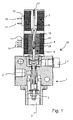
- the valve device (20) shows a valve device (20) with a Proportional control valve (1) of conventional design.
- the proportional control valve (1) has a pressure medium inlet (2), a pressure medium outlet (3) and a vent (4) on.
- the proportional control valve (1) is used for continuous or fine adjustment of a desired Pressure medium flow or a resulting one Pressure at its pressure medium outlet (3) an essentially proportional characteristic.
- the valve device (20) can be used as a pilot valve Actuation of a relay valve (not shown) serve which a brake pressure with a large nominal size controls in a trailer brake system.
- the proportional control valve (1) has a continuously adjustable, longitudinally displaceable plunger (5) mechanically from an electromagnetic device (6) by means of an anchor acting on the plunger (5) (8) can be actuated against a spring force.
- the electromagnetic device (6) next to the armature (8) first magnetic coil device (39) and a second magnetic coil device (43).
- the coil turns of the Magnetic coil devices (39, 43) are on a common Winding core (18), which is essentially concentric is arranged to the anchor (8), wound up.
- the sense of winding is the first and the second magnetic coil device (39, 43) preferably chosen in the same direction.
- the contact pins (14) are the first and the second Magnetic coil device (39, 43) with a not shown electrical connector with other electrical Units connectable.
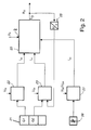
- FIG. 2 schematically shows a preferred arrangement for controlling a valve device (20) according to FIG. 1 in an electrically controlled brake system.
- a brake value transmitter (21) which detects a brake pedal actuation by the driver of a vehicle and is of redundant design for safety reasons, transmits the detected braking request of the driver in the form of two brake value signals (G1, G2) to a first electronic control device (22) and to a second one electronic control device (23).
- the brake value signals (G1, G2) each provide the same information in error-free operation, ie one of the brake value signals (G1, G2) is provided as redundancy.
- the first electronic control device (22) is fed by a first supply voltage (U BI )
- the second electronic control device (23) is fed by a second supply voltage (U BII ), which is independent of the first supply voltage (U BI ) is.
- the first electronic control device (22) delivers a first control current (I 42 ) to the valve device (20).
- the second electronic control device (23) delivers a second control current (I 41 ) to the valve device (20).
- a brake value transmitter (26) is also provided for the parking brake function.
- the latter outputs a parking brake value signal to a third electronic control device (27) for controlling the parking brake function.
- the third electronic control device (27) can be supplied, for example, by the second supply voltage (U BII ), or also by an independent third supply voltage (U BII ) provided for this purpose.
- the third electronic control device (27) outputs a third control current (I 43 ) to the further electromagnetic device (7) of the valve device (20) provided for the parking brake function.
- the valve device (20) is acted upon by an inlet pressure (P III ) at the pressure medium inlet (2).
- a pressure signal (P 22 ) is emitted at the pressure medium outlet (3) to downstream parts of the pressure medium system, in particular to a trailer brake system.
- the pressure signal (P 22 ) emitted is fed back into the second electronic control device (23) via a pressure sensor (25).
- the second electronic control device (23) then carries out a pressure control of the pressure signal (P 22 ) emitted in the sense of a control circuit with the brake value signal (G2) as the desired value.
- 3 shows approximately symbolically the valve device in the middle area (20) with the circuit diagram of a coupled transformer, however for simplicity without the parts for the Parking brake function. To the left are those for following explanation relevant parts of the second electronic control device (23), to the right of it the relevant for the following explanation Parts of the first electronic control device (22).
- the second electronic control device (23) has a microprocessor (30), to which, in addition to the pressure sensor (25) already mentioned, semiconductor switching devices (31, 32, 34, 35) which can be actuated by the microprocessor (30) are connected.
- the first magnetic coil device (39) is connected with its one electrical connection to the switching devices (31, 32) and with its other electrical connection to the switching devices (34, 35) via a resistor (37) used for current detection.
- the switching devices (31, 32, 34, 35) form a full-bridge circuit, with which the magnetic coil device (39) can be connected to the potentials of the second supply voltage (U BII ) and ground in such a way that they can be reversed.
- the switching devices (31, 34) are connected to the second supply voltage (U BII ), the switching devices (32, 35) to the ground potential.
- the control connections of the switching devices (31, 32, 34, 35) are connected to the microprocessor (30).
- the current flow and thus also the magnetic flux in the magnetic coil device (39) can be controlled by clocked actuation of the switching devices (31, 32, 34) via free-wheeling diodes (33, 36) arranged in parallel with the respective switching device (32, 35) connected to the ground potential , 35) are essentially maintained during the breaks.
- By actuating the switching devices (31, 32, 34, 35) in a correspondingly high-frequency manner, an almost continuous current setting of the current (I 41 ) flowing through the magnetic coil device (39) is possible in both directions of current flow.
- the microprocessor (30) can also detect the current flowing through the solenoid coil means (39) current (I 41), and perform in accordance with a control of the current (I 41).
- the parts represented by the control device (22) comprise a microprocessor (40), a semiconductor switching device (41) and a free-wheeling diode (42).
- the switching device (41) is connected on the one hand to the first supply voltage (U BI ) and on the other hand to the second magnetic coil device (43).
- a control connection of the switching device (41) is connected to the microprocessor (40).
- the current (I 42 ) can be applied to the second magnetic coil device (43) as a result of control signals from the microprocessor (40) via the switching device (41).
- the free-wheeling diode (42) in turn serves to maintain the current flow in switching breaks of the switching device (41).
Abstract
Description
Die Erfindung betrifft eine elektromagnetisch betätigbare
Ventileinrichtung gemäß dem Oberbegriff des Patentanspruchs
1 sowie eine Anordnung zur Ansteuerung
einer solchen Ventileinrichtung gemäß dem Patentanspruch
10.The invention relates to an electromagnetically actuated
Valve device according to the preamble of the
Eine gattungsgemäße Ventileinrichtung ist aus der DE 197 17 807 A1 bekannt.A generic valve device is from the DE 197 17 807 A1 known.
Bei der bekannten Ventileinrichtung handelt es sich um ein 4-Wege-Proportionalventil, bei dem ein Steuerschieber von einem ersten Elektromagnet in der einen Richtung und von einem auf der gegenüberliegenden Seite des Steuerschiebers angeordneten zweiten Elektromagnet in die entgegengesetzte Richtung bewegbar ist.The known valve device is a 4-way proportional valve with a control spool from a first electromagnet in one direction and from one on the opposite side of the Control spool arranged second electromagnet in the opposite direction is movable.
In sicherheitskritischen Bereichen der Technik, z. B. in Bremsanlagen für Fahrzeuge, ist es in der Regel erwünscht und erforderlich, Steuer- und Regelkreise mit einer Redundanz zu versehen. So ist es bei herkömmlichen rein druckmittelbetriebenen Bremsanlagen üblich, diese zweikreisig auszuführen, z. B. als Vorderachsund Hinterachs-Bremskreis oder als zwei diagonale Bremskreise. Bei einem Defekt in einem der Bremskreise ist eine Abbremsung des Fahrzeugs dann zumindest noch über den anderen Bremskreis möglich.In safety-critical areas of technology, e.g. B. in braking systems for vehicles, it is usually desirable and required control and regulation circuits with to provide redundancy. So it is with conventional brake systems operated purely by pressure medium, to perform this two-circuit, z. B. as a front axle Rear axle brake circuit or as two diagonal Brake circuits. If there is a defect in one of the brake circuits is then at least a deceleration of the vehicle possible via the other brake circuit.
Bei neueren Bremsanlagen vom elektropneumatischen Typ ist es bekannt, die aus Sicherheitsgründen erforderliche Redundanz dadurch zu erreichen, daß ein rein pneumatischer und ein elektrisch gesteuerter Bremskreis parallel betrieben werden (EP 0 187 901 B1). Hierdurch ist die gesamte Bremsanlage relativ aufwendig, weil neben der elektrischen Steuerung noch ein wesentlicher Teil der bekannten pneumatischen Bremsanlage weiterhin notwendig ist. Zur Verringerung des Aufwands ist es jedoch wünschenswert, auf den rein pneumatisch gesteuerten Teil der Bremsanlage zu verzichten.With newer braking systems of the electropneumatic type it is known to be necessary for security reasons To achieve redundancy in that a purely pneumatic and an electrically controlled brake circuit operated in parallel (EP 0 187 901 B1). hereby the entire brake system is relatively complex because the electrical control is still an essential one Part of the known pneumatic brake system continues necessary is. However, it is to reduce the effort desirable on the purely pneumatically controlled Part of the braking system.
Es ist daher Aufgabe der Erfindung, eine elektromagnetisch betätigbare Ventileinrichtung anzugeben, mittels der eine sicherheitskritische Anlage, insbesondere eine Fahrzeugbremsanlage, bei zumindest gleicher Sicherheit weniger aufwendig gestaltet werden kann.It is therefore an object of the invention to be electromagnetic specify actuatable valve device, by means of which is a safety-critical system, especially one Vehicle brake system, with at least the same level of safety can be designed less complex.
Diese Aufgabe wird durch die in den Patentansprüchen 1
und 10 angegebenen Ausgestaltungen der Erfindung gelöst.
Vorteilhafte Weiterbildungen der Erfindung sind
in den Unteransprüchen angegeben. This object is achieved by the in
Die Erfindung ermöglicht in sehr eleganter Weise die
Realisierung von zwei voneinander getrennten Ansteuerkreisen
für einen Aktuator in einer sicherheitskritischen
Anlage, z. B. einer Bremsanlage. Der Aktuator,
d. h. in einer Bremsanlage ein Bremszylinder, kann dabei
von einer elektromagnetisch betätigbaren Ventileinrichtung
gemäß Patentanspruch 1 mit dem Bremsdruckmedium
beaufschlagt werden. Die Ventileinrichtung ermöglicht
infolge ihrer zwei Magnetspuleneinrichtungen die
Einspeisung zweiter getrennter elektrischer Signale,
die beispielsweise aus getrennten elektrischen Ansteuerkreisen
gewonnen werden können. Infolge der erfindungsgemäßen
Kopplung des magnetischen Flusses der Magnetspuleneinrichtungen
ist ein Betrieb der Ventileinrichtung
auch im Falle eines dauerhaft gestörten elektrischen
Ansteuersignals einer der Magnetspuleneinrichtungen
weiterhin möglich, über die andere Magnetspuleneinrichtung
eine entsprechende Gegenwirkung aufzubringen
und hierdurch den weiteren Betrieb der Bremsanlage
zu ermöglichen. Die erfindungsgemäße Ventileinrichtung
kann besonders vorteilhaft als Vorsteuerventil für ein
Relaisventil in einem Anhängersteuerventil in der
Bremsanlage eines Lastkraftwagens eingesetzt werden.The invention enables the in a very elegant way
Realization of two separate control circuits
for an actuator in a safety-critical
Plant, e.g. B. a brake system. The actuator,
d. H. in a brake system, a brake cylinder can
from an electromagnetically actuated valve device
according to
Gemäß einer vorteilhaften Weiterbildung der Erfindung weisen die erste und die zweite Magnetspuleneinrichtung einen gemeinsamen Anker auf, der zwecks Betätigung mechanisch auf die Ventileinrichtung einwirkt. Durch die Verwendung eines gemeinsamen Ankers kann eine Verbesserung hinsichtlich der Kopplung der magnetischen Flüsse der Magnetspuleneinrichtungen erzielt werden. Außerdem kann hierdurch ein besonders kompakter Aufbau der Ventileinrichtung realisiert werden.According to an advantageous development of the invention have the first and the second magnetic coil device a common anchor on the mechanical for actuation acts on the valve device. Through the Using a common anchor can be an improvement regarding the coupling of the magnetic fluxes of the magnetic coil devices can be achieved. Moreover can thereby a particularly compact structure of the valve device will be realized.
Gemäß einer weiteren vorteilhaften Weiterbildung der Erfindung sind die Spulen der ersten und zweiten Magnetspuleneinrichtung auf einen gemeinsamen Wickelkern gewickelt. Hierdurch kann die Zahl der erforderlichen Bauteile, ebenso wie durch den gemeinsamen Anker, relativ gering gehalten werden.According to a further advantageous development of the Invention are the coils of the first and second magnetic coil devices on a common winding core wound. This can increase the number of required Components, as well as through the common anchor, relative be kept low.
Gemäß einer weiteren vorteilhaften Weiterbildung der Erfindung sind die Magnetspuleneinrichtungen gleichsinnig auf den Wickelkern gewickelt. Hierdurch kann eine bestmögliche Rückwirkungsfreiheit zwischen den Wicklungen erreicht werden.According to a further advantageous development of the Invention, the magnetic coil devices are in the same direction wound on the winding core. As a result, a best possible freedom of interaction between the windings can be achieved.
Gemäß einer vorteilhaften Weiterbildung der Erfindung ist eine dritte Magnetspuleneinrichtung vorgesehen, welche mechanisch oder elektromagnetisch auf den Anker der ersten und/oder der zweiten Magnetspuleneinrichtung einwirkt. Die dritte Magnetspuleneinrichtung kann bei Verwendung der Ventileinrichtungen einer Bremsanlage vorteilhaft für eine Realisierung der Feststellbremsfunktion eingesetzt werden. Gemäß einer vorteilhaften Weiterbildung der Erfindung ist die dritte Magnetspuleneinrichtung als stromlos die Ventileinrichtung betätigender Proportionalmagnet ausgebildet. Hierdurch kann mit der Ventileinrichtung in einfacher Weise die Funktion der Feststellbremse auch bei abgestelltem Fahrzeug, d. h. bei ausgeschalteter Stromversorgungsanlage, aufrechterhalten werden. Hierfür kann die dritte Magnetspuleneinrichtung in vorteilhafter Weise alternativ auch zusammen mit dem ihr zugeordneten Anker als bistabiler Elektromagnet ausgebildet sein.According to an advantageous development of the invention a third magnetic coil device is provided, which mechanically or electromagnetically on the anchor the first and / or the second magnetic coil device acts. The third magnetic coil device can Use of the valve devices of a brake system advantageous for realizing the parking brake function be used. According to an advantageous A further development of the invention is the third magnetic coil device as currentless actuating the valve device Proportional magnet. This can the function with the valve device in a simple manner the parking brake even when the vehicle is parked, d. H. with the power supply switched off, be maintained. The third magnetic coil device can do this alternatively in an advantageous manner also together with the anchor assigned to it as bistable Electromagnet be formed.
Weitere Vorteile der Erfindung, insbesondere auch der erfindungsgemäßen Anordnung zur Ansteuerung einer elektromagnetisch betätigbaren Ventileinrichtung, sind dem nachfolgend anhand von Zeichnungen erläuterten Ausführungsbeispiel zu entnehmen.Further advantages of the invention, in particular the Arrangement according to the invention for controlling an electromagnetic actuatable valve device, are the embodiment explained below with reference to drawings refer to.
Es zeigen
- Fig. 1
- die erfindungsgemäße Ventileinrichtung in einer Anwendung als Anhängersteuerventil und
- Fig. 2
- eine Anordnung zur Ansteuerung der Ventileinrichtung gemäß Fig. 1 und
- Fig. 3
- eine Schaltungsanordnung zur Ansteuerung der Ventileinrichtung gemäß Fig. 1 als Schaltbild.
- Fig. 1
- the valve device according to the invention in an application as a trailer control valve and
- Fig. 2
- an arrangement for controlling the valve device according to FIG. 1 and
- Fig. 3
- a circuit arrangement for controlling the valve device of FIG. 1 as a circuit diagram.
In den Figuren werden gleiche Bezugszeichen für einander entsprechende Bauteile, Signale und sonstige Größen verwendet. In the figures, the same reference numerals are used for one another corresponding components, signals and other sizes used.
Die Fig. 1 zeigt eine Ventileinrichtung (20) mit einem Proportionalsteuerventil (1) üblicher Bauart. Das Proportionalsteuerventil (1) weist einen Druckmitteleinlaß (2), einen Druckmittelauslaß (3) sowie eine Entlüftung (4) auf. Das Proportionalsteuerventil (1) dient zur stufenlosen oder feinstufigen Einstellung einer erwünschten Druckmittelströmung bzw. eines daraus resultierenden Drucks an seinem Druckmittelausgang (3) mit einer im wesentlichen proportionalen Charakteristik. Die Ventileinrichtung (20) kann als Vorsteuerventil zur Ansteuerung eines Relaisventils (nicht dargestellt) dienen, welches einen Bremsdruck mit großer Nennweite in einer Anhängerbremsanlage steuert.1 shows a valve device (20) with a Proportional control valve (1) of conventional design. The proportional control valve (1) has a pressure medium inlet (2), a pressure medium outlet (3) and a vent (4) on. The proportional control valve (1) is used for continuous or fine adjustment of a desired Pressure medium flow or a resulting one Pressure at its pressure medium outlet (3) an essentially proportional characteristic. The valve device (20) can be used as a pilot valve Actuation of a relay valve (not shown) serve which a brake pressure with a large nominal size controls in a trailer brake system.
Hierfür ist das Proportionalsteuerventil (1) über einen kontinuierlich verstellbaren, längsverschiebbaren Stößel (5) mechanisch von einer Elektromagneteinrichtung (6) mittels eines auf den Stößel (5) einwirkenden Ankers (8) gegen eine Federkraft betätigbar. Die Elektromagneteinrichtung (6) weist neben dem Anker (8) eine erste Magnetspuleneinrichtung (39) und eine zweite Magnetspuleneinrichtung (43) auf. Die Spulenwindungen der Magnetspuleneinrichtungen (39, 43) sind auf einen gemeinsamen Wickelkern (18), welcher im wesentlichen konzentrisch zu dem Anker (8) angeordnet ist, aufgewikkelt. Der Wicklungssinn ist bei der ersten und der zweiten Magnetspuleneinrichtung (39, 43) vorzugsweise gleichsinnig gewählt. For this, the proportional control valve (1) has a continuously adjustable, longitudinally displaceable plunger (5) mechanically from an electromagnetic device (6) by means of an anchor acting on the plunger (5) (8) can be actuated against a spring force. The electromagnetic device (6) next to the armature (8) first magnetic coil device (39) and a second magnetic coil device (43). The coil turns of the Magnetic coil devices (39, 43) are on a common Winding core (18), which is essentially concentric is arranged to the anchor (8), wound up. The sense of winding is the first and the second magnetic coil device (39, 43) preferably chosen in the same direction.
Über einen elektrischen Steckkontakt (11), enthaltend die Kontaktstifte (14), sind die erste und die zweite Magnetspuleneinrichtung (39, 43) mit einem nicht dargestellten elektrischen Steckverbinder mit anderen elektrischen Einheiten verbindbar.Containing an electrical plug contact (11) the contact pins (14) are the first and the second Magnetic coil device (39, 43) with a not shown electrical connector with other electrical Units connectable.
Über eine auf die Elektromagneteinrichtung (6) aufgesetzte weitere Elektromagneteinrichtung (7) kann eine Feststellbrems-Funktion mit der beschriebenen Ventileinrichtung (20) realisiert werden. Die weitere Elektromagneteinrichtung (7) weist einen Anker (9) auf, dessen Mittelachse im wesentlichen mit der Mittelachse des Ankers (8) fluchtet, wobei der Anker (9) auf den Anker (8) mechanisch einwirkt. Der Anker (9) ist durch eine Feder (10) in Richtung zu dem Anker (8) vorgespannt. Durch Betätigung der weiteren Elektromagneteinrichtung (7) über elektrische Signale, die über einen die Kontaktstifte (16, 17) aufweisenden elektrischen Anschluß (15) an eine Spule der weiteren Elektromagneteinrichtung (7) geführt werden können, kann der Anker (9) entgegen der Kraft der Feder (10) bewegt werden. Hierdurch wird die von der Feder (10) über den Anker (9) auf den Anker (8) ausgeübte Kraft eliminiert, so daß der Anker (8) unbeeinflußt von der weiteren Elektromagneteinrichtung (7) betätigbar ist.Via one placed on the electromagnetic device (6) further electromagnetic device (7) can Parking brake function with the valve device described (20) can be realized. The further electromagnetic device (7) has an anchor (9), its central axis essentially with the central axis of the armature (8) is aligned, the armature (9) on the Anchor (8) acts mechanically. The anchor (9) is through a spring (10) is biased towards the armature (8). By actuating the further electromagnetic device (7) about electrical signals coming through a the electrical contact pins (16, 17) Connection (15) to a coil of the further electromagnetic device (7) can be guided, the anchor (9) against the force of the spring (10) are moved. This causes the spring (10) to move over the armature (9) force exerted on the armature (8), so that the armature (8) is unaffected by the further electromagnetic device (7) can be actuated.
In der Fig. 2 ist eine bevorzugte Anordnung zur Ansteuerung einer Ventileinrichtung (20) gemäß Fig. 1 in einer elektrisch gesteuerten Bremsanlage schematisch dargestellt. Ein eine Bremspedalbetätigung durch den Fahrer eines Fahrzeugs erfassender Bremswertgeber (21), welcher aus Sicherheitsgründen zweikreisig redundant ausgebildet ist, gibt den erfaßten Bremswunsch des Fahrers in Form von zwei Bremswertsignalen (G1, G2) an eine erste elektronische Steuereinrichtung (22) sowie an eine zweite elektronische Steuereinrichtung (23) ab. Die Bremswertsignale (G1, G2) geben im fehlerfreien Betrieb jeweils die gleiche Information ab, d.h. eines der Bremswertsignale (G1, G2) ist als Redundanz vorgesehen. Die erste elektronische Steuereinrichtung (22) wird aus Gründen der Zweikreisigkeit von einer ersten Versorgungsspannung (UBI) gespeist, die zweite elektronische Steuereinrichtung (23) wird von einer zweiten Versorgungsspannung (UBII) gespeist, welche von der ersten Versorgungsspannug (UBI) unabhängig ist.FIG. 2 schematically shows a preferred arrangement for controlling a valve device (20) according to FIG. 1 in an electrically controlled brake system. A brake value transmitter (21), which detects a brake pedal actuation by the driver of a vehicle and is of redundant design for safety reasons, transmits the detected braking request of the driver in the form of two brake value signals (G1, G2) to a first electronic control device (22) and to a second one electronic control device (23). The brake value signals (G1, G2) each provide the same information in error-free operation, ie one of the brake value signals (G1, G2) is provided as redundancy. For reasons of dual circuitry, the first electronic control device (22) is fed by a first supply voltage (U BI ), the second electronic control device (23) is fed by a second supply voltage (U BII ), which is independent of the first supply voltage (U BI ) is.
Die erste elektronische Steuereinrichtung (22) gibt einen ersten Steuerstrom (I42) an die Ventileinrichtung (20) ab. Die zweite elektronische Steuereinrichtung (23) gibt einen zweiten Steuerstrom (I41) an die Ventileinrichtung (20) ab. Des weiteren ist ein Bremswertgeber (26) für die Feststell-Bremsfunktion vorgesehen. Dieser gibt ein Feststell-Bremswertsignal an eine dritte elektronische Steuereinrichtung (27) zur Steuerung der Feststell-Bremsfunktion ab. Die dritte elektronische Steuereinrichtung (27) kann beispielsweise von der zweiten Versorgungsspannung (UBII) versorgt werden, oder auch von einer hierfür eigens vorgesehenen, unabhängigen dritten Versorgungsspannung (UBII). Die dritte elektronische Steuereinrichtung (27) gibt einen dritten Steuerstrom (I43) an die für die Feststell-Bremsfunktion vorgesehene weitere Elektromagneteinrichtung (7) der Ventileinrichtung (20) ab.The first electronic control device (22) delivers a first control current (I 42 ) to the valve device (20). The second electronic control device (23) delivers a second control current (I 41 ) to the valve device (20). A brake value transmitter (26) is also provided for the parking brake function. The latter outputs a parking brake value signal to a third electronic control device (27) for controlling the parking brake function. The third electronic control device (27) can be supplied, for example, by the second supply voltage (U BII ), or also by an independent third supply voltage (U BII ) provided for this purpose. The third electronic control device (27) outputs a third control current (I 43 ) to the further electromagnetic device (7) of the valve device (20) provided for the parking brake function.
Die Ventileinrichtung (20) wird am Druckmitteleinlaß (2) mit einem Eingangsdruck (PIII) beaufschlagt. Ausgangsseitig wird am Druckmittelauslaß (3) ein Drucksignal (P22) an nachgeschaltete Teile der Druckmittelanlage, insbesondere an eine Anhängerbremsanlage, abgegeben. Über einen Drucksensor (25) wird das abgegebene Drucksignal (P22) in die zweite elektronische Steuereinrichtung (23) rückgekoppelt. Die zweite elektronische Steuereinrichtung (23) führt dann eine Druckregelung des abgegebenen Drucksignals (P22) im Sinne eines Regelkreises mit dem Bremswertsignal (G2) als Sollwert aus.The valve device (20) is acted upon by an inlet pressure (P III ) at the pressure medium inlet (2). On the output side, a pressure signal (P 22 ) is emitted at the pressure medium outlet (3) to downstream parts of the pressure medium system, in particular to a trailer brake system. The pressure signal (P 22 ) emitted is fed back into the second electronic control device (23) via a pressure sensor (25). The second electronic control device (23) then carries out a pressure control of the pressure signal (P 22 ) emitted in the sense of a control circuit with the brake value signal (G2) as the desired value.
Die nähere schaltungstechnische Ausgestaltung der anhand der Fig. 2 schematisch dargestellten, für die Ansteuerung der Ventileinrichtung (20) relevanten Teile der Steuereinrichtungen (22, 23) soll nachfolgend anhand der Fig. 3 erläutert werden. Die Fig. 3 zeigt etwa im mittleren Bereich symbolisch die Ventileinrichtung (20) mit dem Schaltbild eines mitgekoppelten Transformators, jedoch zur Vereinfachung ohne die Teile für die Feststell-Bremsfunktion. Links davon sind die für die nachfolgende Erläuterung relevanten Teile der zweiten elektronischen Steuereinrichtung (23) dargestellt, rechts davon die für die nachfolgende Erläuterung relevanten Teile der ersten elektronischen Steuereinrichtung (22).The closer circuitry design of the 2 schematically shown for the control the valve device (20) relevant parts of the control devices (22, 23) is to be based on 3 are explained. 3 shows approximately symbolically the valve device in the middle area (20) with the circuit diagram of a coupled transformer, however for simplicity without the parts for the Parking brake function. To the left are those for following explanation relevant parts of the second electronic control device (23), to the right of it the relevant for the following explanation Parts of the first electronic control device (22).
Die zweite elektronische Steuereinrichtung (23) weist einen Mikroprozessor (30) auf, an dem neben dem bereits erwähnten Drucksensor (25) noch von dem Mikroprozessor (30) betätigbare Halbleiter-Schalteinrichtungen (31, 32, 34, 35) angeschlossen sind. Die erste Magnetspuleneinrichtung (39) ist mit ihrem einen elektrischen Anschluß mit den Schalteinrichtungen (31, 32) verbunden, mit ihrem anderen elektrischen Anschluß über einen zur Stromerfassung dienenden Widerstand (37) mit den Schalteinrichtungen (34, 35) verbunden. Die Schalteinrichtungen (31, 32, 34, 35) bilden eine Vollbrückenschaltung, mit der die Magnetspuleneinrichtung (39) umpolbar mit den Potentialen der zweiten Versorgungsspannung (UBII) und Masse verbindbar ist. Hierfür sind die Schalteinrichtungen (31, 34) mit der zweiten Versorgungsspannung (UBII) verbunden, die Schalteinrichtungen (32, 35) mit dem Masse-Potential. Die Steueranschlüsse der Schalteinrichtungen (31, 32, 34, 35) sind mit dem Mikroprozessor (30) verbunden.The second electronic control device (23) has a microprocessor (30), to which, in addition to the pressure sensor (25) already mentioned, semiconductor switching devices (31, 32, 34, 35) which can be actuated by the microprocessor (30) are connected. The first magnetic coil device (39) is connected with its one electrical connection to the switching devices (31, 32) and with its other electrical connection to the switching devices (34, 35) via a resistor (37) used for current detection. The switching devices (31, 32, 34, 35) form a full-bridge circuit, with which the magnetic coil device (39) can be connected to the potentials of the second supply voltage (U BII ) and ground in such a way that they can be reversed. For this purpose, the switching devices (31, 34) are connected to the second supply voltage (U BII ), the switching devices (32, 35) to the ground potential. The control connections of the switching devices (31, 32, 34, 35) are connected to the microprocessor (30).
Über parallel zu der jeweiligen mit dem Masse-Potential verbundenen Schalteinrichtung (32, 35) angeordnete Freilaufdioden (33, 36) kann der Stromfluß und hiermit auch der magnetische Fluß in der Magnetspuleneinrichtung (39) bei getakteter Betätigung der Schalteinrichtungen (31, 32, 34, 35) während der Schaltpausen im wesentlichen aufrechterhalten werden. Durch entsprechend hochfrequent getaktete Betätigungen der Schalteinrichtungen (31, 32, 34, 35) ist damit eine nahezu kontinuierliche Stromeinstellung des durch die Magnetspuleneinrichtung (39) fließenden Stroms (I41) in beiden Stromflußrichtungen möglich.The current flow and thus also the magnetic flux in the magnetic coil device (39) can be controlled by clocked actuation of the switching devices (31, 32, 34) via free-wheeling diodes (33, 36) arranged in parallel with the respective switching device (32, 35) connected to the ground potential , 35) are essentially maintained during the breaks. By actuating the switching devices (31, 32, 34, 35) in a correspondingly high-frequency manner, an almost continuous current setting of the current (I 41 ) flowing through the magnetic coil device (39) is possible in both directions of current flow.
Mittels des zur Stromerfassung dienenden Widerstands (37) und einer nachgeschalteten Verstärkereinrichtung (38) kann der Mikroprozessor (30) zudem den durch die Magnetspuleneinrichtung (39) fließenden Strom (I41) erfassen und entsprechend eine Regelung des Stroms (I41) durchführen.By means of the serving for the current detection resistor (37) and a downstream amplifier means (38) of the microprocessor (30) can also detect the current flowing through the solenoid coil means (39) current (I 41), and perform in accordance with a control of the current (I 41).
Die von dem Steuergerät (22) dargestellten Teile umfassen einen Mikroprozessor (40), eine Halbleiter-Schalteinrichtung (41) sowie eine Freilaufdiode (42). Die Schalteinrichtung (41) ist einerseits mit der ersten Versorgungsspannung (UBI) verbunden, andererseits mit der zweiten Magnetspuleneinrichtung (43). Ein Steueranschluß der Schalteinrichtung (41) ist mit dem Mikroprozessor (40) verbunden. Über die Schalteinrichtung (41) ist die zweite Magnetspuleneinrichtung (43) infolge von Steuersignalen durch den Mikroprozessor (40) mit dem Strom (I42) beaufschlagbar. Die Freilaufdiode (42) dient wiederum zur Aufrechterhaltung des Stromflusses in Schaltpausen der Schalteinrichtung (41).The parts represented by the control device (22) comprise a microprocessor (40), a semiconductor switching device (41) and a free-wheeling diode (42). The switching device (41) is connected on the one hand to the first supply voltage (U BI ) and on the other hand to the second magnetic coil device (43). A control connection of the switching device (41) is connected to the microprocessor (40). The current (I 42 ) can be applied to the second magnetic coil device (43) as a result of control signals from the microprocessor (40) via the switching device (41). The free-wheeling diode (42) in turn serves to maintain the current flow in switching breaks of the switching device (41).
Claims (13)
Applications Claiming Priority (2)
| Application Number | Priority Date | Filing Date | Title |
|---|---|---|---|
| DE10204553 | 2002-02-05 | ||
| DE10204553A DE10204553A1 (en) | 2002-02-05 | 2002-02-05 | Electromagnetically actuated valve device and arrangement for controlling such a valve device |
Publications (2)
| Publication Number | Publication Date |
|---|---|
| EP1332938A2 true EP1332938A2 (en) | 2003-08-06 |
| EP1332938A3 EP1332938A3 (en) | 2004-03-17 |
Family
ID=7713675
Family Applications (1)
| Application Number | Title | Priority Date | Filing Date |
|---|---|---|---|
| EP02026734A Withdrawn EP1332938A3 (en) | 2002-02-05 | 2002-11-30 | Electromagnetically actuatable valve device as well as an arrangement for driving such a valve device |
Country Status (2)
| Country | Link |
|---|---|
| EP (1) | EP1332938A3 (en) |
| DE (1) | DE10204553A1 (en) |
Cited By (2)
| Publication number | Priority date | Publication date | Assignee | Title |
|---|---|---|---|---|
| WO2019068501A1 (en) * | 2017-10-06 | 2019-04-11 | Continental Teves Ag & Co. Ohg | Valve arrangement and brake system |
| WO2020060180A1 (en) * | 2018-09-19 | 2020-03-26 | 주식회사 만도 | Brake device and method for controlling same |
Families Citing this family (2)
| Publication number | Priority date | Publication date | Assignee | Title |
|---|---|---|---|---|
| DE102006047440A1 (en) * | 2006-10-07 | 2008-04-10 | Continental Teves Ag & Co. Ohg | Electromagnetic valve e.g. two way seat valve, for slip-regulated motor vehicle brake system, has solenoid coil arranged coaxial to armature, and magnetic coil with wound coil for actuating valve closing unit in intermediate position |
| DE102016208966A1 (en) * | 2016-05-24 | 2017-11-30 | Robert Bosch Gmbh | Electronically pressure-controllable vehicle brake system and method for controlling an electronically pressure-controllable vehicle brake system |
Citations (10)
| Publication number | Priority date | Publication date | Assignee | Title |
|---|---|---|---|---|
| US2983285A (en) * | 1959-06-05 | 1961-05-09 | Lawrence H Gardner | Solenoid operated valve |
| DE1775713A1 (en) * | 1968-09-13 | 1971-08-12 | Herion Werke Kg | Solenoid valve |
| JPS5576746A (en) * | 1978-12-06 | 1980-06-10 | Keihin Seiki Mfg Co Ltd | Braking device for automobile |
| DE3241521A1 (en) * | 1982-11-10 | 1984-05-10 | Robert Bosch Gmbh, 7000 Stuttgart | Proportional magnet |
| EP0205928A1 (en) * | 1985-06-14 | 1986-12-30 | Knorr-Bremse Ag | Circuit arrangement for the detection of a conduit rupture in an electro-pneumatical vehicle brake system, with a trailer brake controlled by the traction vehicle |
| EP0288034A2 (en) * | 1987-04-23 | 1988-10-26 | The Boeing Company | Flight control system employing three controllers operating a dual actuator |
| DE3913860A1 (en) * | 1989-04-27 | 1990-10-31 | Bosch Gmbh Robert | Pressure medium vehicle braking system with braking valve transmitter - delivers braking signal to evaluation unit where it is converted for control of switch magnet |
| DE4310960A1 (en) * | 1992-04-06 | 1993-10-07 | Fasco Controls | Improved three-way and three-position solenoid valve |
| WO1997032137A1 (en) * | 1996-03-01 | 1997-09-04 | Robert Bosch Gmbh | Electromagnetically operated directional valve |
| DE19717807A1 (en) * | 1997-04-26 | 1998-10-29 | Rexroth Mannesmann Gmbh | Distributing valve, especially four-way proportional valve |
Family Cites Families (2)
| Publication number | Priority date | Publication date | Assignee | Title |
|---|---|---|---|---|
| DE3527174A1 (en) * | 1985-07-30 | 1987-02-12 | Bosch Gmbh Robert | DOUBLE ACTING SOLENOID VALVE |
| JP2001003770A (en) * | 1999-06-16 | 2001-01-09 | Unisia Jecs Corp | Motor-driven throttle valve device |
-
2002
- 2002-02-05 DE DE10204553A patent/DE10204553A1/en not_active Withdrawn
- 2002-11-30 EP EP02026734A patent/EP1332938A3/en not_active Withdrawn
Patent Citations (10)
| Publication number | Priority date | Publication date | Assignee | Title |
|---|---|---|---|---|
| US2983285A (en) * | 1959-06-05 | 1961-05-09 | Lawrence H Gardner | Solenoid operated valve |
| DE1775713A1 (en) * | 1968-09-13 | 1971-08-12 | Herion Werke Kg | Solenoid valve |
| JPS5576746A (en) * | 1978-12-06 | 1980-06-10 | Keihin Seiki Mfg Co Ltd | Braking device for automobile |
| DE3241521A1 (en) * | 1982-11-10 | 1984-05-10 | Robert Bosch Gmbh, 7000 Stuttgart | Proportional magnet |
| EP0205928A1 (en) * | 1985-06-14 | 1986-12-30 | Knorr-Bremse Ag | Circuit arrangement for the detection of a conduit rupture in an electro-pneumatical vehicle brake system, with a trailer brake controlled by the traction vehicle |
| EP0288034A2 (en) * | 1987-04-23 | 1988-10-26 | The Boeing Company | Flight control system employing three controllers operating a dual actuator |
| DE3913860A1 (en) * | 1989-04-27 | 1990-10-31 | Bosch Gmbh Robert | Pressure medium vehicle braking system with braking valve transmitter - delivers braking signal to evaluation unit where it is converted for control of switch magnet |
| DE4310960A1 (en) * | 1992-04-06 | 1993-10-07 | Fasco Controls | Improved three-way and three-position solenoid valve |
| WO1997032137A1 (en) * | 1996-03-01 | 1997-09-04 | Robert Bosch Gmbh | Electromagnetically operated directional valve |
| DE19717807A1 (en) * | 1997-04-26 | 1998-10-29 | Rexroth Mannesmann Gmbh | Distributing valve, especially four-way proportional valve |
Non-Patent Citations (1)
| Title |
|---|
| PATENT ABSTRACTS OF JAPAN vol. 004, no. 120 (M-028), 26. August 1980 (1980-08-26) -& JP 55 076746 A (KEIHIN SEIKI MFG CO LTD), 10. Juni 1980 (1980-06-10) * |
Cited By (5)
| Publication number | Priority date | Publication date | Assignee | Title |
|---|---|---|---|---|
| WO2019068501A1 (en) * | 2017-10-06 | 2019-04-11 | Continental Teves Ag & Co. Ohg | Valve arrangement and brake system |
| CN111183076A (en) * | 2017-10-06 | 2020-05-19 | 大陆-特韦斯贸易合伙股份公司及两合公司 | Valve device and brake system |
| CN111183076B (en) * | 2017-10-06 | 2022-06-07 | 大陆-特韦斯贸易合伙股份公司及两合公司 | Valve device and brake system |
| US11685356B2 (en) | 2017-10-06 | 2023-06-27 | Continental Teves Ag & Co. Ohg | Valve arrangement and brake system |
| WO2020060180A1 (en) * | 2018-09-19 | 2020-03-26 | 주식회사 만도 | Brake device and method for controlling same |
Also Published As
| Publication number | Publication date |
|---|---|
| DE10204553A1 (en) | 2003-08-14 |
| EP1332938A3 (en) | 2004-03-17 |
Similar Documents
| Publication | Publication Date | Title |
|---|---|---|
| EP3536570B1 (en) | Braking assembly for a vehicle train and machine equipped with same | |
| EP2059427B1 (en) | Valve unit, electro-pneumatic brake control device having a valve unit of said type for controlling a parking brake, vehicle brake system having a brake control device of said type and vehicle having a brake system of said type | |
| EP2059426B1 (en) | Valve unit, brake control device, vehicle brake system and vehicle | |
| EP1687159B2 (en) | Valve device for a pneumatic suspension unit of a vehicle | |
| EP0964806B1 (en) | Electrically controlled braking system for a wheeled vehicle | |
| EP1132274B1 (en) | Brake Pressure Modulator for electronic braking system | |
| EP2059429A1 (en) | Valve unit for an electro-pneumatic brake control device | |
| DE102016208966A1 (en) | Electronically pressure-controllable vehicle brake system and method for controlling an electronically pressure-controllable vehicle brake system | |
| EP0207275A2 (en) | Assisting and locking brake for utility vehicles | |
| EP3257060B1 (en) | Solenoid valve, valve device with a solenoid valve of this type, vehicle with such a valve and method for operating a solenoid valve of this type | |
| DE10020419A1 (en) | Brake control system has isolating valve to control level of pump outlet pressure delivered to driven wheels during automatic operation of brake system, and has spool interacting with stepped bore and to form fluid damping mechanism | |
| EP3691940A1 (en) | Valve arrangement and brake system | |
| EP1332938A2 (en) | Electromagnetically actuatable valve device as well as an arrangement for driving such a valve device | |
| EP0363615B1 (en) | Compressed-air brake system | |
| DE19510716C2 (en) | Emergency stop and / or handbrake device for industrial trucks | |
| DE3506419C1 (en) | Pressure brake system for vehicles with an electric brake control system | |
| DE3439067A1 (en) | Arrangement for the locking of a pressure medium-actuated wheel brake | |
| DE10245916A1 (en) | Brake force modulation system for use with pneumatically-operated brakes, has three electronically-controlled magnetic valves in air line leading from pressure supply to brakes | |
| WO2022156864A1 (en) | Electrohydraulic brake control device for a motor vehicle, braking system comprising such a brake control device, and method for operating a brake control device | |
| DE19715024B4 (en) | Circuit arrangement for connecting electrical consumers to the power supply | |
| DE2534879B2 (en) | Dual circuit brake arrangement | |
| DE10315040A1 (en) | Brake control unit with a solenoid valve | |
| WO2024027924A1 (en) | Electromechanical brake system with pneumatic actuation of the trailer | |
| DE102021102058A1 (en) | Pedal emulator for a vehicle | |
| WO2023001472A1 (en) | Electropneumatic parking brake unit with an emergency release |
Legal Events
| Date | Code | Title | Description |
|---|---|---|---|
| PUAI | Public reference made under article 153(3) epc to a published international application that has entered the european phase |
Free format text: ORIGINAL CODE: 0009012 |
|
| AK | Designated contracting states |
Designated state(s): AT BE BG CH CY CZ DE DK EE ES FI FR GB GR IE IT LI LU MC NL PT SE SK TR |
|
| AX | Request for extension of the european patent |
Extension state: AL LT LV MK RO SI |
|
| PUAL | Search report despatched |
Free format text: ORIGINAL CODE: 0009013 |
|
| AK | Designated contracting states |
Kind code of ref document: A3 Designated state(s): AT BE BG CH CY CZ DE DK EE ES FI FR GB GR IE IT LI LU MC NL PT SE SK TR |
|
| AX | Request for extension of the european patent |
Extension state: AL LT LV MK RO SI |
|
| 17P | Request for examination filed |
Effective date: 20040917 |
|
| AKX | Designation fees paid |
Designated state(s): DE IT NL SE |
|
| 17Q | First examination report despatched |
Effective date: 20050103 |
|
| STAA | Information on the status of an ep patent application or granted ep patent |
Free format text: STATUS: THE APPLICATION HAS BEEN WITHDRAWN |
|
| 18W | Application withdrawn |
Effective date: 20050420 |