EP1332672A1 - Reel unit for spinning reel - Google Patents
Reel unit for spinning reel Download PDFInfo
- Publication number
- EP1332672A1 EP1332672A1 EP03394005A EP03394005A EP1332672A1 EP 1332672 A1 EP1332672 A1 EP 1332672A1 EP 03394005 A EP03394005 A EP 03394005A EP 03394005 A EP03394005 A EP 03394005A EP 1332672 A1 EP1332672 A1 EP 1332672A1
- Authority
- EP
- European Patent Office
- Prior art keywords
- casing
- reel unit
- reel
- rotor
- cover
- Prior art date
- Legal status (The legal status is an assumption and is not a legal conclusion. Google has not performed a legal analysis and makes no representation as to the accuracy of the status listed.)
- Granted
Links
- 238000009987 spinning Methods 0.000 title claims abstract description 41
- 230000007246 mechanism Effects 0.000 claims abstract description 31
- 229920003002 synthetic resin Polymers 0.000 claims description 14
- 239000000057 synthetic resin Substances 0.000 claims description 14
- 229910052751 metal Inorganic materials 0.000 claims description 7
- 239000002184 metal Substances 0.000 claims description 7
- 238000004804 winding Methods 0.000 claims description 4
- 230000003014 reinforcing effect Effects 0.000 claims description 3
- 238000000465 moulding Methods 0.000 description 10
- 229910000838 Al alloy Inorganic materials 0.000 description 9
- 230000002265 prevention Effects 0.000 description 5
- 239000013585 weight reducing agent Substances 0.000 description 4
- 230000002093 peripheral effect Effects 0.000 description 3
- 230000008859 change Effects 0.000 description 2
- 239000003365 glass fiber Substances 0.000 description 2
- 238000001746 injection moulding Methods 0.000 description 2
- 239000007788 liquid Substances 0.000 description 2
- 230000001050 lubricating effect Effects 0.000 description 2
- 229920002647 polyamide Polymers 0.000 description 2
- 230000001681 protective effect Effects 0.000 description 2
- 238000005406 washing Methods 0.000 description 2
- XLYOFNOQVPJJNP-UHFFFAOYSA-N water Substances O XLYOFNOQVPJJNP-UHFFFAOYSA-N 0.000 description 2
- RTAQQCXQSZGOHL-UHFFFAOYSA-N Titanium Chemical compound [Ti] RTAQQCXQSZGOHL-UHFFFAOYSA-N 0.000 description 1
- 229920000122 acrylonitrile butadiene styrene Polymers 0.000 description 1
- 229910045601 alloy Inorganic materials 0.000 description 1
- 239000000956 alloy Substances 0.000 description 1
- 229910052782 aluminium Inorganic materials 0.000 description 1
- XAGFODPZIPBFFR-UHFFFAOYSA-N aluminium Chemical compound [Al] XAGFODPZIPBFFR-UHFFFAOYSA-N 0.000 description 1
- 230000008602 contraction Effects 0.000 description 1
- 230000002950 deficient Effects 0.000 description 1
- 239000012530 fluid Substances 0.000 description 1
- 238000004519 manufacturing process Methods 0.000 description 1
- 150000002739 metals Chemical class 0.000 description 1
- 230000004048 modification Effects 0.000 description 1
- 238000012986 modification Methods 0.000 description 1
- 230000010355 oscillation Effects 0.000 description 1
- 230000009467 reduction Effects 0.000 description 1
- 229920005989 resin Polymers 0.000 description 1
- 239000011347 resin Substances 0.000 description 1
- 239000007787 solid Substances 0.000 description 1
- 239000010936 titanium Substances 0.000 description 1
- 229910052719 titanium Inorganic materials 0.000 description 1
- -1 titanium or the like Chemical class 0.000 description 1
Images




Classifications
-
- A—HUMAN NECESSITIES
- A01—AGRICULTURE; FORESTRY; ANIMAL HUSBANDRY; HUNTING; TRAPPING; FISHING
- A01K—ANIMAL HUSBANDRY; AVICULTURE; APICULTURE; PISCICULTURE; FISHING; REARING OR BREEDING ANIMALS, NOT OTHERWISE PROVIDED FOR; NEW BREEDS OF ANIMALS
- A01K89/00—Reels
- A01K89/01—Reels with pick-up, i.e. with the guiding member rotating and the spool not rotating during normal retrieval of the line
- A01K89/01121—Frame details
- A01K89/01123—Frame disassembly features
-
- A—HUMAN NECESSITIES
- A01—AGRICULTURE; FORESTRY; ANIMAL HUSBANDRY; HUNTING; TRAPPING; FISHING
- A01K—ANIMAL HUSBANDRY; AVICULTURE; APICULTURE; PISCICULTURE; FISHING; REARING OR BREEDING ANIMALS, NOT OTHERWISE PROVIDED FOR; NEW BREEDS OF ANIMALS
- A01K89/00—Reels
- A01K89/015—Reels with a rotary drum, i.e. with a rotating spool
-
- A—HUMAN NECESSITIES
- A01—AGRICULTURE; FORESTRY; ANIMAL HUSBANDRY; HUNTING; TRAPPING; FISHING
- A01K—ANIMAL HUSBANDRY; AVICULTURE; APICULTURE; PISCICULTURE; FISHING; REARING OR BREEDING ANIMALS, NOT OTHERWISE PROVIDED FOR; NEW BREEDS OF ANIMALS
- A01K89/00—Reels
- A01K89/01—Reels with pick-up, i.e. with the guiding member rotating and the spool not rotating during normal retrieval of the line
-
- A—HUMAN NECESSITIES
- A01—AGRICULTURE; FORESTRY; ANIMAL HUSBANDRY; HUNTING; TRAPPING; FISHING
- A01K—ANIMAL HUSBANDRY; AVICULTURE; APICULTURE; PISCICULTURE; FISHING; REARING OR BREEDING ANIMALS, NOT OTHERWISE PROVIDED FOR; NEW BREEDS OF ANIMALS
- A01K89/00—Reels
- A01K89/01—Reels with pick-up, i.e. with the guiding member rotating and the spool not rotating during normal retrieval of the line
- A01K89/01121—Frame details
- A01K89/01127—Reel supports
Definitions
- This invention generally relates to reel units. More specifically, the present invention relates to reel units for spinning reels mounted to a fishing rod that winds fishing line onto its spool with a rotor that rotates in cooperation with rotation of a handle.
- spinning reels have a reel unit, a rotor rotatably supported by the reel unit, and a spool that is arranged in front of the rotor and on the outer periphery of which fishing line is wound by the rotor.
- the reel unit has a handle for rotating the rotor.
- a reel unit generally has a casing and a mounting leg portion that are formed unitarily from an injection-molded synthetic resin or die-cast aluminum, and a cover portion.
- the casing accommodates a drive portion and has an opening for mounting the drive portion.
- the mounting leg portion has a leg portion extending upward from the casing and a fishing rod-mounting portion extending frontward and rearward from the tip of the leg portion.
- the cover portion is provided for covering the opening of the casing.
- the rotor is supported rotatably by the casing and is driven to rotate by a drive mechanism provided therein.
- the spool is supported by the casing so that it can shift back and forth, and an oscillating mechanism is provided therein to shift the spool back and forth.
- the rotation shaft of the handle is supported rotatably by the casing and the cover portion.
- This type of spinning reel is required to be lightweight and be formed with a high degree of precision.
- reduced weight and a high degree precision can be achieved when the wall thickness is reduced to reduce sink marks during the molding.
- the mounting leg portion needs to have a large wall thickness to maintain the relative strength.
- the casing and the mounting leg portion are formed unitarily, and therefore, the casing is stretched by the thick-walled mounting leg portion during the molding. As a result, variation in thickness is caused in the thin-walled casing if the wall thickness of the casing is reduced to attain weight reduction and increased precision.
- a reel unit for a spinning reel having a lid portion in which the cover portion and the mounting leg portion are formed unitarily is disclosed in Japanese Unexamined Patent Publication No. 10-004836.
- the casing By providing the casing separately, it is possible to reduce the wall thickness of the casing and maintain a high degree of precision.
- the mounting leg portion unitarily with the cover portion, which does not need to be formed with so high a degree of precision, it is possible to reduce the wall thickness of the mounting leg portion and to maintain the relative strength of the mounting leg portion.
- the lid portion formed unitarily with the mounting leg portion is made of metal, which has a high relative strength, to maintain a high degree of precision and relative strength.
- metal which has a high relative strength, to maintain a high degree of precision and relative strength.
- a lid portion made of metal if reduction in weight is desired while maintaining a high degree of precision and relative strength, it is necessary to use expensive metals such as titanium or the like, increasing the manufacturing cost.
- a purpose of the present invention is to provide a reel unit for a spinning reel having a lid portion in which a cover portion and a mounting leg portion are formed unitarily, in which the weight of the lid portion is reduced at low cost while maintaining a high degree of precision and relative strength.
- a reel unit for a spinning reel is a reel unit for a spinning reel, which is mounted to a fishing rod and is for winding fishing line onto a spool by a rotor that rotates in cooperation with rotation of a handle.
- the reel unit comprises a casing, a lid portion, and a wall portion.
- the casing includes an opening formed at its side, a mechanism accommodating space formed therein, and a rotation support portion for supporting a rotation shaft of the rotor, the rotation support portion formed so as to be arranged inside a circular hollow formed at the reel unit side of the rotor.
- the lid portion has a cover portion and a mounting leg portion, the cover portion detachably fixed to the casing, covering the opening of the casing, and formed unitarily with a wall portion formed at its side to which the rotor is mounted so that a space is formed inside, and the mounting leg portion extending from the cover portion and having a front end to which the fishing rod can be attached.
- the cover portion is formed unitarily with the mounting leg portion for mounting a fishing rod, and the wall portion is formed at the side of the cover portion to which the rotor is mounted that is formed so as to cover the opening.
- the wall portion is formed unitarily at the side to which the rotor is mounted in addition to the portion covering the opening, and consequently, the entire cover portion has a box-like shape enclosing a space therein. Therefore, stress is distributed and the relative strength of the cover portion is increased. Moreover, because stress is distributed, deformations do not occur easily during the molding and a high degree of precision can be maintained.
- the lid portion including the cover portion is made of a synthetic resin or an aluminum alloy, which has a low relative strength, it is possible to maintain a high degree of precision and relative strength. Furthermore, if the lid portion including the cover portion is made of an aluminum alloy or a synthetic resin, the weight of the lid portion can be reduced at low cost.
- a circular flange portion having a first flange portion and a second flange portion, the first flange portion arranged on substantially the same plane as the end face of the hollow and provided at the casing, and the second flange portion provided at the wall portion such that the first and second flange portions cover the hollow.
- the flange portion can prevent foreign matter such as water or liquids from entering the hollow.
- the second flange portion is formed unitarily the wall portion.
- the second flange portion and the wall portion are formed unitarily, it is possible to increase the relative strength of the cover portion by providing the second flange portion.
- the second flange portion can be provided separately from the wall portion. In this case, washing and lubricating the inside of the hollow of the rotor can be carried out easily since only the second flange portion needs to be detached.
- the first flange portion is formed unitarily with the casing.
- the casing and the first flange portion are formed unitarily, the relative strength of the casing is high.
- the first flange portion can be provided separately from the casing. In this case, washing and lubricating the inside of the hollow of the rotor can be easily carried out since only the first flange portion needs to be detached.
- the casing and the lid portion are made of a synthetic resin.
- the weight of the lid portion can be reduced while a high degree of precision and strength are maintained, and at the same time, the cost of the casing can be reduced since the casing is made of a synthetic resin.
- the casing and the lid portion can be made of a light weight metal such as aluminum alloy.
- the cover portion has a trimmed portion formed continuously with the second flange portion and formed on the circumference facing the opening. In this case, the relative strength is further increased with the trimmed portion.
- the lid portion has a handle support portion for supporting the handle.
- the need for providing a protrusion for supporting a shaft is eliminated since the cover portion only needs to serve the function of mere covering.
- thickness variation in the cover portion is small, and the lid portion can be easily manufactured.
- the casing has a handle support portion for supporting the handle.
- the handle support portion is formed unitarily with the mounting leg portion, which requires strength, and therefore, the weight and the wall thickness of the casing can be reduced while a high degree of precision is maintained.
- the handle since the handle is supported by the lid portion and the casing, the handle can be mounted from either the left or the right side of the reel unit.
- a spinning reel in accordance with a first embodiment of the present invention includes a handle 1, a reel unit 2 rotatably supporting the handle 1 and mounted to a fishing rod, a rotor 3, and a spool 4.
- the rotor 3 is for winding the fishing line around the spool 4, and is rotatably supported at the front of the reel unit 2.
- the fishing line is wound around the outer peripheral surface of the spool 4, which is disposed at the front of the rotor 3 and can be shifted back and forth.
- the handle 1 can be attached to the left side of the reel unit 2 as shown in Figure 1, or to the right side of the reel unit 2 as shown in Figure 2.
- the reel unit 2 principally includes, as shown in Figures 1 through 5, a casing 2a for supporting the rotor 3 and the spool 4, a lid portion 2b detachably screwed to the casing 2a, a circular flange portion 2c having a first and a second flange portions 24a and 24b respectively formed unitarily with the casing 2a and the lid portion 2b.
- the casing 2a is, for example, made of a polyamide-based synthetic resin reinforced by glass fibers, and is produced by injection molding. As shown in Figures 3 to 5, the casing 2a has an opening 25 formed at its side, a mechanism accommodating space 26 formed inside, a rotation support portion 27 and a first handle support portion 28a.
- the rotation support portion 27 is formed so as to be arranged inside the circular hollow 3a formed at the reel unit 2 side of the rotor 3, and is for rotatably supporting the rotation shaft (later-described pinion gear 12) of the rotor 3.
- the first handle support portion 28a comprises a boss portion for supporting one end of the handle shaft 10 that is the rotation shaft of the handle 1.
- the upper portion (the portion near the mounting side of a fishing rod) of the casing 2a has about the same thickness as an adjacent portion of a cover member 35, but the lower portion bulges towards the lid portion 2b and is formed with a thickness greater than that of the upper portion.
- the openings 25 are provided in three portions except in the front portion, namely, the upper, the lower, and the rear portions, to mount various mechanisms in the mechanism accommodating space 26.
- the openings 25 are formed with a step downward of the mid portion thereof according to the change in the thickness of the casing 2a.
- the mechanism accommodating space 26 accommodates a rotor driving mechanism 5 for rotating the rotor 3, and an oscillation mechanism 6 for winding up the fishing line uniformly by shifting the spool 4 back and forth.
- the rotation support portion 27 is formed unitarily with the front portion of the first semi-circular flange portion 24a that is also formed unitarily into a substantially columnar shape in front of the mechanism accommodating space 26, and it has a through hole 27a ( Figure 2) through the center of which the pinion gear 12 passes.
- a one-way clutch 51 of the later-described reverse rotation prevention mechanism 50 is screwed fast on the front face of the rotation support portion 27.
- a pivot support portion 28c is formed to support an operation shaft 54 of an operation mechanism 52 of the reverse rotation prevention mechanism 50.
- the pivot support portion 28c is formed in a semi-circular shape protruding toward the lid portion 2b.
- the length of the pivot support portion 28c with respect to the direction of the operation shaft 54 is made shorter than in conventional configurations.
- the pivot support portion 28c is arranged in a space 35c formed inside of a trimmed portion 39 of the lid portion 2b.
- the lid portion 2b side has only a small semi-circular notch 35d for directly accommodating the operation shaft 54 instead of the pivot support portion 28c, so the relative strength of the notched portion of the lid portion 2b is maintained high.
- a protruding quarter-circle boss portion 28d is formed contacting an operation lever 53.
- the lid portion 2b is also provided with a boss portion 35e having a similar shape. The two boss portions 28d and 35e together form a substantially semi-circular boss portion.
- the lid portion 2b is made of, for example, a polyamide-based synthetic resin reinforced by glass fibers, and is manufactured by injection molding. As shown in Figs 3, 4, 6, and 7, the lid portion 2b has a thin-walled cover portion 35 and a mounting leg portion 36.
- the cover portion 35 is formed unitarily with the second flange portion 24b serving as a wall portion at the rotor such that the cover portion 35 covers the opening 25 of the casing 2a, and that the flange portions 24a and 24b and the cover portion 35 define a space in the interior.
- the flange portions 24a and 24b also cover a circular hollow of the rotor 3, such that the flange portions can prevent foreign matter such as water or liquids from entering the hollow 3a.
- the mounting leg portion 36 extends upwardly from the cover portion 35.
- the upper portion of the cover portion 35 has about the same thickness as the adjacent portion of the case 2a, and the lower portion becomes thinner as the casing 2a bulges toward it.
- a trimmed portion 39 is formed opposing the opening 25.
- a step is formed so that it is in close contact with the opening 25.
- a substantially semi-circular second flange portion 24b of the flange portion 2c is formed at the front of the cover portion 35.
- An inner side portion of the second flange portion 24b that protrudes inwardly has the function to serve as a wall portion for reinforcing the cover portion 35.
- a second handle support portion 28b comprising a boss portion for supporting the other end of the handle shaft 10 is formed.
- a varied-wall-thickness portion 35a which is indicated by arrows in Figures 6 and 7, has an arched surface chamfered with a radius of, for example, about 6 mm so that the wall thickness does not change abruptly from the mounting leg portion 36.
- reinforcing ribs 35b are radially formed.
- the mounting leg portion 36 is a solid, thick-walled member, one end of which extends both forward and backward and forms a fishing rod-mounting portion 36a.
- the boundary portion between the cover portion 35 and the mounting leg portion 36 is cut out at approximately half the thickness, and the upper portion of the casing 2a is inserted into the cut-out portion so that the outer side faces are smoothly connected.
- a connecting portion 36c ( Figure 7) connected with the trimmed portion 39 has an arched surface chamfered with a radius of, for example, about 3 mm in order to prevent stress concentration.
- the flange portion 2c is formed into a disk-like shape and arranged in substantially the same plane as the edge face of the circular hollow 3a formed in the rear of the rotor 3, thus covering the circular hollow 3.
- the flange portion 2c includes the substantially semi-circular first flange portion 24a, which is formed unitarily with the casing 2a, and the semicircular second flange portion 24b, which is formed unitarily with the cover portion 35 of the lid portion 2b and forms a circle together with the first flange portion 24a. Since these flange portions 24a and 24b are thus formed unitarily with the casing 2a and the cover portion 35, the relative strength of the casing 2a and the cover portion 35 can be maintained at a high degree. At the same time, deformations during the molding can be prevented and a high degree of precision can be maintained.
- a name plate 37 is fixed on the rear surface of the mounting leg portion 36 of the reel unit 2.
- a protective cover 38 is mounted to a lower portion of the rear surface of the reel unit.
- the name plate 37 is made of a synthetic resin and is mounted to a long groove 36d ( Figure 2) formed on the mounting leg portion 36.
- the name plate 37 has a body portion 37a arranged along the rear surface of the mounting leg portion 36, three protruding portions 37b formed unitarily with the body portion 37a and mounted to the long groove 36d, and an interlocking tongue 37c formed at the lower end of the body portion 37a and interlocking at an upper portion of the casing 2a.
- the interlocking tongue 37c is fastened between the casing 2a and the cover portion 35 so that it can reliably prevent the name plate from coming off.
- the protective cover 38 is, for example, made of a synthetic resin, such as ABS resin, that is metal-treated, or made of a stainless alloy so that it cannot be easily damaged, and it is for protecting the portion of the reel unit 2 that is most susceptible to damage.
- the rotor drive mechanism 5 includes a master gear 11 that is a face gear rotating with the handle shaft 10 to which the handle 1 is fixed, and a pinion gear 12 that meshes with the master gear 11.
- the pinion gear 12 that is the rotation shaft of the rotor 3 is tubular, its front 12a penetrates the center of the rotor 3 and is fixed to the rotor 3 by a nut 13.
- the pinion gear 12 is rotatably supported by the reel unit 2 at its mid-portion and rear end respectively by a bearing 14a mounted to the rotation support portion 27 and a bearing 14b arranged further rearward.
- the oscillating mechanism 6 is a device that causes a spool shaft 15, coupled via a drag mechanism 60 to the spool 4 through its center, to reciprocate, which pumps the spool 4 in the same direction.
- the oscillating mechanism 6 has: a worm shaft 21 disposed below and parallel to the spool shaft 15; a slider 22 that travels back and forth along the worm shaft 21; and an intermediate gear 23 fixed to the front end of the worm shaft 21.
- the rear end of the spool shaft 15 is fixed non-rotatably to the slider 22.
- the rear end of the spool shaft 15 is non-rotatably fixed to the slider 22.
- the intermediate gear 23 meshes with the pinion gear 12 via a braking mechanism, which is not shown in the drawings.
- the first and the second handle support portions 28a and 28b are cylindrical portions that are provided in the casing 2a and in which a bearing, which is not shown in the figures, is mounted.
- the rotor 3 includes a cylindrical portion 30, and first and second rotor arms 31 and 32 opposing each other provided on the sides of the cylindrical portion 30.
- the cylindrical portion 30 and the two rotor arms 31 and 32 are formed unitarily.
- a front wall 33 is provided at the front portion of the cylindrical portion 30, and a boss portion 33a is formed in the middle of the front wall 33.
- the front portion 12a of the pinion gear 12 and the spool shaft 15 pass through a through-hole of the boss portion 33a.
- a nut 13 is arranged at the front portion of the front wall 33, and the nut 13 is screwed into a thread portion at the front end of the pinion gear 12.
- the portion rearward from the front wall 33 is a hollow 3a, and the flange portion 2c is formed unitarily with the casing 2a and the lid portion 2b, flush with the rear end face of the hollow 3a.
- a first bail-support member 40 is fitted pivotably onto the outer peripheral side of the front end of the first rotor arm 31.
- a line roller 41 for guiding fishing line onto the spool 4 is fitted to the front end of the first bail-support member 40.
- a second bail-support member 42 is fitted pivotally onto the outer peripheral side of the front end of the second rotor arm 32.
- a bail 43 is provided between the line roller 41 at the front end of the first bail-support member 40 and the second bail-support member 42.
- a reverse rotation prevention mechanism 50 for prohibiting/releasing reversal of the rotor 3 is disposed within the cylindrical portion 30 of the rotor 3.
- the reverse rotation prevention mechanism 50 has a roller-type one-way clutch 51, and an operation mechanism 52 for switching the one-way clutch 51 between an operational state and a non-operational state.
- the outer race of the one-way clutch 51 is fixed to the rotation support portion 27, and the inner race thereof is non-rotatably interlocked with the pinion gear 12.
- the operation mechanism 52 has an operation lever 53 disposed between the casing 2a and the lid portion 2b, and an operation shaft 54 provided with the operation lever 53 at its rear end and mounted pivotably to the casing 2a.
- the operation mechanism 52 can switch the one-way clutch 51 between the operational state and the non-operational state by pivoting the operation lever 53 and thereby pivoting a cam protrusion (not shown in the figures) at the front end of the operation shaft 54.
- a cam protrusion not shown in the figures
- the spool 4 is arranged between the first rotor arm 31 and the second rotor arm 32 of the rotor 3, and is mounted to the front end of the spool shaft 15 with the drag mechanism 60 interposed between the spool shaft 15 and the spool 4.
- the spool 4 has a bobbin trunk portion 4a onto which fishing line is wound, a skirt portion 4b that is formed unitarily on the rear of the bobbin trunk portion 4a, and a front flange portion 4c fixed to the front end of the bobbin trunk portion 4a.
- the lid portion 2b in which the thick-walled mounting leg portion 36 is formed unitarily with the cover portion 35, is provided separately from the thin-walled casing 2a for accommodating various drive portions. Therefore, a high degree of precision for the casing 2a can be maintained, and a high degree of strength of the mounting leg portion 36 can also be maintained.
- the mounting leg portion 36 is formed unitarily with the cover portion 35, and therefore, the relative strength can be maintained with a simpler structure than if they are separately provided.
- the first flange portion 24b serving as a wall portion, is formed unitarily with the cover portion 35. Therefore, the entire cover portion has a box-like shape enclosing a space therein.
- the lid portion 2b including the cover portion 35 is made of a synthetic resin or the like, which has a low relative strength, a high degree of precision and relative strength can be maintained.
- the lid portion 2b including the cover portion 35 is made of a synthetic resin, weight reduction can be achieved at low cost.
- the handle shaft 10 is supported by the casing 2a and the lid portion 2b, but as shown in Figures 8 and 9, it is also possible to support a handle shaft 110 by only the casing 102a.
- the spinning reel principally includes a reel unit 102 to which the handle 101 is rotatably mounted, a rotor 103, and a spool 104.
- the reel unit 102 principally has a casing 102a for supporting the rotor 103 and the spool 104, the lid portion 102b detachably screwed to the casing 102a, and a circular flange portion 102c including first and second flange portions 124a and 124b respectively formed unitarily with the casing 102a and the lid portion 102b.
- the casing 2a is a thin-walled member made of, for example, an aluminum alloy.
- the casing 2a has an opening 125 formed at its side, a mechanism accommodating space 126 formed inside, a rotation support portion 127 that is formed so as to be arranged inside the circular hollow 103a formed at the reel unit 102 side of the rotor 103 and rotatably supports the rotation shaft (pinion gear 112) of the rotor 103, and a handle support portion 128 comprising a boss portion for supporting the handle shaft 110 that is the rotation shaft of the handle 101.
- the lid portion 102b is made of, for example, an aluminum alloy.
- the lid portion 102b has a thin-walled cover portion 135 for covering the opening 125 of the casing 102a, and a mounting leg portion 136 extending upward from the cover portion 135.
- the first flange portion 124b of the flange portion 102c is formed unitarily with the front portion of the cover portion 135.
- the configuration of the spinning reel is substantially the same as that in the first embodiment, and is therefore not further elaborated upon.
- the first flange portion 124b is formed unitarily with the cover portion 135 in addition to the portion covering the opening 125. Therefore, the entire cover portion 135 has a box-like shape enclosing a space therein. Consequently, stress is distributed, and the relative strength of the cover portion 135 is increased. Furthermore, because stress is distributed, deformations during the molding do not occur easily, and a high degree of precision can be maintained. For these reasons, even when the lid portion 102b including the cover portion 135 is made of an aluminum alloy or the like, which has a low relative strength, a high degree of precision and relative strength can be maintained. In addition, since the lid portion 102b including the cover portion 35 is made of alight weight metal such as an aluminum alloy, weight reduction can be achieved at low cost.
- a wall portion is formed unitarily therewith at the side to which the rotor is to be mounted, in addition to the portion that covers the opening, and therefore, the entire cover portion has a box-like shape enclosing a space therein.
- stress is distributed and the relative strength of the cover portion is increased.
- deformations do not occur easily during the molding, and a high degree of precision can be maintained. Consequently, even when the lid portion including the cover portion is made of a synthetic resin or an aluminum alloy, which has a low relative strength, it is possible to maintain a high degree of precision and relative strength.
- the lid portion including the cover portion is made of an aluminum alloy or a synthetic resin, weight reduction can be achieved at low cost.
Landscapes
- Life Sciences & Earth Sciences (AREA)
- Environmental Sciences (AREA)
- Animal Husbandry (AREA)
- Biodiversity & Conservation Biology (AREA)
- Replacement Of Web Rolls (AREA)
Abstract
Description
- This invention generally relates to reel units. More specifically, the present invention relates to reel units for spinning reels mounted to a fishing rod that winds fishing line onto its spool with a rotor that rotates in cooperation with rotation of a handle.
- Generally, spinning reels have a reel unit, a rotor rotatably supported by the reel unit, and a spool that is arranged in front of the rotor and on the outer periphery of which fishing line is wound by the rotor. The reel unit has a handle for rotating the rotor.
- A reel unit generally has a casing and a mounting leg portion that are formed unitarily from an injection-molded synthetic resin or die-cast aluminum, and a cover portion. The casing accommodates a drive portion and has an opening for mounting the drive portion. The mounting leg portion has a leg portion extending upward from the casing and a fishing rod-mounting portion extending frontward and rearward from the tip of the leg portion. The cover portion is provided for covering the opening of the casing. The rotor is supported rotatably by the casing and is driven to rotate by a drive mechanism provided therein. The spool is supported by the casing so that it can shift back and forth, and an oscillating mechanism is provided therein to shift the spool back and forth. The rotation shaft of the handle is supported rotatably by the casing and the cover portion.
- This type of spinning reel is required to be lightweight and be formed with a high degree of precision. As far as the casing is concerned, reduced weight and a high degree precision can be achieved when the wall thickness is reduced to reduce sink marks during the molding. However, the mounting leg portion needs to have a large wall thickness to maintain the relative strength. In the conventional configuration, however, the casing and the mounting leg portion are formed unitarily, and therefore, the casing is stretched by the thick-walled mounting leg portion during the molding. As a result, variation in thickness is caused in the thin-walled casing if the wall thickness of the casing is reduced to attain weight reduction and increased precision. For this reason, molding strain or non-uniform contraction is caused in the casing, which needs to be formed with a high degree of precision, and consequently, it is difficult to maintain a high degree of precision. If the wall thickness of the mounting leg portion is reduced in order to avoid this problem, the relative strength of the mounting leg portion is reduced and the mounting leg portion might be easily damaged. If the mounting leg portion is provided separately from the casing, the joint portion between the mounting leg portion and the casing needs to have large strength, necessitating a complex structure in the joint portion.
- To address these issues, a reel unit for a spinning reel having a lid portion in which the cover portion and the mounting leg portion are formed unitarily is disclosed in Japanese Unexamined Patent Publication No. 10-004836. By providing the casing separately, it is possible to reduce the wall thickness of the casing and maintain a high degree of precision. Moreover, by forming the mounting leg portion unitarily with the cover portion, which does not need to be formed with so high a degree of precision, it is possible to reduce the wall thickness of the mounting leg portion and to maintain the relative strength of the mounting leg portion.
- In the conventional configuration, the lid portion formed unitarily with the mounting leg portion is made of metal, which has a high relative strength, to maintain a high degree of precision and relative strength. However, with a lid portion made of metal, if reduction in weight is desired while maintaining a high degree of precision and relative strength, it is necessary to use expensive metals such as titanium or the like, increasing the manufacturing cost.
- In view of the above, there exists a need for reel unit for spinning reel which overcomes the above mentioned problems in the prior art. This invention addresses this need in the prior art as well as other needs, which will become apparent to those skilled in the art from this disclosure.
- A purpose of the present invention is to provide a reel unit for a spinning reel having a lid portion in which a cover portion and a mounting leg portion are formed unitarily, in which the weight of the lid portion is reduced at low cost while maintaining a high degree of precision and relative strength.
- A reel unit for a spinning reel according to the first aspect of the invention is a reel unit for a spinning reel, which is mounted to a fishing rod and is for winding fishing line onto a spool by a rotor that rotates in cooperation with rotation of a handle. The reel unit comprises a casing, a lid portion, and a wall portion. The casing includes an opening formed at its side, a mechanism accommodating space formed therein, and a rotation support portion for supporting a rotation shaft of the rotor, the rotation support portion formed so as to be arranged inside a circular hollow formed at the reel unit side of the rotor. The lid portion has a cover portion and a mounting leg portion, the cover portion detachably fixed to the casing, covering the opening of the casing, and formed unitarily with a wall portion formed at its side to which the rotor is mounted so that a space is formed inside, and the mounting leg portion extending from the cover portion and having a front end to which the fishing rod can be attached.
- In this reel unit, the cover portion is formed unitarily with the mounting leg portion for mounting a fishing rod, and the wall portion is formed at the side of the cover portion to which the rotor is mounted that is formed so as to cover the opening. Thus, in the cover portion, the wall portion is formed unitarily at the side to which the rotor is mounted in addition to the portion covering the opening, and consequently, the entire cover portion has a box-like shape enclosing a space therein. Therefore, stress is distributed and the relative strength of the cover portion is increased. Moreover, because stress is distributed, deformations do not occur easily during the molding and a high degree of precision can be maintained. Accordingly, even if the lid portion including the cover portion is made of a synthetic resin or an aluminum alloy, which has a low relative strength, it is possible to maintain a high degree of precision and relative strength. Furthermore, if the lid portion including the cover portion is made of an aluminum alloy or a synthetic resin, the weight of the lid portion can be reduced at low cost.
- According to the second aspect of the invention in the reel unit for a spinning reel as set forth in the first aspect, a circular flange portion having a first flange portion and a second flange portion, the first flange portion arranged on substantially the same plane as the end face of the hollow and provided at the casing, and the second flange portion provided at the wall portion such that the first and second flange portions cover the hollow. In this case, the flange portion can prevent foreign matter such as water or liquids from entering the hollow.
- According to the third aspect of the invention, in the reel unit for a spinning reel as set forth in the second aspect, the second flange portion is formed unitarily the wall portion. In this case, since the second flange portion and the wall portion are formed unitarily, it is possible to increase the relative strength of the cover portion by providing the second flange portion.
- Alternatively, the second flange portion can be provided separately from the wall portion. In this case, washing and lubricating the inside of the hollow of the rotor can be carried out easily since only the second flange portion needs to be detached.
- According to the fourth aspect of the invention, in the reel unit for a spinning reel as set forth in any one of second through third aspects, the first flange portion is formed unitarily with the casing. In this case, because the casing and the first flange portion are formed unitarily, the relative strength of the casing is high.
- Alternatively, the first flange portion can be provided separately from the casing. In this case, washing and lubricating the inside of the hollow of the rotor can be easily carried out since only the first flange portion needs to be detached.
- According to the fifth aspect of the invention, in the reel unit for a spinning reel as set forth in any one of the first through fourth aspects, the casing and the lid portion are made of a synthetic resin. In this case, the weight of the lid portion can be reduced while a high degree of precision and strength are maintained, and at the same time, the cost of the casing can be reduced since the casing is made of a synthetic resin. Alternatively, the casing and the lid portion can be made of a light weight metal such as aluminum alloy.
- According to the seventh aspect of the invention, in the reel unit for a spinning reel as set forth in any one of the first through sixth aspects, the cover portion has a trimmed portion formed continuously with the second flange portion and formed on the circumference facing the opening. In this case, the relative strength is further increased with the trimmed portion.
- According to the eighth aspect of the invention, in the reel unit for a spinning reel as set forth in any one of first through seventh aspects, the lid portion has a handle support portion for supporting the handle. In this case, the need for providing a protrusion for supporting a shaft is eliminated since the cover portion only needs to serve the function of mere covering. As a result, thickness variation in the cover portion is small, and the lid portion can be easily manufactured.
- According the tenth aspect of the invention, in the reel unit for a spinning reel as set forth in any one of the first through ninth aspects, the casing has a handle support portion for supporting the handle. In this case, the handle support portion is formed unitarily with the mounting leg portion, which requires strength, and therefore, the weight and the wall thickness of the casing can be reduced while a high degree of precision is maintained. In addition, since the handle is supported by the lid portion and the casing, the handle can be mounted from either the left or the right side of the reel unit.
- These and other objects, features, aspects and advantages of the present invention will become apparent to those skilled in the art from the following detailed description, which, taken in conjunction with the annexed drawings, discloses a preferred embodiment of the present invention.
- Referring now to the attached drawings which form a part of this original disclosure:
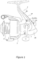
- Figure 1 is a side view of a spinning reel according to a first embodiment of the present invention;
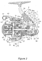
- Figure 2 is a cross-sectional side view of the spinning reel according to a first embodiment of the present invention;
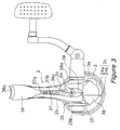
- Figure 3 is a rear view of the spinning reel according to a first embodiment of the present invention;
- Figure 4 is an exploded oblique view of a reel unit according to a first embodiment of the present invention;
- Figure 5 is an oblique view of the casing according to a first embodiment of the present invention;
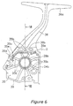
- Figure 6 is a side view of the lid portion according to a first embodiment of the present invention;
- Figure 7 is a cross-sectional view of the lid portion viewed along line VII-VII of Figure 6;
- Figure 8 is a cross-sectional side view of a spinning reel in accordance with a second embodiment; and
- Figure 9 is a plan view of a spinning reel in accordance with a second embodiment with a portion of the spinning reel removed.
-
- Selected embodiments of the present invention will now be explained with reference to the drawings. It will be apparent to those skilled in the art from this disclosure that the following description of the embodiments of the present invention is provided for illustration only, and not for the purpose of limiting the invention as defined by the appended claims and their equivalents.
- As shown in Figures 1 and 2, a spinning reel in accordance with a first embodiment of the present invention includes a
handle 1, areel unit 2 rotatably supporting thehandle 1 and mounted to a fishing rod, arotor 3, and aspool 4. Therotor 3 is for winding the fishing line around thespool 4, and is rotatably supported at the front of thereel unit 2. The fishing line is wound around the outer peripheral surface of thespool 4, which is disposed at the front of therotor 3 and can be shifted back and forth. It should be noted that thehandle 1 can be attached to the left side of thereel unit 2 as shown in Figure 1, or to the right side of thereel unit 2 as shown in Figure 2. - The
reel unit 2 principally includes, as shown in Figures 1 through 5, acasing 2a for supporting therotor 3 and thespool 4, alid portion 2b detachably screwed to thecasing 2a, acircular flange portion 2c having a first and asecond flange portions casing 2a and thelid portion 2b. - The
casing 2a is, for example, made of a polyamide-based synthetic resin reinforced by glass fibers, and is produced by injection molding. As shown in Figures 3 to 5, thecasing 2a has anopening 25 formed at its side, amechanism accommodating space 26 formed inside, arotation support portion 27 and a firsthandle support portion 28a. Therotation support portion 27 is formed so as to be arranged inside the circular hollow 3a formed at thereel unit 2 side of therotor 3, and is for rotatably supporting the rotation shaft (later-described pinion gear 12) of therotor 3. The firsthandle support portion 28a comprises a boss portion for supporting one end of thehandle shaft 10 that is the rotation shaft of thehandle 1. The upper portion (the portion near the mounting side of a fishing rod) of thecasing 2a has about the same thickness as an adjacent portion of acover member 35, but the lower portion bulges towards thelid portion 2b and is formed with a thickness greater than that of the upper portion. - The
openings 25 are provided in three portions except in the front portion, namely, the upper, the lower, and the rear portions, to mount various mechanisms in themechanism accommodating space 26. Theopenings 25 are formed with a step downward of the mid portion thereof according to the change in the thickness of thecasing 2a. As shown in Figure 2, themechanism accommodating space 26 accommodates arotor driving mechanism 5 for rotating therotor 3, and anoscillation mechanism 6 for winding up the fishing line uniformly by shifting thespool 4 back and forth. Therotation support portion 27 is formed unitarily with the front portion of the firstsemi-circular flange portion 24a that is also formed unitarily into a substantially columnar shape in front of themechanism accommodating space 26, and it has a throughhole 27a (Figure 2) through the center of which the pinion gear 12 passes. A one-way clutch 51 of the later-described reverserotation prevention mechanism 50 is screwed fast on the front face of therotation support portion 27. - At the rear of the
casing 2a, as shown in Figures 2 and 5, apivot support portion 28c is formed to support an operation shaft 54 of anoperation mechanism 52 of the reverserotation prevention mechanism 50. Thepivot support portion 28c is formed in a semi-circular shape protruding toward thelid portion 2b. The length of thepivot support portion 28c with respect to the direction of the operation shaft 54 is made shorter than in conventional configurations. Thepivot support portion 28c is arranged in aspace 35c formed inside of a trimmedportion 39 of thelid portion 2b. Therefore, it is sufficient if thelid portion 2b side has only a smallsemi-circular notch 35d for directly accommodating the operation shaft 54 instead of thepivot support portion 28c, so the relative strength of the notched portion of thelid portion 2b is maintained high. At the rear of thecasing 2a, a protruding quarter-circle boss portion 28d is formed contacting anoperation lever 53. Thelid portion 2b is also provided with aboss portion 35e having a similar shape. The twoboss portions - The
lid portion 2b is made of, for example, a polyamide-based synthetic resin reinforced by glass fibers, and is manufactured by injection molding. As shown in Figs 3, 4, 6, and 7, thelid portion 2b has a thin-walled cover portion 35 and a mountingleg portion 36. Thecover portion 35 is formed unitarily with thesecond flange portion 24b serving as a wall portion at the rotor such that thecover portion 35 covers theopening 25 of thecasing 2a, and that theflange portions cover portion 35 define a space in the interior. Theflange portions rotor 3, such that the flange portions can prevent foreign matter such as water or liquids from entering the hollow 3a. The mountingleg portion 36 extends upwardly from thecover portion 35. The upper portion of thecover portion 35 has about the same thickness as the adjacent portion of thecase 2a, and the lower portion becomes thinner as thecasing 2a bulges toward it. In the upper portion and the rear portion of thecover portion 35 except the front portion, a trimmedportion 39 is formed opposing theopening 25. In the trimmedportion 39, a step is formed so that it is in close contact with theopening 25. At the front of thecover portion 35, a substantially semi-circularsecond flange portion 24b of theflange portion 2c is formed. An inner side portion of thesecond flange portion 24b that protrudes inwardly has the function to serve as a wall portion for reinforcing thecover portion 35. On one side of thecover portion 35, a secondhandle support portion 28b comprising a boss portion for supporting the other end of thehandle shaft 10 is formed. From an upper portion of the trimmedportion 39 of thecover portion 35 toward thesecond handle support 28b, a varied-wall-thickness portion 35a, which is indicated by arrows in Figures 6 and 7, has an arched surface chamfered with a radius of, for example, about 6 mm so that the wall thickness does not change abruptly from the mountingleg portion 36. As a result of this, local stress concentrations can be relaxed, and at the same time, the fluid flow during resin molding is improved, preventing defective moldings. In addition, on the inner side face of the secondhandle support portion 28b, reinforcingribs 35b are radially formed. - The mounting
leg portion 36 is a solid, thick-walled member, one end of which extends both forward and backward and forms a fishing rod-mountingportion 36a. The boundary portion between thecover portion 35 and the mountingleg portion 36 is cut out at approximately half the thickness, and the upper portion of thecasing 2a is inserted into the cut-out portion so that the outer side faces are smoothly connected. In this cut-outportion 36b as well, a connectingportion 36c (Figure 7) connected with the trimmedportion 39 has an arched surface chamfered with a radius of, for example, about 3 mm in order to prevent stress concentration. - The
flange portion 2c is formed into a disk-like shape and arranged in substantially the same plane as the edge face of the circular hollow 3a formed in the rear of therotor 3, thus covering the circular hollow 3. As mentioned previously, theflange portion 2c includes the substantially semi-circularfirst flange portion 24a, which is formed unitarily with thecasing 2a, and the semicircularsecond flange portion 24b, which is formed unitarily with thecover portion 35 of thelid portion 2b and forms a circle together with thefirst flange portion 24a. Since theseflange portions casing 2a and thecover portion 35, the relative strength of thecasing 2a and thecover portion 35 can be maintained at a high degree. At the same time, deformations during the molding can be prevented and a high degree of precision can be maintained. - On the rear surface of the mounting
leg portion 36 of thereel unit 2, aname plate 37 is fixed. To a lower portion of the rear surface of the reel unit, aprotective cover 38 is mounted. - The
name plate 37 is made of a synthetic resin and is mounted to along groove 36d (Figure 2) formed on the mountingleg portion 36. Thename plate 37 has abody portion 37a arranged along the rear surface of the mountingleg portion 36, three protrudingportions 37b formed unitarily with thebody portion 37a and mounted to thelong groove 36d, and an interlockingtongue 37c formed at the lower end of thebody portion 37a and interlocking at an upper portion of thecasing 2a. The interlockingtongue 37c is fastened between thecasing 2a and thecover portion 35 so that it can reliably prevent the name plate from coming off. - The
protective cover 38 is, for example, made of a synthetic resin, such as ABS resin, that is metal-treated, or made of a stainless alloy so that it cannot be easily damaged, and it is for protecting the portion of thereel unit 2 that is most susceptible to damage. - As shown in Figure 2, the
rotor drive mechanism 5 includes a master gear 11 that is a face gear rotating with thehandle shaft 10 to which thehandle 1 is fixed, and a pinion gear 12 that meshes with the master gear 11. The pinion gear 12 that is the rotation shaft of therotor 3 is tubular, its front 12a penetrates the center of therotor 3 and is fixed to therotor 3 by anut 13. The pinion gear 12 is rotatably supported by thereel unit 2 at its mid-portion and rear end respectively by abearing 14a mounted to therotation support portion 27 and abearing 14b arranged further rearward. - The
oscillating mechanism 6 is a device that causes aspool shaft 15, coupled via adrag mechanism 60 to thespool 4 through its center, to reciprocate, which pumps thespool 4 in the same direction. Theoscillating mechanism 6 has: aworm shaft 21 disposed below and parallel to thespool shaft 15; aslider 22 that travels back and forth along theworm shaft 21; and anintermediate gear 23 fixed to the front end of theworm shaft 21. The rear end of thespool shaft 15 is fixed non-rotatably to theslider 22. The rear end of thespool shaft 15 is non-rotatably fixed to theslider 22. Theintermediate gear 23 meshes with the pinion gear 12 via a braking mechanism, which is not shown in the drawings. Thus, the speed with which theoscillating mechanism 6 shifts back and forth is slowed down, and the fishing line can be packed densely onto thespool 4. - The first and the second
handle support portions casing 2a and in which a bearing, which is not shown in the figures, is mounted. - As shown in Figure 2, the
rotor 3 includes acylindrical portion 30, and first andsecond rotor arms 31 and 32 opposing each other provided on the sides of thecylindrical portion 30. Thecylindrical portion 30 and the tworotor arms 31 and 32 are formed unitarily. - A
front wall 33 is provided at the front portion of thecylindrical portion 30, and a boss portion 33a is formed in the middle of thefront wall 33. The front portion 12a of the pinion gear 12 and thespool shaft 15 pass through a through-hole of the boss portion 33a. Anut 13 is arranged at the front portion of thefront wall 33, and thenut 13 is screwed into a thread portion at the front end of the pinion gear 12. In thecylindrical portion 30, the portion rearward from thefront wall 33 is a hollow 3a, and theflange portion 2c is formed unitarily with thecasing 2a and thelid portion 2b, flush with the rear end face of the hollow 3a. - A first bail-
support member 40 is fitted pivotably onto the outer peripheral side of the front end of thefirst rotor arm 31. Aline roller 41 for guiding fishing line onto thespool 4 is fitted to the front end of the first bail-support member 40. A second bail-support member 42 is fitted pivotally onto the outer peripheral side of the front end of the second rotor arm 32. Abail 43 is provided between theline roller 41 at the front end of the first bail-support member 40 and the second bail-support member 42. These first and second bail-support members line roller 41, and thebail 43 together form abail arm 44. - A reverse
rotation prevention mechanism 50 for prohibiting/releasing reversal of therotor 3 is disposed within thecylindrical portion 30 of therotor 3. The reverserotation prevention mechanism 50 has a roller-type one-way clutch 51, and anoperation mechanism 52 for switching the one-way clutch 51 between an operational state and a non-operational state. The outer race of the one-way clutch 51 is fixed to therotation support portion 27, and the inner race thereof is non-rotatably interlocked with the pinion gear 12. Theoperation mechanism 52 has anoperation lever 53 disposed between thecasing 2a and thelid portion 2b, and an operation shaft 54 provided with theoperation lever 53 at its rear end and mounted pivotably to thecasing 2a. Theoperation mechanism 52 can switch the one-way clutch 51 between the operational state and the non-operational state by pivoting theoperation lever 53 and thereby pivoting a cam protrusion (not shown in the figures) at the front end of the operation shaft 54. When the one-way clutch 51 is in the operational state, reverse rotation of therotor 3 is impossible, whereas when in the non-operational state, reverse rotation of therotor 3 is possible. - The
spool 4 is arranged between thefirst rotor arm 31 and the second rotor arm 32 of therotor 3, and is mounted to the front end of thespool shaft 15 with thedrag mechanism 60 interposed between thespool shaft 15 and thespool 4. Thespool 4 has abobbin trunk portion 4a onto which fishing line is wound, askirt portion 4b that is formed unitarily on the rear of thebobbin trunk portion 4a, and afront flange portion 4c fixed to the front end of thebobbin trunk portion 4a. - In the spinning reel thus configured, the
lid portion 2b, in which the thick-walledmounting leg portion 36 is formed unitarily with thecover portion 35, is provided separately from the thin-walled casing 2a for accommodating various drive portions. Therefore, a high degree of precision for thecasing 2a can be maintained, and a high degree of strength of the mountingleg portion 36 can also be maintained. In addition, the mountingleg portion 36 is formed unitarily with thecover portion 35, and therefore, the relative strength can be maintained with a simpler structure than if they are separately provided. Moreover, thefirst flange portion 24b, serving as a wall portion, is formed unitarily with thecover portion 35. Therefore, the entire cover portion has a box-like shape enclosing a space therein. Consequently, stress is distributed, and the relative strength of the cover portion is increased. Furthermore, because stress is distributed, deformations during the molding do not occur easily, and a high degree of precision can be maintained. For these reasons, even when thelid portion 2b including thecover portion 35 is made of a synthetic resin or the like, which has a low relative strength, a high degree of precision and relative strength can be maintained. In addition, since thelid portion 2b including thecover portion 35 is made of a synthetic resin, weight reduction can be achieved at low cost. - In the first embodiment, the
handle shaft 10 is supported by thecasing 2a and thelid portion 2b, but as shown in Figures 8 and 9, it is also possible to support ahandle shaft 110 by only thecasing 102a. - As seen from Figures 8 and 9, the spinning reel principally includes a
reel unit 102 to which thehandle 101 is rotatably mounted, arotor 103, and aspool 104. - The
reel unit 102 principally has acasing 102a for supporting therotor 103 and thespool 104, thelid portion 102b detachably screwed to thecasing 102a, and acircular flange portion 102c including first andsecond flange portions casing 102a and thelid portion 102b. - The
casing 2a is a thin-walled member made of, for example, an aluminum alloy. Thecasing 2a has anopening 125 formed at its side, a mechanismaccommodating space 126 formed inside, arotation support portion 127 that is formed so as to be arranged inside the circular hollow 103a formed at thereel unit 102 side of therotor 103 and rotatably supports the rotation shaft (pinion gear 112) of therotor 103, and ahandle support portion 128 comprising a boss portion for supporting thehandle shaft 110 that is the rotation shaft of thehandle 101. To thehandle support portion 128, twobearings handle shaft 110 is supported by only thecasing 102a. - The
lid portion 102b is made of, for example, an aluminum alloy. Thelid portion 102b has a thin-walled cover portion 135 for covering theopening 125 of thecasing 102a, and a mountingleg portion 136 extending upward from thecover portion 135. Thefirst flange portion 124b of theflange portion 102c is formed unitarily with the front portion of thecover portion 135. - Except that the
spool 104 is non-rotatably mounted to thespool shaft 115, the configuration of the spinning reel is substantially the same as that in the first embodiment, and is therefore not further elaborated upon. - Also with the
reel unit 102 thus configured, in thecover portion 135, thefirst flange portion 124b is formed unitarily with thecover portion 135 in addition to the portion covering theopening 125. Therefore, theentire cover portion 135 has a box-like shape enclosing a space therein. Consequently, stress is distributed, and the relative strength of thecover portion 135 is increased. Furthermore, because stress is distributed, deformations during the molding do not occur easily, and a high degree of precision can be maintained. For these reasons, even when thelid portion 102b including thecover portion 135 is made of an aluminum alloy or the like, which has a low relative strength, a high degree of precision and relative strength can be maintained. In addition, since thelid portion 102b including thecover portion 35 is made of alight weight metal such as an aluminum alloy, weight reduction can be achieved at low cost. -
- (a) Types of spinning reels are not limited to the foregoing embodiments. The present invention can be suitably applied to spinning reels having a drag mechanism or a braking mechanism having a brake lever instead of the reverse rotation prevention mechanism.
- (b) The shapes of the mounting leg portion and the cover portion are not limited to the foregoing embodiments.
- (c) The foregoing embodiments have described
for the case that the
first flange portion 24a and thesecond flange portion 24b are formed unitarily with thecasing 2a and thecover portion 35, but as long as the wall portion that is the inner portion protruding inward of thesecond flange portion 24b is formed unitarily with thecover portion 35, other portions may be formed separately. -
- According to the present invention, in the cover portion, a wall portion is formed unitarily therewith at the side to which the rotor is to be mounted, in addition to the portion that covers the opening, and therefore, the entire cover portion has a box-like shape enclosing a space therein. Thus, stress is distributed and the relative strength of the cover portion is increased. Moreover, because stress is distributed, deformations do not occur easily during the molding, and a high degree of precision can be maintained. Consequently, even when the lid portion including the cover portion is made of a synthetic resin or an aluminum alloy, which has a low relative strength, it is possible to maintain a high degree of precision and relative strength. In addition, if the lid portion including the cover portion is made of an aluminum alloy or a synthetic resin, weight reduction can be achieved at low cost.
- As used herein, the following directional terms "forward," "rearward," "above," "downward," "vertical," "horizontal," "below" and "transverse" as well as any other similar directional terms refer to those directions of a device equipped with the present invention. Accordingly, these terms, as utilized to describe the present invention should be interpreted relative to a device equipped with the present invention.
- The terms of degree such as "substantially," "about" and "approximately" as used herein mean a reasonable amount of deviation of the modified term such that the end result is not significantly changed. These terms should be construed as including a deviation of at least ± 5% of the modified term if this deviation would not negate the meaning of the word it modifies.
- This application claims priority to Japanese Patent Application No. 2002-28219. The entire disclosure of Japanese Patent Application No. 2002-28219 is hereby incorporated herein by reference.
- While only selected embodiments have been chosen to illustrate the present invention, it will be apparent to those skilled in the art from this disclosure that various changes and modifications can be made herein without departing from the scope of the invention as defined in the appended claims. Furthermore, the foregoing description of the embodiments according to the present invention are provided for illustration only, and not for the purpose of limiting the invention as defined by the appended claims and their equivalents.
Claims (12)
- A reel unit (2,102) for a spinning reel that is mounted to a fishing rod and has a rotor (3,103) that rotates in cooperation with rotation of a handle (1,101) for winding fishing line onto a spool (4,104), said reel unit comprising:a casing (2a,102a) forming a mechanism accommodating space (26,126) inside, said casing including an opening (25,125) formed at its side and a rotation support portion (27,127) for supporting a rotation shaft of the rotor, said rotation support portion being adapted to be arranged inside a circular hollow (3a,103a) formed at a reel unit side of the rotor;a lid portion (2b,102b) having a cover portion (35,135) and a mounting leg portion (36,136), said cover portion being detachably fixed to said casing to cover said opening of said casing, said mounting leg portion extending from said cover portion and having a front end to which the fishing rod can be attached; anda wall portion formed unitarily with said lid portion on a rotor side of said lid portion such that said wall portion and said lid portion define a space inside.
- The reel unit for a spinning reel as set forth in Claim 1, further comprisinga substantially circular flange portion having a first flange portion (24a,124a) and a second flange portion (24b,124b), said first flange portion being arranged on substantially the same plane as the end face of the hollow (3a,103a) and adjacent to said casing (2a,102a), said second flange portion being provided with said wall portion such that said first and second flange portions cover the hollow together with said first flange portion.
- The reel unit for a spinning reel as set forth in Claim 2, whereinsaid second flange portion (24b,124b) is formed unitarily with said wall portion.
- The reel unit for a spinning reel as set forth in Claim 2 or Claim 3, whereinsaid first flange portion (24a,124a) is formed unitarily with said casing (2a,102a).
- The reel unit for a spinning reel as set forth in any preceding Claim, whereinsaid casing and said lid portion are made of a synthetic resin.
- The reel unit for a spinning reel as set forth in any of Claims 1 to 4, whereinsaid casing and said lid portion are made of a light weight metal.
- The reel unit for a spinning reel as set forth in any of Claims 2 to 6, whereinsaid cover portion (35,135) has a trimmed portion (39) formed continuously with said second flange portion (24b, 124b) and formed on a circumference opposing said opening (25,125) of said casing (2a,102a).
- The reel unit for a spinning reel as set forth in any preceding Claim, whereinsaid lid portion (2b,102b) has a handle support portion (128) for supporting the handle (1,101).
- The reel unit for a spinning reel as set forth in Claim 8, whereinsaid casing (2a,102a) has a handle support portion (128) for supporting the handle (1,101).
- The reel unit for a spinning reel as set forth in Claim 8 or Claim 9, whereinsaid cover portion (35,135) further includes reinforcing ribs that are formed on an inner side of said handle support portion.
- A spinning reel adapted to be mounted to a fishing rod, comprising:a handle (1,101);a reel unit (2,102) according to any preceding Claim rotatably supporting said handle;a rotor (3,103) rotatably supported at a front of said reel unit and having the circular hollow (3a,103a) on a reel unit side; anda spool (4,104) disposed at a front of said rotor so as to be shiftable back and forth.
- The spinning reel as set forth in Claim 11, further comprisinga flange portion having a first flange portion (24a,124a) and a second flange portion (24b,124b), said first flange portion being arranged adjacent to said casing (2a,102a), said second flange portion provided with said wall portion such that said first and second flange portions cover said hollow (3a,103a) of said rotor (3,103) together with said first flange portion.
Applications Claiming Priority (2)
| Application Number | Priority Date | Filing Date | Title |
|---|---|---|---|
| JP2002028219A JP2003225039A (en) | 2002-02-05 | 2002-02-05 | Spinning reel reel body |
| JP2002028219 | 2002-02-05 |
Publications (2)
| Publication Number | Publication Date |
|---|---|
| EP1332672A1 true EP1332672A1 (en) | 2003-08-06 |
| EP1332672B1 EP1332672B1 (en) | 2006-07-26 |
Family
ID=19192430
Family Applications (1)
| Application Number | Title | Priority Date | Filing Date |
|---|---|---|---|
| EP03394005A Expired - Lifetime EP1332672B1 (en) | 2002-02-05 | 2003-01-08 | Reel unit for spinning reel |
Country Status (10)
| Country | Link |
|---|---|
| US (1) | US6955316B2 (en) |
| EP (1) | EP1332672B1 (en) |
| JP (1) | JP2003225039A (en) |
| KR (1) | KR100983928B1 (en) |
| CN (1) | CN1317946C (en) |
| AT (1) | ATE333790T1 (en) |
| DE (1) | DE60306967T2 (en) |
| MY (1) | MY133407A (en) |
| SG (1) | SG123547A1 (en) |
| TW (1) | TWI264282B (en) |
Cited By (5)
| Publication number | Priority date | Publication date | Assignee | Title |
|---|---|---|---|---|
| US6857588B1 (en) | 2003-10-27 | 2005-02-22 | Okuma Fishing Tackle Co., Ltd. | Spinning reel having cover for decoration |
| EP1525792A1 (en) * | 2003-10-20 | 2005-04-27 | Okuma Fishing Tackle Co., Ltd. | Spinning reel |
| EP1525793A1 (en) * | 2003-10-24 | 2005-04-27 | Okuma Fishing Tackle Co., Ltd. | Spinning reel |
| EP1461999A3 (en) * | 2003-02-05 | 2005-07-27 | Shimano Inc. | Reel unit for spinning reel |
| US6932291B2 (en) | 2003-10-27 | 2005-08-23 | Okuma Fishing Tackle Co., Ltd. | Spinning reel |
Families Citing this family (16)
| Publication number | Priority date | Publication date | Assignee | Title |
|---|---|---|---|---|
| JP4015901B2 (en) * | 2002-07-31 | 2007-11-28 | 株式会社シマノ | Spinning reel body |
| JP3746033B2 (en) * | 2002-10-25 | 2006-02-15 | 株式会社シマノ | Spinning reel body |
| US7028937B2 (en) * | 2003-02-05 | 2006-04-18 | Shimano Inc. | Reel unit for spinning reel |
| JP4314108B2 (en) * | 2003-08-20 | 2009-08-12 | 株式会社シマノ | Spinning reel |
| US7066419B2 (en) * | 2003-09-10 | 2006-06-27 | Shimano Inc. | Reel unit for spinning reel |
| CN100377641C (en) * | 2004-08-11 | 2008-04-02 | 上海达金兴业渔具有限公司 | Fishing wire winder with double side covers |
| JP4709019B2 (en) * | 2006-01-25 | 2011-06-22 | グローブライド株式会社 | Fishing spinning reel |
| US7275705B1 (en) | 2006-09-07 | 2007-10-02 | Shakespeare Company, Llc | Spinning reel having two-piece frame and leg assembly with concealable attachment points |
| SG144041A1 (en) * | 2006-12-21 | 2008-07-29 | Shimano Kk | Reel unit of spinning reel |
| JP5324819B2 (en) * | 2008-05-12 | 2013-10-23 | シマノコンポネンツ マレーシア エスディーエヌ.ビーエッチディー. | Lever drag reel reverse rotation prevention mechanism |
| JP6010384B2 (en) * | 2012-08-02 | 2016-10-19 | 株式会社シマノ | Fishing reel spool attachment / detachment mechanism |
| JP6046496B2 (en) * | 2013-01-07 | 2016-12-14 | 株式会社シマノ | Spinning reel |
| JP2016208860A (en) * | 2015-04-30 | 2016-12-15 | グローブライド株式会社 | Fishing reel |
| JP6688603B2 (en) * | 2015-12-14 | 2020-04-28 | 株式会社シマノ | Spinning reel rotor and spinning reel |
| JP6664975B2 (en) * | 2016-01-25 | 2020-03-13 | 株式会社シマノ | Spinning reel rotor for fishing |
| WO2020257651A1 (en) | 2019-06-21 | 2020-12-24 | Biz Outdoors, Inc. | Left handed fishing reel |
Citations (4)
| Publication number | Priority date | Publication date | Assignee | Title |
|---|---|---|---|---|
| EP0803191A2 (en) * | 1996-04-25 | 1997-10-29 | Shimano Inc. | Frame structure for spinning reel |
| JPH101836A (en) * | 1996-06-18 | 1998-01-06 | Mitsubishi Rayon Co Ltd | Spun yarn-like composite false twist yarn and method for producing the same |
| JP2001333669A (en) * | 2000-05-31 | 2001-12-04 | Shimano Inc | Spinning reel reel body |
| JP2002028219A (en) | 2001-06-14 | 2002-01-29 | Showa Denko Kk | Plugs for infusion containers |
Family Cites Families (10)
| Publication number | Priority date | Publication date | Assignee | Title |
|---|---|---|---|---|
| JPS644836A (en) * | 1987-06-29 | 1989-01-10 | Hitachi Ltd | Overflow preventing system for data flow controller |
| US5350130A (en) * | 1991-10-15 | 1994-09-27 | Shimano Inc. | Spinning reel with removable cover |
| JP3066990B2 (en) * | 1991-11-26 | 2000-07-17 | 株式会社シマノ | Spinning reel and manufacturing method thereof |
| JP2561243Y2 (en) * | 1992-03-06 | 1998-01-28 | 株式会社シマノ | Spinning reel |
| US5443571A (en) * | 1992-07-15 | 1995-08-22 | Zebco Corporation | Wrap around side cover for a spinning fishing reel |
| JPH099828A (en) * | 1995-06-30 | 1997-01-14 | Shimano Inc | Spinning reel |
| FR2759543B1 (en) * | 1997-02-17 | 1999-04-16 | Mitchell Sports | WATERPROOF REEL |
| US6059211A (en) * | 1997-07-14 | 2000-05-09 | Charles C. Worth Corporation | Fishing reel with reel body of unitary sidewall construction |
| JP3840008B2 (en) | 1999-10-13 | 2006-11-01 | 株式会社シマノ | Spinning reel body |
| US6641070B1 (en) * | 2001-10-25 | 2003-11-04 | Shakespeare Company | Spincast fishing reel having multipiece rear cover assembly |
-
2002
- 2002-02-05 JP JP2002028219A patent/JP2003225039A/en active Pending
- 2002-12-19 US US10/322,617 patent/US6955316B2/en not_active Expired - Lifetime
- 2002-12-24 TW TW091137167A patent/TWI264282B/en not_active IP Right Cessation
- 2002-12-27 MY MYPI20024893A patent/MY133407A/en unknown
- 2002-12-30 SG SG200207854A patent/SG123547A1/en unknown
-
2003
- 2003-01-08 AT AT03394005T patent/ATE333790T1/en not_active IP Right Cessation
- 2003-01-08 DE DE60306967T patent/DE60306967T2/en not_active Expired - Lifetime
- 2003-01-08 EP EP03394005A patent/EP1332672B1/en not_active Expired - Lifetime
- 2003-01-31 CN CNB031031617A patent/CN1317946C/en not_active Expired - Fee Related
- 2003-02-05 KR KR1020030007075A patent/KR100983928B1/en not_active Expired - Fee Related
Patent Citations (4)
| Publication number | Priority date | Publication date | Assignee | Title |
|---|---|---|---|---|
| EP0803191A2 (en) * | 1996-04-25 | 1997-10-29 | Shimano Inc. | Frame structure for spinning reel |
| JPH101836A (en) * | 1996-06-18 | 1998-01-06 | Mitsubishi Rayon Co Ltd | Spun yarn-like composite false twist yarn and method for producing the same |
| JP2001333669A (en) * | 2000-05-31 | 2001-12-04 | Shimano Inc | Spinning reel reel body |
| JP2002028219A (en) | 2001-06-14 | 2002-01-29 | Showa Denko Kk | Plugs for infusion containers |
Non-Patent Citations (1)
| Title |
|---|
| PATENT ABSTRACTS OF JAPAN vol. 2002, no. 04 4 August 2002 (2002-08-04) * |
Cited By (5)
| Publication number | Priority date | Publication date | Assignee | Title |
|---|---|---|---|---|
| EP1461999A3 (en) * | 2003-02-05 | 2005-07-27 | Shimano Inc. | Reel unit for spinning reel |
| EP1525792A1 (en) * | 2003-10-20 | 2005-04-27 | Okuma Fishing Tackle Co., Ltd. | Spinning reel |
| EP1525793A1 (en) * | 2003-10-24 | 2005-04-27 | Okuma Fishing Tackle Co., Ltd. | Spinning reel |
| US6857588B1 (en) | 2003-10-27 | 2005-02-22 | Okuma Fishing Tackle Co., Ltd. | Spinning reel having cover for decoration |
| US6932291B2 (en) | 2003-10-27 | 2005-08-23 | Okuma Fishing Tackle Co., Ltd. | Spinning reel |
Also Published As
| Publication number | Publication date |
|---|---|
| DE60306967D1 (en) | 2006-09-07 |
| JP2003225039A (en) | 2003-08-12 |
| US20030146325A1 (en) | 2003-08-07 |
| SG123547A1 (en) | 2006-07-26 |
| US6955316B2 (en) | 2005-10-18 |
| MY133407A (en) | 2007-11-30 |
| CN1436453A (en) | 2003-08-20 |
| TWI264282B (en) | 2006-10-21 |
| KR20030066457A (en) | 2003-08-09 |
| DE60306967T2 (en) | 2007-02-15 |
| ATE333790T1 (en) | 2006-08-15 |
| KR100983928B1 (en) | 2010-09-28 |
| TW200302696A (en) | 2003-08-16 |
| EP1332672B1 (en) | 2006-07-26 |
| CN1317946C (en) | 2007-05-30 |
Similar Documents
| Publication | Publication Date | Title |
|---|---|---|
| EP1332672B1 (en) | Reel unit for spinning reel | |
| KR20090028440A (en) | Reel body of spinning reel | |
| US7118059B2 (en) | Reel unit for spinning reel | |
| US20020125358A1 (en) | Water-sealing component assembly | |
| KR100433369B1 (en) | Frame structure of spinning reel | |
| US6880776B2 (en) | Reel unit for spinning reel | |
| KR101058363B1 (en) | Master Gear of Spinning Reel | |
| US6857587B2 (en) | Worm shaft attachment structure for spinning reel | |
| KR20040071628A (en) | Handle attachment structure for fishing reel | |
| US6854677B2 (en) | Spinning-reel sounding mechanism | |
| US7007880B2 (en) | Fishing line guide mechanism for spinning reel | |
| EP1346635B1 (en) | Spinning reel rotor | |
| EP1915905B1 (en) | Spool for spinning reel and spinning reel | |
| JP4121869B2 (en) | Spinning reel body | |
| JP7391062B2 (en) | spinning reel for fishing | |
| JP2004081153A (en) | Reel body of spinning reel | |
| JP2001333669A (en) | Spinning reel reel body | |
| JPH11196726A (en) | Spinning reel rotor drive mechanism |
Legal Events
| Date | Code | Title | Description |
|---|---|---|---|
| PUAI | Public reference made under article 153(3) epc to a published international application that has entered the european phase |
Free format text: ORIGINAL CODE: 0009012 |
|
| AK | Designated contracting states |
Designated state(s): AT BE BG CH CY CZ DE DK EE ES FI FR GB GR HU IE IT LI LU MC NL PT SE SI SK TR |
|
| AX | Request for extension of the european patent |
Extension state: AL LT LV MK RO |
|
| 17P | Request for examination filed |
Effective date: 20030728 |
|
| AKX | Designation fees paid |
Designated state(s): AT BE BG CH CY CZ DE DK EE ES FI FR GB GR HU IE IT LI LU MC NL PT SE SI SK TR |
|
| GRAP | Despatch of communication of intention to grant a patent |
Free format text: ORIGINAL CODE: EPIDOSNIGR1 |
|
| GRAS | Grant fee paid |
Free format text: ORIGINAL CODE: EPIDOSNIGR3 |
|
| GRAA | (expected) grant |
Free format text: ORIGINAL CODE: 0009210 |
|
| AK | Designated contracting states |
Kind code of ref document: B1 Designated state(s): AT BE BG CH CY CZ DE DK EE ES FI FR GB GR HU IE IT LI LU MC NL PT SE SI SK TR |
|
| PG25 | Lapsed in a contracting state [announced via postgrant information from national office to epo] |
Ref country code: IT Free format text: LAPSE BECAUSE OF FAILURE TO SUBMIT A TRANSLATION OF THE DESCRIPTION OR TO PAY THE FEE WITHIN THE PRE;WARNING: LAPSES OF ITALIAN PATENTS WITH EFFECTIVE DATE BEFORE 2007 MAY HAVE OCCURRED AT ANY TIME BEFORE 2007. THE CORRECT EFFECTIVE DATE MAY BE DIFFERENT FROM THE ONE RECORDED.SCRIBED TIME-LIMIT Effective date: 20060726 Ref country code: SK Free format text: LAPSE BECAUSE OF FAILURE TO SUBMIT A TRANSLATION OF THE DESCRIPTION OR TO PAY THE FEE WITHIN THE PRESCRIBED TIME-LIMIT Effective date: 20060726 Ref country code: FI Free format text: LAPSE BECAUSE OF FAILURE TO SUBMIT A TRANSLATION OF THE DESCRIPTION OR TO PAY THE FEE WITHIN THE PRESCRIBED TIME-LIMIT Effective date: 20060726 Ref country code: BE Free format text: LAPSE BECAUSE OF FAILURE TO SUBMIT A TRANSLATION OF THE DESCRIPTION OR TO PAY THE FEE WITHIN THE PRESCRIBED TIME-LIMIT Effective date: 20060726 Ref country code: AT Free format text: LAPSE BECAUSE OF FAILURE TO SUBMIT A TRANSLATION OF THE DESCRIPTION OR TO PAY THE FEE WITHIN THE PRESCRIBED TIME-LIMIT Effective date: 20060726 Ref country code: CZ Free format text: LAPSE BECAUSE OF FAILURE TO SUBMIT A TRANSLATION OF THE DESCRIPTION OR TO PAY THE FEE WITHIN THE PRESCRIBED TIME-LIMIT Effective date: 20060726 Ref country code: NL Free format text: LAPSE BECAUSE OF FAILURE TO SUBMIT A TRANSLATION OF THE DESCRIPTION OR TO PAY THE FEE WITHIN THE PRESCRIBED TIME-LIMIT Effective date: 20060726 Ref country code: CH Free format text: LAPSE BECAUSE OF FAILURE TO SUBMIT A TRANSLATION OF THE DESCRIPTION OR TO PAY THE FEE WITHIN THE PRESCRIBED TIME-LIMIT Effective date: 20060726 Ref country code: SI Free format text: LAPSE BECAUSE OF FAILURE TO SUBMIT A TRANSLATION OF THE DESCRIPTION OR TO PAY THE FEE WITHIN THE PRESCRIBED TIME-LIMIT Effective date: 20060726 Ref country code: LI Free format text: LAPSE BECAUSE OF FAILURE TO SUBMIT A TRANSLATION OF THE DESCRIPTION OR TO PAY THE FEE WITHIN THE PRESCRIBED TIME-LIMIT Effective date: 20060726 |
|
| REG | Reference to a national code |
Ref country code: GB Ref legal event code: FG4D |
|
| RAP2 | Party data changed (patent owner data changed or rights of a patent transferred) |
Owner name: SHIMANO INC. |
|
| REG | Reference to a national code |
Ref country code: CH Ref legal event code: EP |
|
| REG | Reference to a national code |
Ref country code: IE Ref legal event code: FG4D |
|
| REF | Corresponds to: |
Ref document number: 60306967 Country of ref document: DE Date of ref document: 20060907 Kind code of ref document: P |
|
| NLT2 | Nl: modifications (of names), taken from the european patent patent bulletin |
Owner name: SHIMANO INC. Effective date: 20060802 |
|
| PG25 | Lapsed in a contracting state [announced via postgrant information from national office to epo] |
Ref country code: DK Free format text: LAPSE BECAUSE OF FAILURE TO SUBMIT A TRANSLATION OF THE DESCRIPTION OR TO PAY THE FEE WITHIN THE PRESCRIBED TIME-LIMIT Effective date: 20061026 Ref country code: BG Free format text: LAPSE BECAUSE OF FAILURE TO SUBMIT A TRANSLATION OF THE DESCRIPTION OR TO PAY THE FEE WITHIN THE PRESCRIBED TIME-LIMIT Effective date: 20061026 Ref country code: SE Free format text: LAPSE BECAUSE OF FAILURE TO SUBMIT A TRANSLATION OF THE DESCRIPTION OR TO PAY THE FEE WITHIN THE PRESCRIBED TIME-LIMIT Effective date: 20061026 |
|
| PG25 | Lapsed in a contracting state [announced via postgrant information from national office to epo] |
Ref country code: ES Free format text: LAPSE BECAUSE OF FAILURE TO SUBMIT A TRANSLATION OF THE DESCRIPTION OR TO PAY THE FEE WITHIN THE PRESCRIBED TIME-LIMIT Effective date: 20061106 |
|
| PG25 | Lapsed in a contracting state [announced via postgrant information from national office to epo] |
Ref country code: PT Free format text: LAPSE BECAUSE OF FAILURE TO SUBMIT A TRANSLATION OF THE DESCRIPTION OR TO PAY THE FEE WITHIN THE PRESCRIBED TIME-LIMIT Effective date: 20061226 |
|
| NLV1 | Nl: lapsed or annulled due to failure to fulfill the requirements of art. 29p and 29m of the patents act | ||
| PG25 | Lapsed in a contracting state [announced via postgrant information from national office to epo] |
Ref country code: IE Free format text: LAPSE BECAUSE OF NON-PAYMENT OF DUE FEES Effective date: 20070108 |
|
| PG25 | Lapsed in a contracting state [announced via postgrant information from national office to epo] |
Ref country code: MC Free format text: LAPSE BECAUSE OF NON-PAYMENT OF DUE FEES Effective date: 20070131 |
|
| EN | Fr: translation not filed | ||
| PLBE | No opposition filed within time limit |
Free format text: ORIGINAL CODE: 0009261 |
|
| STAA | Information on the status of an ep patent application or granted ep patent |
Free format text: STATUS: NO OPPOSITION FILED WITHIN TIME LIMIT |
|
| 26N | No opposition filed |
Effective date: 20070427 |
|
| PG25 | Lapsed in a contracting state [announced via postgrant information from national office to epo] |
Ref country code: FR Free format text: LAPSE BECAUSE OF FAILURE TO SUBMIT A TRANSLATION OF THE DESCRIPTION OR TO PAY THE FEE WITHIN THE PRESCRIBED TIME-LIMIT Effective date: 20070511 Ref country code: GR Free format text: LAPSE BECAUSE OF FAILURE TO SUBMIT A TRANSLATION OF THE DESCRIPTION OR TO PAY THE FEE WITHIN THE PRESCRIBED TIME-LIMIT Effective date: 20061027 |
|
| PG25 | Lapsed in a contracting state [announced via postgrant information from national office to epo] |
Ref country code: EE Free format text: LAPSE BECAUSE OF FAILURE TO SUBMIT A TRANSLATION OF THE DESCRIPTION OR TO PAY THE FEE WITHIN THE PRESCRIBED TIME-LIMIT Effective date: 20060726 |
|
| PG25 | Lapsed in a contracting state [announced via postgrant information from national office to epo] |
Ref country code: FR Free format text: LAPSE BECAUSE OF FAILURE TO SUBMIT A TRANSLATION OF THE DESCRIPTION OR TO PAY THE FEE WITHIN THE PRESCRIBED TIME-LIMIT Effective date: 20060726 |
|
| PG25 | Lapsed in a contracting state [announced via postgrant information from national office to epo] |
Ref country code: LU Free format text: LAPSE BECAUSE OF NON-PAYMENT OF DUE FEES Effective date: 20070108 Ref country code: CY Free format text: LAPSE BECAUSE OF FAILURE TO SUBMIT A TRANSLATION OF THE DESCRIPTION OR TO PAY THE FEE WITHIN THE PRESCRIBED TIME-LIMIT Effective date: 20060726 |
|
| PG25 | Lapsed in a contracting state [announced via postgrant information from national office to epo] |
Ref country code: HU Free format text: LAPSE BECAUSE OF FAILURE TO SUBMIT A TRANSLATION OF THE DESCRIPTION OR TO PAY THE FEE WITHIN THE PRESCRIBED TIME-LIMIT Effective date: 20070127 Ref country code: TR Free format text: LAPSE BECAUSE OF FAILURE TO SUBMIT A TRANSLATION OF THE DESCRIPTION OR TO PAY THE FEE WITHIN THE PRESCRIBED TIME-LIMIT Effective date: 20060726 |
|
| PGFP | Annual fee paid to national office [announced via postgrant information from national office to epo] |
Ref country code: IT Payment date: 20100116 Year of fee payment: 8 |
|
| PG25 | Lapsed in a contracting state [announced via postgrant information from national office to epo] |
Ref country code: IT Free format text: LAPSE BECAUSE OF NON-PAYMENT OF DUE FEES Effective date: 20110108 |
|
| PGFP | Annual fee paid to national office [announced via postgrant information from national office to epo] |
Ref country code: DE Payment date: 20120104 Year of fee payment: 10 |
|
| PGFP | Annual fee paid to national office [announced via postgrant information from national office to epo] |
Ref country code: GB Payment date: 20120104 Year of fee payment: 10 |
|
| GBPC | Gb: european patent ceased through non-payment of renewal fee |
Effective date: 20130108 |
|
| PG25 | Lapsed in a contracting state [announced via postgrant information from national office to epo] |
Ref country code: DE Free format text: LAPSE BECAUSE OF NON-PAYMENT OF DUE FEES Effective date: 20130801 |
|
| REG | Reference to a national code |
Ref country code: DE Ref legal event code: R119 Ref document number: 60306967 Country of ref document: DE Effective date: 20130801 |
|
| PG25 | Lapsed in a contracting state [announced via postgrant information from national office to epo] |
Ref country code: GB Free format text: LAPSE BECAUSE OF NON-PAYMENT OF DUE FEES Effective date: 20130108 |