EP1332665A1 - Mechanical device with oscillating blades which may be moved on all the orthogonal planes - Google Patents
Mechanical device with oscillating blades which may be moved on all the orthogonal planes Download PDFInfo
- Publication number
- EP1332665A1 EP1332665A1 EP03425019A EP03425019A EP1332665A1 EP 1332665 A1 EP1332665 A1 EP 1332665A1 EP 03425019 A EP03425019 A EP 03425019A EP 03425019 A EP03425019 A EP 03425019A EP 1332665 A1 EP1332665 A1 EP 1332665A1
- Authority
- EP
- European Patent Office
- Prior art keywords
- unit
- oscillating
- blades
- bevel gear
- support
- Prior art date
- Legal status (The legal status is an assumption and is not a legal conclusion. Google has not performed a legal analysis and makes no representation as to the accuracy of the status listed.)
- Granted
Links
- 238000005520 cutting process Methods 0.000 claims description 10
- 230000008878 coupling Effects 0.000 claims description 8
- 238000010168 coupling process Methods 0.000 claims description 8
- 238000005859 coupling reaction Methods 0.000 claims description 8
- 238000009966 trimming Methods 0.000 claims description 7
- 230000005540 biological transmission Effects 0.000 claims description 6
- 208000032369 Primary transmission Diseases 0.000 claims description 4
- 208000032370 Secondary transmission Diseases 0.000 claims description 2
- 230000006978 adaptation Effects 0.000 claims description 2
- 230000036316 preload Effects 0.000 claims 2
- 125000006850 spacer group Chemical group 0.000 claims 1
- 238000009313 farming Methods 0.000 abstract 1
- 238000010413 gardening Methods 0.000 abstract 1
- 241001494496 Leersia Species 0.000 description 1
- 238000010586 diagram Methods 0.000 description 1
- 238000012423 maintenance Methods 0.000 description 1
- 239000002184 metal Substances 0.000 description 1
Images






Classifications
-
- A—HUMAN NECESSITIES
- A01—AGRICULTURE; FORESTRY; ANIMAL HUSBANDRY; HUNTING; TRAPPING; FISHING
- A01G—HORTICULTURE; CULTIVATION OF VEGETABLES, FLOWERS, RICE, FRUIT, VINES, HOPS OR SEAWEED; FORESTRY; WATERING
- A01G3/00—Cutting implements specially adapted for horticultural purposes; Delimbing standing trees
- A01G3/04—Apparatus for trimming hedges, e.g. hedge shears
- A01G3/047—Apparatus for trimming hedges, e.g. hedge shears portable
- A01G3/053—Apparatus for trimming hedges, e.g. hedge shears portable motor-driven
Definitions
- the invention concerns a mechanical device with oscillating blades which are moved in such a way that the operator can easily clear bushes and branches, cut grass and mow a lawn.
- the blades can be adjusted to work on all orthogonal planes so that the operator can reach any required position with respect to the areas to be cut.
- the most innovative aspect of this invention is the configuration of the mechanical device, for which a specific claim will be made below, since it may be used in mechanical devices which must be moved on orthogonal planes.
- the invention may be classified in the technical sector of electromechanical devices and in the field of application of agricultural and garden tools.
- the mechanical device covered by this invention is easily installed on the existing bevel gear pair of any trimmer. As explained below, as well as mowing at ground level, it enables, with the blades set at approximately 90°, all the operations for the vertical trimming of hedges as well as cutting to the top. This is carried out whilst walking along the sides of the hedge thereby guaranteeing safety for the operator and accuracy in the cutting operations.
- the mechanism is powered by any type of trimming machine.
- the mechanism By means of a primary transmission axis 14, 16, 31, the mechanism enters the reduction unit 9, 10 where the reduction ratio is applied.
- Collar 10 is held on two rings 6 pre-loaded by spring 7 held by seger 8. This all enables a controlled sliding of collar 10. This is necessary so that when the blade of the mechanism encounters a hard obstacle (e.g. metal wire) the unit starts to slide so that the collar 10 runs on the runners 6, thereby avoiding any damage to the mechanism, which would have blocked blades on one side and an operational motor on the other. The operator avoids the obstacle and returns to work.
- a hard obstacle e.g. metal wire
- the secondary shaft 13 which takes its movement from reduction unit 11, transmits the movement to two rocking cams 12.
- the rocking cams 12 are held in two rods 25 and 26 which reach the alternative movement in a coaxial rotational joint 21 and 20, where the rods 25 and 26 transfer the alternative movement regardless of the position of the rotating joint 21, 20.
- the blades 24 are fixed on the rotating joint 21, 20 by means of the screws 23. Since the blades are easily fixed they may be easily removed for maintenance purposes. In fact, the blade unit, as shown in Fig. 3, slides from the rotational unit which provides the transmission movement. All the parts with alternative movement are out of phase by 180° and balanced with each other in order to minimise the vibrations.
- the movement on the horizontal plane, in order to adjust the mechanism at approximately 90° intervals is carried out by unlocking a ratchet fixed on collar 29 and releasing it in the desired position, usually by means of a pushbutton command.
- the ratchet is composed of a lever on one side of which are the ratchets for locking support ring 29 and on the other side of which is a knob to unlock the clamp.
- the position is fixed by means of a spring 37 which holds the ratchet.
Landscapes
- Life Sciences & Earth Sciences (AREA)
- Biodiversity & Conservation Biology (AREA)
- Ecology (AREA)
- Forests & Forestry (AREA)
- Environmental Sciences (AREA)
- Harvester Elements (AREA)
- Control Of Motors That Do Not Use Commutators (AREA)
- Soil Working Implements (AREA)
- Consolidation Of Soil By Introduction Of Solidifying Substances Into Soil (AREA)
- Structures Of Non-Positive Displacement Pumps (AREA)
- Pressure Welding/Diffusion-Bonding (AREA)
- Coating Apparatus (AREA)
Abstract
Description
- The invention concerns a mechanical device with oscillating blades which are moved in such a way that the operator can easily clear bushes and branches, cut grass and mow a lawn. The blades can be adjusted to work on all orthogonal planes so that the operator can reach any required position with respect to the areas to be cut.
- As can be clearly seen, the most innovative aspect of this invention is the configuration of the mechanical device, for which a specific claim will be made below, since it may be used in mechanical devices which must be moved on orthogonal planes.
- The invention may be classified in the technical sector of electromechanical devices and in the field of application of agricultural and garden tools.
- Until now, automatic hedge trimmers and lawnmowers always included another tool. The operator removed the bevel gear pair installed on the most-commonly used machines in this sector and installed a mechanism fitted with blades which always had limitations for the performance of the work. In fact, the trimming of the upper sides of hedges was carried out with these machines with the operator in front of the hedge. This was very uncomfortable for the operator since he had to walk sideways without knowing where to place his feet, which could be dangerous and also lead to inaccurate trimming.
- The mechanical device covered by this invention, and subject of this request for a patent, is easily installed on the existing bevel gear pair of any trimmer. As explained below, as well as mowing at ground level, it enables, with the blades set at approximately 90°, all the operations for the vertical trimming of hedges as well as cutting to the top. This is carried out whilst walking along the sides of the hedge thereby guaranteeing safety for the operator and accuracy in the cutting operations.
- The description of the invention given below only for illustrative purpose is based on a version of the device currently preferred by the inventor. Reference should be made to the attached figures (Fig. 10 is shown with the summary).
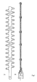
- Fig. 1 - Schematic layout of mechanical device, in which a, b and c indicate some of the blade positions;
- Fig. 2 - Schematic layout of mechanical device, showing that blades may be set in any position: a, b, c, d, etc;
- Fig. 3A - Schematic diagram of a blade;
- Fig. 3B - Blade unit on adjustable support;
- Fig. 4 - Cross-section of device;
- Fig.5 - Gear box;
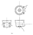
- Fig. 6- Main body showing fixing points and adjustment device;
- Fig. 7 - Gear box with clutch unit;
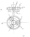
- Fig. 8 - Epicycloidal gear unit with straight teeth;
- Fig. 9 - Lower and upper oscillating rods;
- Fig. 10 - Circular rack ratchet lock;
- Fig. 4 shows a cross-section of the device, indicating:
- 1. - main body with co-printed bearing;
- 2. - gear box;
- 3. - oscillating blade rotation lock ring;
- 4. - blade and bar housing rotational support;
- 5. - bell or flange-shaped bracket for fixing bevel gear pair;
- 6. - limited slip clutch unit pre-loading ring, central unit and clutch rings;
- 7. - disk spring for pre-loading clutch unit;
- 8. - seger/ lock ring;
- 9. - epicicloidal reduction gears;
- 10. - reduction gear collar;
- 11. - gear wheel support unit with transmission shaft secondary shaft coupling;
- 12. - opposing rockers;
- 13. - secondary transmission axis;
- 14. - primary transmission axis with gearing;
- 15. - bearing;
- 16. - gearing connected to transmission axis;
- 17.- spacer;
- 18. - co-printed bearing on gear box;
- 19. - oscillating unit with rotational joint upper and lower rods;
- 20. - oscillating unit with rotational joint lower rod;
- 21. - mobile unit with coupling to cutting bar and upper rod;
- 22. - mobile unit with coupling to cutting bar and lower rod;
- 23. - cutting bar fixing screws;
- 24. - cutting bars;
- 25. - upper rod;
- 26. - lower rod;
- 27. - adaptation washer to bevel gear pair;
- 28. - standard bevel gear pair for a trimming machine;
- 29. - support and alignment ring for oscillating unit gear box;
- 30. - bell/flange bracket fixing screws;
- 31. - ribbed joint for coupling mechanism and bevel gear pair;
- 32. - oscillating unit housing;
- 33. - printed insert on oscillating unit box;
- 34. - oscillating blades support rod;
- 35. - large-headed nuts to fix blades;
- Fig. 5 shows the gear box, with:
- 5a - view from above in which 5.1 indicates the inserts;
- 5b - cross-section in which 5.1 indicates inserts;
- 5c - side view in which 18 indicates the co-printed bearing;
- Fig. 6 shows the main body, with:
- 6a - cross-section in which 15 is a bearing and 30 the lock screws;
- 6b - view from above;
- Fig. 7 shows the
gear box 2, in which: - 6. - lock ring;
- 7. - disk spring for pre-loading clutch unit
- 8. - seger ring;
- 10.- crown wheel;
- Fig. 8 shows the reduction unit, in which:
- 8a is the cross-section in which:
- 9. - three gear wheels;
- 10. - reduction ring;
- 11. - gear wheel housing unit;
- 14. - primary transmission axis with gears, in which:
- 8b is the view from above and 9 the gear wheels;
- Fig. 9 shows:
- 21. - mobile device;
- 25. - upper oscillating rod;
- 26. - lower oscillating rod;
- Fig. 10 shows:
- 29. - support and alignment ring for oscillating unit gear box;
- 36. -
Rack ratchet lock 29, fitted withspring 37. -
- The mechanism is powered by any type of trimming machine. By means of a
primary transmission axis reduction unit Collar 10 is held on two rings 6 pre-loaded byspring 7 held byseger 8. This all enables a controlled sliding ofcollar 10. This is necessary so that when the blade of the mechanism encounters a hard obstacle (e.g. metal wire) the unit starts to slide so that thecollar 10 runs on the runners 6, thereby avoiding any damage to the mechanism, which would have blocked blades on one side and an operational motor on the other. The operator avoids the obstacle and returns to work. - The
secondary shaft 13, which takes its movement fromreduction unit 11, transmits the movement to two rockingcams 12. - The rocking
cams 12 are held in tworods rods blades 24 are fixed on the rotating joint 21, 20 by means of thescrews 23. Since the blades are easily fixed they may be easily removed for maintenance purposes. In fact, the blade unit, as shown in Fig. 3, slides from the rotational unit which provides the transmission movement. All the parts with alternative movement are out of phase by 180° and balanced with each other in order to minimise the vibrations. - The movement on the horizontal plane, in order to adjust the mechanism at approximately 90° intervals is carried out by unlocking a ratchet fixed on
collar 29 and releasing it in the desired position, usually by means of a pushbutton command. - The ratchet is composed of a lever on one side of which are the ratchets for locking
support ring 29 and on the other side of which is a knob to unlock the clamp. The position is fixed by means of aspring 37 which holds the ratchet.
Claims (2)
- Mechanical device characterized by: a main body (1) with co-printed bearing, a gear box (2), an oscillating blades rotation lock ring (3), a rotational support of the blades and bars support (4), a bell or flange bracket to fix the bevel gear pair (5), a limited slip clutch unit pre-load ring, centring and friction rings (6), disk spring to pre-load clutch unit (7), lock ring/seger (8), epicycloidal reduction box gears (9), reduction collar (10), gear wheels support unit with transmission shaft secondary shaft coupling (11), opposing rockers (12), secondary transmission axis (13), primary transmission axis with gearing (14), a bearing (15), gearing connected to transmission axis (16), a spacer (17), a co-printed bearing on gear box (18), oscillating unit with rotational joint upper and lower rods (19), oscillating unit with rotational joint lower rod (20), mobile unit with coupling to cutting bar and upper rod (21), mobile unit with coupling to cutting bar and lower rod(22), cutting bar fixing screws (23), cutting bars (24), upper rod (25), lower rod (26), adaptation washer to bevel gear pair (27), standard bevel gear pair for a trimming machine (28), support and alignment ring for oscillating unit gear box (29), bell/flange bracket fixing screws (30), ribbed joint for coupling mechanism and bevel gear pair (31), oscillating unit housing (32), insert on oscillating unit box (33), oscillating blades support rod (34), large-headed nuts to fix blades (35).
- Mechanical device, according to claim 1, characterized by the ability to operate on all orthogonal planes said device being constituted by its connection to toothed blades with alternative movements , adjusted to any angle, by means of a gear box (2) which provides the alternative movement; said gear box (2) being connected o the main body where, by means of a collar (29) and a ratchet (36, 37), the adjustments may be made in the plane passing through the transmission axis (31, 16, 14) of the bevel gear pair (28) forming part of the trimming machine.
Applications Claiming Priority (2)
| Application Number | Priority Date | Filing Date | Title |
|---|---|---|---|
| ITRM20020028 | 2002-01-23 | ||
| IT2002RM000028A ITRM20020028A1 (en) | 2002-01-23 | 2002-01-23 | MECHANICAL DEVICE WITH OSCILLATING BLADES THAT CAN BE MOVED ON ALL ORTHOGONAL PLANES. |
Publications (2)
| Publication Number | Publication Date |
|---|---|
| EP1332665A1 true EP1332665A1 (en) | 2003-08-06 |
| EP1332665B1 EP1332665B1 (en) | 2007-12-12 |
Family
ID=11455976
Family Applications (1)
| Application Number | Title | Priority Date | Filing Date |
|---|---|---|---|
| EP03425019A Expired - Lifetime EP1332665B1 (en) | 2002-01-23 | 2003-01-16 | Mechanical device with oscillating blades which may be moved on all the orthogonal planes |
Country Status (6)
| Country | Link |
|---|---|
| US (1) | US20030136003A1 (en) |
| EP (1) | EP1332665B1 (en) |
| AT (1) | ATE380460T1 (en) |
| CA (1) | CA2415633A1 (en) |
| DE (1) | DE60317954D1 (en) |
| IT (1) | ITRM20020028A1 (en) |
Cited By (2)
| Publication number | Priority date | Publication date | Assignee | Title |
|---|---|---|---|---|
| DE102005048766A1 (en) * | 2005-10-10 | 2007-05-16 | Guenter Schumacher | Drive unit for a mower blade |
| EP2814313A4 (en) * | 2012-02-17 | 2015-09-30 | Husqvarna Ab | Hand-held motor-driven cutting device |
Families Citing this family (9)
| Publication number | Priority date | Publication date | Assignee | Title |
|---|---|---|---|---|
| US20050172498A1 (en) * | 2002-01-23 | 2005-08-11 | Franco Castelmani | Mechanical device with powered tool orientable along three orthogonal planes, particularly a device for agricultural and garden tools |
| US7752760B2 (en) * | 2005-06-30 | 2010-07-13 | Black & Decker, Inc. | Portable trimmer having rotatable power head |
| US9764486B2 (en) * | 2013-04-04 | 2017-09-19 | Milwaukee Electric Tool Corporation | Power tool |
| JP6492656B2 (en) * | 2014-12-26 | 2019-04-03 | 工機ホールディングス株式会社 | Reciprocating tool |
| US10375896B2 (en) | 2016-04-21 | 2019-08-13 | Black & Decker, Inc. | Pole hedge trimmer |
| US11284568B2 (en) | 2018-05-23 | 2022-03-29 | Milwaukee Electric Tool Corporation | Hedge trimmer |
| JP2019088333A (en) * | 2019-03-07 | 2019-06-13 | 工機ホールディングス株式会社 | Reciprocation tool |
| JP7249228B2 (en) * | 2019-07-18 | 2023-03-30 | 株式会社マキタ | electric work machine |
| US12011840B2 (en) | 2021-09-22 | 2024-06-18 | Harbor Freight Tools Usa, Inc. | Rotatable tool head |
Citations (5)
| Publication number | Priority date | Publication date | Assignee | Title |
|---|---|---|---|---|
| US3802222A (en) * | 1972-08-30 | 1974-04-09 | Black & Decker Mfg Co | Torque-responsive clutch for hedge trimmers and the like |
| FR2575363A1 (en) * | 1984-12-27 | 1986-07-04 | Robert Jacques | Portable hay cutter for high-density and medium-density bales |
| US5054202A (en) * | 1989-02-07 | 1991-10-08 | Ars Edge Co., Ltd. | Pruning machine |
| USH1428H (en) * | 1992-08-14 | 1995-04-04 | Kioritz Corp. | Reciprocating cutter type trimmer |
| EP0687409A1 (en) * | 1994-06-18 | 1995-12-20 | Black & Decker Inc. | Improved cutting device |
Family Cites Families (13)
| Publication number | Priority date | Publication date | Assignee | Title |
|---|---|---|---|---|
| US2468312A (en) * | 1948-01-10 | 1949-04-26 | Turner Peter | Push-type offset mower |
| US4100677A (en) * | 1977-02-15 | 1978-07-18 | Jeff Adolph L | Precision cutting tool |
| USRE32266E (en) * | 1979-06-25 | 1986-10-21 | Emerson Electric Co. | Lawn edger |
| US4757613A (en) * | 1987-05-04 | 1988-07-19 | Baudreau Archie E | Chain saw extension structure |
| US4991298A (en) * | 1988-09-13 | 1991-02-12 | David K. Caruso | Extendible tree trimming apparatus |
| JP2537481Y2 (en) * | 1990-06-06 | 1997-06-04 | 株式会社共立 | Hair clipper type brush cutter |
| JP3338543B2 (en) * | 1994-01-20 | 2002-10-28 | 株式会社マキタ | Hedge trimmer |
| USRE37211E1 (en) * | 1994-12-13 | 2001-06-12 | Milwaukee Electric Tool Corporation | Clutch mechanism for reciprocating saws |
| US5718050A (en) * | 1996-03-08 | 1998-02-17 | Technic Tool Corporation | Pruning cutter |
| US6170159B1 (en) * | 1996-10-29 | 2001-01-09 | Andreas Stihl Ag & Co. | Manually guided implement having a drive motor |
| JPH10327669A (en) * | 1997-05-27 | 1998-12-15 | Kioritz Corp | Hair clipper cutting blade |
| DE19808118C2 (en) * | 1998-02-26 | 2000-04-20 | Stihl Maschf Andreas | Hedge trimmer |
| DE10003984A1 (en) * | 2000-01-29 | 2001-08-02 | Stihl Maschf Andreas | Tool with a drive motor |
-
2002
- 2002-01-23 IT IT2002RM000028A patent/ITRM20020028A1/en unknown
-
2003
- 2003-01-06 CA CA002415633A patent/CA2415633A1/en not_active Abandoned
- 2003-01-07 US US10/337,472 patent/US20030136003A1/en not_active Abandoned
- 2003-01-16 EP EP03425019A patent/EP1332665B1/en not_active Expired - Lifetime
- 2003-01-16 AT AT03425019T patent/ATE380460T1/en not_active IP Right Cessation
- 2003-01-16 DE DE60317954T patent/DE60317954D1/en not_active Expired - Lifetime
Patent Citations (5)
| Publication number | Priority date | Publication date | Assignee | Title |
|---|---|---|---|---|
| US3802222A (en) * | 1972-08-30 | 1974-04-09 | Black & Decker Mfg Co | Torque-responsive clutch for hedge trimmers and the like |
| FR2575363A1 (en) * | 1984-12-27 | 1986-07-04 | Robert Jacques | Portable hay cutter for high-density and medium-density bales |
| US5054202A (en) * | 1989-02-07 | 1991-10-08 | Ars Edge Co., Ltd. | Pruning machine |
| USH1428H (en) * | 1992-08-14 | 1995-04-04 | Kioritz Corp. | Reciprocating cutter type trimmer |
| EP0687409A1 (en) * | 1994-06-18 | 1995-12-20 | Black & Decker Inc. | Improved cutting device |
Cited By (3)
| Publication number | Priority date | Publication date | Assignee | Title |
|---|---|---|---|---|
| DE102005048766A1 (en) * | 2005-10-10 | 2007-05-16 | Guenter Schumacher | Drive unit for a mower blade |
| US7708664B2 (en) | 2005-10-10 | 2010-05-04 | Gunter Schumacher | Drive unit for a mowing sickle |
| EP2814313A4 (en) * | 2012-02-17 | 2015-09-30 | Husqvarna Ab | Hand-held motor-driven cutting device |
Also Published As
| Publication number | Publication date |
|---|---|
| ITRM20020028A0 (en) | 2002-01-23 |
| CA2415633A1 (en) | 2003-07-23 |
| DE60317954D1 (en) | 2008-01-24 |
| US20030136003A1 (en) | 2003-07-24 |
| EP1332665B1 (en) | 2007-12-12 |
| ITRM20020028A1 (en) | 2003-07-23 |
| ATE380460T1 (en) | 2007-12-15 |
Similar Documents
| Publication | Publication Date | Title |
|---|---|---|
| US4881363A (en) | Mowing machine | |
| EP1332665B1 (en) | Mechanical device with oscillating blades which may be moved on all the orthogonal planes | |
| RU2502254C2 (en) | Mechanised portable electric tool with two handles | |
| US6779325B1 (en) | Edging and trimming assembly for lawn mower | |
| US4651420A (en) | Universal vegetation cutter or UVC | |
| JP4754827B2 (en) | A tool driven by a rotating machine such as a Sasa type hedge trimming machine with a lock mechanism for a rotatable cutting device. | |
| US3204704A (en) | Powered garden tiller and attachments therefor | |
| US9078387B2 (en) | Hand-held powered soil cultivation device | |
| CN100358691C (en) | Safety apparatus for free pruning machine | |
| CN109089522B (en) | Weeder with ceramic blade | |
| KR102737856B1 (en) | Trimmer for excavator with rotating device | |
| US2702978A (en) | Lawn mower and edger | |
| JPH07194223A (en) | Mechanical rake | |
| CN106258027A (en) | Portable mowing stump extractor | |
| GB2026928A (en) | Flail-type cutter with adjustable handle and handgrip | |
| US1579783A (en) | Trimming device | |
| KR102612107B1 (en) | Weeding machine with rotation axis parallel to direction of travel | |
| KR102547624B1 (en) | Lawn trimmer | |
| US20050076628A1 (en) | Ground supported motorized sickle bar mower for use on sloping terrain | |
| US20150342115A1 (en) | Lawn maintenance device | |
| US3218789A (en) | Lawn edge and hedge trimmer | |
| US1445515A (en) | Grass trimmer | |
| KR101011902B1 (en) | Supporting devices for mowers | |
| EP1106044A1 (en) | Portable handeled tool for use in farming and gardening works provided with an improved handle | |
| US20050172498A1 (en) | Mechanical device with powered tool orientable along three orthogonal planes, particularly a device for agricultural and garden tools |
Legal Events
| Date | Code | Title | Description |
|---|---|---|---|
| PUAI | Public reference made under article 153(3) epc to a published international application that has entered the european phase |
Free format text: ORIGINAL CODE: 0009012 |
|
| AK | Designated contracting states |
Designated state(s): AT BE BG CH CY CZ DE DK EE ES FI FR GB GR HU IE IT LI LU MC NL PT SE SI SK TR |
|
| AX | Request for extension of the european patent |
Extension state: AL LT LV MK RO |
|
| 17P | Request for examination filed |
Effective date: 20031218 |
|
| AKX | Designation fees paid |
Designated state(s): AT BE BG CH CY CZ DE DK EE ES FI FR GB GR HU IE IT LI LU MC NL PT SE SI SK TR |
|
| GRAP | Despatch of communication of intention to grant a patent |
Free format text: ORIGINAL CODE: EPIDOSNIGR1 |
|
| GRAS | Grant fee paid |
Free format text: ORIGINAL CODE: EPIDOSNIGR3 |
|
| GRAA | (expected) grant |
Free format text: ORIGINAL CODE: 0009210 |
|
| AK | Designated contracting states |
Kind code of ref document: B1 Designated state(s): AT BE BG CH CY CZ DE DK EE ES FI FR GB GR HU IE IT LI LU MC NL PT SE SI SK TR |
|
| REG | Reference to a national code |
Ref country code: GB Ref legal event code: FG4D |
|
| REG | Reference to a national code |
Ref country code: CH Ref legal event code: EP |
|
| REG | Reference to a national code |
Ref country code: IE Ref legal event code: FG4D |
|
| REF | Corresponds to: |
Ref document number: 60317954 Country of ref document: DE Date of ref document: 20080124 Kind code of ref document: P |
|
| REG | Reference to a national code |
Ref country code: CH Ref legal event code: NV Representative=s name: E. BLUM & CO. AG PATENT- UND MARKENANWAELTE VSP |
|
| PG25 | Lapsed in a contracting state [announced via postgrant information from national office to epo] |
Ref country code: SE Free format text: LAPSE BECAUSE OF FAILURE TO SUBMIT A TRANSLATION OF THE DESCRIPTION OR TO PAY THE FEE WITHIN THE PRESCRIBED TIME-LIMIT Effective date: 20080312 |
|
| PG25 | Lapsed in a contracting state [announced via postgrant information from national office to epo] |
Ref country code: SI Free format text: LAPSE BECAUSE OF FAILURE TO SUBMIT A TRANSLATION OF THE DESCRIPTION OR TO PAY THE FEE WITHIN THE PRESCRIBED TIME-LIMIT Effective date: 20071212 Ref country code: FI Free format text: LAPSE BECAUSE OF FAILURE TO SUBMIT A TRANSLATION OF THE DESCRIPTION OR TO PAY THE FEE WITHIN THE PRESCRIBED TIME-LIMIT Effective date: 20071212 Ref country code: NL Free format text: LAPSE BECAUSE OF FAILURE TO SUBMIT A TRANSLATION OF THE DESCRIPTION OR TO PAY THE FEE WITHIN THE PRESCRIBED TIME-LIMIT Effective date: 20071212 |
|
| NLV1 | Nl: lapsed or annulled due to failure to fulfill the requirements of art. 29p and 29m of the patents act | ||
| PG25 | Lapsed in a contracting state [announced via postgrant information from national office to epo] |
Ref country code: AT Free format text: LAPSE BECAUSE OF FAILURE TO SUBMIT A TRANSLATION OF THE DESCRIPTION OR TO PAY THE FEE WITHIN THE PRESCRIBED TIME-LIMIT Effective date: 20071212 |
|
| PG25 | Lapsed in a contracting state [announced via postgrant information from national office to epo] |
Ref country code: DE Free format text: LAPSE BECAUSE OF FAILURE TO SUBMIT A TRANSLATION OF THE DESCRIPTION OR TO PAY THE FEE WITHIN THE PRESCRIBED TIME-LIMIT Effective date: 20080313 Ref country code: CZ Free format text: LAPSE BECAUSE OF FAILURE TO SUBMIT A TRANSLATION OF THE DESCRIPTION OR TO PAY THE FEE WITHIN THE PRESCRIBED TIME-LIMIT Effective date: 20071212 Ref country code: ES Free format text: LAPSE BECAUSE OF FAILURE TO SUBMIT A TRANSLATION OF THE DESCRIPTION OR TO PAY THE FEE WITHIN THE PRESCRIBED TIME-LIMIT Effective date: 20080323 |
|
| ET | Fr: translation filed | ||
| PG25 | Lapsed in a contracting state [announced via postgrant information from national office to epo] |
Ref country code: MC Free format text: LAPSE BECAUSE OF NON-PAYMENT OF DUE FEES Effective date: 20080131 Ref country code: SK Free format text: LAPSE BECAUSE OF FAILURE TO SUBMIT A TRANSLATION OF THE DESCRIPTION OR TO PAY THE FEE WITHIN THE PRESCRIBED TIME-LIMIT Effective date: 20071212 Ref country code: BE Free format text: LAPSE BECAUSE OF FAILURE TO SUBMIT A TRANSLATION OF THE DESCRIPTION OR TO PAY THE FEE WITHIN THE PRESCRIBED TIME-LIMIT Effective date: 20071212 |
|
| PG25 | Lapsed in a contracting state [announced via postgrant information from national office to epo] |
Ref country code: PT Free format text: LAPSE BECAUSE OF FAILURE TO SUBMIT A TRANSLATION OF THE DESCRIPTION OR TO PAY THE FEE WITHIN THE PRESCRIBED TIME-LIMIT Effective date: 20080512 |
|
| PLBE | No opposition filed within time limit |
Free format text: ORIGINAL CODE: 0009261 |
|
| STAA | Information on the status of an ep patent application or granted ep patent |
Free format text: STATUS: NO OPPOSITION FILED WITHIN TIME LIMIT |
|
| PG25 | Lapsed in a contracting state [announced via postgrant information from national office to epo] |
Ref country code: DK Free format text: LAPSE BECAUSE OF FAILURE TO SUBMIT A TRANSLATION OF THE DESCRIPTION OR TO PAY THE FEE WITHIN THE PRESCRIBED TIME-LIMIT Effective date: 20071212 |
|
| 26N | No opposition filed |
Effective date: 20080915 |
|
| PG25 | Lapsed in a contracting state [announced via postgrant information from national office to epo] |
Ref country code: IE Free format text: LAPSE BECAUSE OF NON-PAYMENT OF DUE FEES Effective date: 20080116 Ref country code: GR Free format text: LAPSE BECAUSE OF FAILURE TO SUBMIT A TRANSLATION OF THE DESCRIPTION OR TO PAY THE FEE WITHIN THE PRESCRIBED TIME-LIMIT Effective date: 20080313 Ref country code: EE Free format text: LAPSE BECAUSE OF FAILURE TO SUBMIT A TRANSLATION OF THE DESCRIPTION OR TO PAY THE FEE WITHIN THE PRESCRIBED TIME-LIMIT Effective date: 20071212 |
|
| PG25 | Lapsed in a contracting state [announced via postgrant information from national office to epo] |
Ref country code: BG Free format text: LAPSE BECAUSE OF FAILURE TO SUBMIT A TRANSLATION OF THE DESCRIPTION OR TO PAY THE FEE WITHIN THE PRESCRIBED TIME-LIMIT Effective date: 20080312 |
|
| PGFP | Annual fee paid to national office [announced via postgrant information from national office to epo] |
Ref country code: CH Payment date: 20090114 Year of fee payment: 7 Ref country code: GB Payment date: 20090114 Year of fee payment: 7 |
|
| PG25 | Lapsed in a contracting state [announced via postgrant information from national office to epo] |
Ref country code: CY Free format text: LAPSE BECAUSE OF FAILURE TO SUBMIT A TRANSLATION OF THE DESCRIPTION OR TO PAY THE FEE WITHIN THE PRESCRIBED TIME-LIMIT Effective date: 20071212 |
|
| PGFP | Annual fee paid to national office [announced via postgrant information from national office to epo] |
Ref country code: FR Payment date: 20090113 Year of fee payment: 7 |
|
| PG25 | Lapsed in a contracting state [announced via postgrant information from national office to epo] |
Ref country code: LU Free format text: LAPSE BECAUSE OF NON-PAYMENT OF DUE FEES Effective date: 20080116 Ref country code: HU Free format text: LAPSE BECAUSE OF FAILURE TO SUBMIT A TRANSLATION OF THE DESCRIPTION OR TO PAY THE FEE WITHIN THE PRESCRIBED TIME-LIMIT Effective date: 20080613 |
|
| PG25 | Lapsed in a contracting state [announced via postgrant information from national office to epo] |
Ref country code: TR Free format text: LAPSE BECAUSE OF FAILURE TO SUBMIT A TRANSLATION OF THE DESCRIPTION OR TO PAY THE FEE WITHIN THE PRESCRIBED TIME-LIMIT Effective date: 20071212 |
|
| REG | Reference to a national code |
Ref country code: CH Ref legal event code: PL |
|
| GBPC | Gb: european patent ceased through non-payment of renewal fee |
Effective date: 20100116 |
|
| REG | Reference to a national code |
Ref country code: FR Ref legal event code: ST Effective date: 20100930 |
|
| PG25 | Lapsed in a contracting state [announced via postgrant information from national office to epo] |
Ref country code: FR Free format text: LAPSE BECAUSE OF NON-PAYMENT OF DUE FEES Effective date: 20100201 Ref country code: CH Free format text: LAPSE BECAUSE OF NON-PAYMENT OF DUE FEES Effective date: 20100131 Ref country code: LI Free format text: LAPSE BECAUSE OF NON-PAYMENT OF DUE FEES Effective date: 20100131 |
|
| PG25 | Lapsed in a contracting state [announced via postgrant information from national office to epo] |
Ref country code: GB Free format text: LAPSE BECAUSE OF NON-PAYMENT OF DUE FEES Effective date: 20100116 |
|
| PG25 | Lapsed in a contracting state [announced via postgrant information from national office to epo] |
Ref country code: IT Free format text: LAPSE BECAUSE OF NON-PAYMENT OF DUE FEES Effective date: 20090116 |
|
| PGFP | Annual fee paid to national office [announced via postgrant information from national office to epo] |
Ref country code: IT Payment date: 20090202 Year of fee payment: 7 |
|
| PGRI | Patent reinstated in contracting state [announced from national office to epo] |
Ref country code: IT Effective date: 20110616 |
|
| PGRI | Patent reinstated in contracting state [announced from national office to epo] |
Ref country code: IT Effective date: 20110616 |